CN218800808U - Material and scrap separator for numerical control instrument vehicle - Google Patents
Material and scrap separator for numerical control instrument vehicle Download PDFInfo
- Publication number
- CN218800808U CN218800808U CN202222258172.1U CN202222258172U CN218800808U CN 218800808 U CN218800808 U CN 218800808U CN 202222258172 U CN202222258172 U CN 202222258172U CN 218800808 U CN218800808 U CN 218800808U
- Authority
- CN
- China
- Prior art keywords
- motor
- fixedly installed
- rotating shaft
- reducer
- numerical control
- Prior art date
- Legal status (The legal status is an assumption and is not a legal conclusion. Google has not performed a legal analysis and makes no representation as to the accuracy of the status listed.)
- Expired - Fee Related
Links
Images


Classifications
-
- Y—GENERAL TAGGING OF NEW TECHNOLOGICAL DEVELOPMENTS; GENERAL TAGGING OF CROSS-SECTIONAL TECHNOLOGIES SPANNING OVER SEVERAL SECTIONS OF THE IPC; TECHNICAL SUBJECTS COVERED BY FORMER USPC CROSS-REFERENCE ART COLLECTIONS [XRACs] AND DIGESTS
- Y02—TECHNOLOGIES OR APPLICATIONS FOR MITIGATION OR ADAPTATION AGAINST CLIMATE CHANGE
- Y02P—CLIMATE CHANGE MITIGATION TECHNOLOGIES IN THE PRODUCTION OR PROCESSING OF GOODS
- Y02P70/00—Climate change mitigation technologies in the production process for final industrial or consumer products
- Y02P70/10—Greenhouse gas [GHG] capture, material saving, heat recovery or other energy efficient measures, e.g. motor control, characterised by manufacturing processes, e.g. for rolling metal or metal working
Landscapes
- Electrical Discharge Machining, Electrochemical Machining, And Combined Machining (AREA)
Abstract
本实用新型公开了一种数控仪表车用料屑分离器,包括数控仪表车床本体,数控仪表车床本体的底端安装有工作台,工作台的底端安装有安装板,安装板的顶端固定安装有收料箱,收料箱的内部两侧均开设有侧槽;数控仪表车床本体加工出来的工件以及料屑掉落到收料箱内,通过滤板可以对工件以及料屑进行过滤,通过第一电机带动第一减速机进行转动,第一减速机带动第一转轴进行转动,第一转轴带动转杆进行转动,转杆的转动使得凸轮进行转动,凸轮的转动可以间接性的将滤板顶起,然后滤板可以做落体运动,通过弹簧的作用,使得滤板可以再一定程度上进行抖动,进而可以增强过滤效果,避免大量的料屑堆积在滤板上,影响滤板的通过性。

The utility model discloses a material chip separator for a numerically controlled instrument vehicle, which comprises a numerically controlled instrument lathe body, a worktable is installed at the bottom of the numerically controlled instrument lathe body, a mounting plate is installed at the bottom of the workbench, and the top of the mounting plate is fixedly installed. There is a receiving box, and there are side grooves on both sides of the receiving box; the workpieces and scraps processed by the CNC instrument lathe body fall into the receiving box, and the workpieces and scraps can be filtered through the filter plate. The first motor drives the first reducer to rotate, the first reducer drives the first rotating shaft to rotate, the first rotating shaft drives the rotating rod to rotate, the rotation of the rotating rod makes the cam rotate, and the rotation of the cam can indirectly rotate the filter plate Jack up, and then the filter plate can do a falling motion. Through the action of the spring, the filter plate can shake to a certain extent, which can enhance the filtering effect and avoid a large amount of material debris accumulating on the filter plate, which affects the passability of the filter plate. .
Description
技术领域technical field
本实用新型属于数控仪表车床技术领域,具体来说,涉及一种数控仪表车用料屑分离器。The utility model belongs to the technical field of numerically controlled instrument lathes, in particular to a scrap separator for numerically controlled instrument lathes.
背景技术Background technique
数控仪表车床实际上是数控车床的一个分支种类,因其价格便宜,精度尚可,被广泛应用于小型零件加工领域。现有数控仪表车的工件与切削物一同排出,需要进行人工分拣,工作人员的劳动强度大,效率低下,且在此过程中还需要停机操作,限制了数控仪表车床的使用效果以及其加工效率。The CNC instrument lathe is actually a branch of the CNC lathe. Because of its cheap price and acceptable accuracy, it is widely used in the field of small parts processing. The workpieces of the existing CNC instrument lathe are discharged together with the cuttings, requiring manual sorting. The labor intensity of the staff is high, the efficiency is low, and the shutdown operation is required during the process, which limits the use effect of the CNC instrument lathe and its processing. efficiency.
针对相关技术中的问题,目前尚未提出有效的解决方案。Aiming at the problems in the related technologies, no effective solution has been proposed yet.
因此为了解决以上问题,本实用新型提供了一种数控仪表车用料屑分离器。Therefore, in order to solve the above problems, the utility model provides a chip separator for a numerically controlled instrument vehicle.
实用新型内容Utility model content
本实用新型的目的在于提供一种数控仪表车用料屑分离器,以解决上述背景技术中提出的问题。The purpose of this utility model is to provide a material chip separator for a numerically controlled instrument vehicle to solve the problems raised in the above-mentioned background technology.
为实现上述目的,本实用新型提供如下技术方案:一种数控仪表车用料屑分离器,包括数控仪表车床本体,所述数控仪表车床本体的底端安装有工作台,所述工作台的底端安装有安装板,所述安装板的顶端固定安装有收料箱,所述收料箱的内部两侧均开设有侧槽,所述侧槽的内部底端固定安装有弹簧,所述弹簧的顶端连接有连接块,两组所述连接块之间安装有滤板,所述收料箱的一侧固定安装有电机箱,所述电机箱的内部安装有第一电机,所述第一电机的一侧固定安装有第一减速机,所述第一减速机的一侧安装有第一转轴,所述第一转轴的一端固定安装有转杆,所述转杆上固定安装有凸轮,所述安装板的顶端一侧还固定安装有侧柱,所述侧柱的一侧开设有滑槽,所述滑槽的内部安装有第二电机,所述第二电机的底端固定安装有第二减速机,所述第二减速机的底端安装有第二转轴,所述第二转轴的底端固定安装有螺纹杆,所述螺纹杆上螺纹连接有滑块,所述滑块的一侧固定安装有电动伸缩杆,所述电动伸缩杆的一端固定安装有清理板。In order to achieve the above purpose, the utility model provides the following technical solutions: a chip separator for CNC instrument car, including a CNC instrument lathe body, a workbench is installed at the bottom of the CNC instrument lathe body, and the bottom of the workbench A mounting plate is installed at the top of the mounting plate, and a receiving box is fixedly installed on the top of the mounting plate. Side grooves are opened on both sides of the inside of the receiving box, and springs are fixedly installed at the inner bottom of the side grooves. The springs A connecting block is connected to the top of the connecting block, a filter plate is installed between the two groups of connecting blocks, a motor box is fixedly installed on one side of the receiving box, a first motor is installed inside the motor box, and the first One side of the motor is fixedly installed with a first reducer, one side of the first reducer is installed with a first rotating shaft, one end of the first rotating shaft is fixedly installed with a rotating rod, and a cam is fixedly installed on the rotating rod, A side column is fixedly installed on one side of the top of the mounting plate, a chute is provided on one side of the side column, a second motor is installed inside the chute, and a bottom end of the second motor is fixedly installed with a The second speed reducer, the bottom end of the second speed reducer is equipped with a second rotating shaft, the bottom end of the second rotating shaft is fixedly installed with a threaded rod, and a slider is threaded on the threaded rod, and the slider is An electric telescopic rod is fixedly installed on one side, and a cleaning plate is fixedly installed on one end of the electric telescopic rod.
进一步的,所述工作台上开设有出料孔,所述工作台的底端两侧均固定安装有支撑板,两组所述支撑板之间固定安装有所述安装板。Further, a discharge hole is provided on the workbench, support plates are fixedly installed on both sides of the bottom end of the workbench, and the installation plate is fixedly installed between the two sets of support plates.
进一步的,所述连接块滑动连接于所述侧槽的内部,所述收料箱的一侧开设有第一排料口和第二排料口,所述收料箱的另一侧开设有第一清理口和第二清理口,所述第一清理口内安装有第一阀门,所述第二清理口内安装有第二阀门,所述第一排料口和所述第一清理口的位置相对应,所述第二排料口和所述第二清理口的位置相对应。Further, the connecting block is slidably connected to the inside of the side groove, a first discharge opening and a second discharge opening are opened on one side of the receiving box, and a discharge opening is opened on the other side of the receiving box The first cleaning port and the second cleaning port, the first valve is installed in the first cleaning port, the second valve is installed in the second cleaning port, the position of the first discharge port and the first cleaning port Correspondingly, the positions of the second discharge port and the second cleaning port are corresponding.
进一步的,所述电机箱的内部一侧固定安装有第一固定座,所述第一固定座的一侧固定安装有所述第一电机,所述第一电机内转轴的输出端通过联轴器与所述第一减速机内转轴的接收端相连接,所述第一减速机内转轴的输出端通过联轴器与所述第一转轴的一端相连接。Further, a first fixed base is fixedly installed on one side of the motor box, and the first motor is fixedly installed on one side of the first fixed base, and the output end of the inner rotating shaft of the first motor is passed through a shaft coupling. The device is connected to the receiving end of the inner shaft of the first reducer, and the output end of the inner shaft of the first reducer is connected to one end of the first shaft through a coupling.
进一步的,所述滑槽的内部顶端固定安装有第二固定座,所述第二固定座的底端固定安装有所述第二电机,所述第二电机内转轴的输出端通过联轴器与所述第二减速机内转轴的接收端相连接,所述第二减速机内转轴的输出端通过联轴器与所述第二转轴的顶端相连接。Further, the inner top end of the chute is fixedly installed with a second fixed seat, the bottom end of the second fixed seat is fixedly installed with the second motor, and the output end of the inner shaft of the second motor passes through a coupling It is connected with the receiving end of the inner rotating shaft of the second reducer, and the output end of the inner rotating shaft of the second reducer is connected with the top end of the second rotating shaft through a coupling.
进一步的,所述滑槽的内部底端固定安装有第三固定座,所述螺纹杆的底端与所述第三固定座转动连接,所述滑块滑动连接于所述滑槽的内部。Further, a third fixing seat is fixedly installed at the inner bottom end of the chute, the bottom end of the threaded rod is rotatably connected to the third fixing seat, and the slider is slidably connected to the inside of the chute.
与现有技术相比,本实用新型具有以下有益效果:Compared with the prior art, the utility model has the following beneficial effects:
1.本实用新型中,数控仪表车床本体加工出来的工件以及料屑掉落到收料箱内,通过滤板可以对工件以及料屑进行过滤,通过第一电机带动第一减速机进行转动,第一减速机带动第一转轴进行转动,第一转轴带动转杆进行转动,转杆的转动使得凸轮进行转动,凸轮的转动可以间接性的将滤板顶起,然后滤板可以做落体运动,通过弹簧的作用,使得滤板可以再一定程度上进行抖动,进而可以增强过滤效果,避免大量的料屑堆积在滤板上,影响滤板的通过性。1. In this utility model, the workpieces and scraps processed by the CNC instrument lathe body fall into the receiving box, and the workpieces and scraps can be filtered through the filter plate, and the first reducer is driven by the first motor to rotate. The first reducer drives the first rotating shaft to rotate, the first rotating shaft drives the rotating rod to rotate, the rotation of the rotating rod causes the cam to rotate, the rotation of the cam can indirectly lift the filter plate, and then the filter plate can do a falling motion, Through the action of the spring, the filter plate can be shaken to a certain extent, thereby enhancing the filtering effect and avoiding a large amount of material debris accumulating on the filter plate, which affects the passability of the filter plate.
2.本实用新型中,通过电动伸缩杆的作用使得清理板可以伸入到收料箱的内部,进而可以对滤板上的工件进行清理以及对收料箱内底部的料屑进行清理,通过第二电机带动第二减速机进行转动,第二减速机带动第二转轴进行转动,第二转轴带动螺纹杆进行转动,螺纹杆的转动使得滑块可以在滑槽内进行滑动,从而使得清理板的高度可以被调整,使得其可以依次的对滤板上的工件以及对收料箱内底部的料屑进行清理。2. In the utility model, the cleaning plate can be extended into the inside of the receiving box through the action of the electric telescopic rod, and then the workpiece on the filter plate can be cleaned and the scraps at the bottom of the receiving box can be cleaned. The second motor drives the second reducer to rotate, the second reducer drives the second rotating shaft to rotate, the second rotating shaft drives the threaded rod to rotate, and the rotation of the threaded rod enables the slider to slide in the chute, thereby making the cleaning plate The height of the machine can be adjusted so that it can sequentially clean the workpiece on the filter plate and the scraps at the bottom of the receiving box.
附图说明Description of drawings
为了更清楚地说明本实用新型实施例或现有技术中的技术方案,下面将对实施例中所需要使用的附图作简单地介绍,显而易见地,下面描述中的附图仅仅是本实用新型的一些实施例,对于本领域普通技术人员来讲,在不付出创造性劳动的前提下,还可以根据这些附图获得其他的附图。In order to more clearly illustrate the technical solutions in the embodiments of the present invention or the prior art, the accompanying drawings required in the embodiments will be briefly introduced below. Obviously, the accompanying drawings in the following description are only the present invention. For some embodiments of the present invention, those of ordinary skill in the art can also obtain other drawings based on these drawings on the premise of not paying creative efforts.
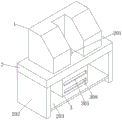
图1为本实用新型的整体结构示意图;Fig. 1 is the overall structural representation of the utility model;
图2为本实用新型的第一截面图;Fig. 2 is the first sectional view of the utility model;
图3为本实用新型的第二截面图。Fig. 3 is a second sectional view of the present utility model.
附图标记:Reference signs:
1、数控仪表车床本体;2、工作台;201、出料孔;202、支撑板;203、安装板;3、收料箱;301、侧槽;302、弹簧;303、连接块;304、滤板;305、第一排料口;306、第一清理口;307、第一阀门;308、第二排料口;309、第二清理口;310、第二阀门;4、电机箱;401、第一固定座;402、第一电机;403、第一减速机;404、第一转轴;405、转杆;406、凸轮;5、侧柱;501、滑槽;502、第二固定座;503、第二电机;504、第二减速机;505、第二转轴;506、螺纹杆;507、滑块;508、电动伸缩杆;509、清理板;510、第三固定座。1. Numerical control instrument lathe body; 2. Workbench; 201. Discharge hole; 202. Support plate; 203. Mounting plate; 3. Receiving box; 301. Side groove; 302. Spring; 303. Connection block; 304. Filter plate; 305, the first discharge port; 306, the first cleaning port; 307, the first valve; 308, the second discharge port; 309, the second cleaning port; 310, the second valve; 4, the motor box; 401, the first fixed seat; 402, the first motor; 403, the first reducer; 404, the first rotating shaft; 405, the rotating rod; 406, the cam; 5, the side column; 501, the chute; 502, the
具体实施方式Detailed ways
下面,结合附图以及具体实施方式,对实用新型做出进一步的描述:Below, in conjunction with accompanying drawing and specific embodiment, the utility model is further described:
请参阅图1-3,根据本实用新型实施例的一种数控仪表车用料屑分离器,包括数控仪表车床本体1,所述数控仪表车床本体1的底端安装有工作台2,所述工作台2的底端安装有安装板203,所述安装板203的顶端固定安装有收料箱3,所述收料箱3的内部两侧均开设有侧槽301,所述侧槽301的内部底端固定安装有弹簧302,所述弹簧302的顶端连接有连接块303,两组所述连接块303之间安装有滤板304,数控仪表车床本体1加工出来的工件以及料屑掉落到收料箱3内,通过滤板304可以对工件以及料屑进行过滤,所述收料箱3的一侧固定安装有电机箱4,所述电机箱4的内部安装有第一电机402,所述第一电机402的一侧固定安装有第一减速机403,所述第一减速机403的一侧安装有第一转轴404,所述第一转轴404的一端固定安装有转杆405,所述转杆405上固定安装有凸轮406,通过第一电机402带动第一减速机403进行转动,第一减速机403带动第一转轴404进行转动,第一转轴404带动转杆405进行转动,转杆405的转动使得凸轮406进行转动,凸轮406的转动可以间接性的将滤板304顶起,然后滤板304可以做落体运动,通过弹簧302的作用,使得滤板304可以再一定程度上进行抖动,进而可以增强过滤效果,避免大量的料屑堆积在滤板304上,影响滤板304的通过性,所述安装板203的顶端一侧还固定安装有侧柱5,所述侧柱5的一侧开设有滑槽501,所述滑槽501的内部安装有第二电机503,所述第二电机503的底端固定安装有第二减速机504,所述第二减速机504的底端安装有第二转轴505,所述第二转轴505的底端固定安装有螺纹杆506,所述螺纹杆506上螺纹连接有滑块507,所述滑块507的一侧固定安装有电动伸缩杆508,所述电动伸缩杆508的一端固定安装有清理板509,通过电动伸缩杆508的作用使得清理板509可以伸入到收料箱3的内部,进而可以对滤板304上的工件进行清理以及对收料箱3内底部的料屑进行清理,通过第二电机503带动第二减速机504进行转动,第二减速机504带动第二转轴505进行转动,第二转轴505带动螺纹杆506进行转动,螺纹杆506的转动使得滑块507可以在滑槽501内进行滑动,从而使得清理板509的高度可以被调整,使得其可以依次的对滤板304上的工件以及对收料箱3内底部的料屑进行清理。Please refer to Fig. 1-3, a kind of chip separator for numerical control instrument car according to the embodiment of the present utility model, comprises numerical control
通过本实用新型的上述方案,所述工作台2上开设有出料孔201,所述工作台2的底端两侧均固定安装有支撑板202,两组所述支撑板202之间固定安装有所述安装板203;所述连接块303滑动连接于所述侧槽301的内部,所述收料箱3的一侧开设有第一排料口305和第二排料口308,所述收料箱3的另一侧开设有第一清理口306和第二清理口309,所述第一清理口306内安装有第一阀门307,所述第二清理口309内安装有第二阀门310,所述第一排料口305和所述第一清理口306的位置相对应,所述第二排料口308和所述第二清理口309的位置相对应;所述电机箱4的内部一侧固定安装有第一固定座401,所述第一固定座401的一侧固定安装有所述第一电机402,所述第一电机402内转轴的输出端通过联轴器与所述第一减速机403内转轴的接收端相连接,所述第一减速机403内转轴的输出端通过联轴器与所述第一转轴404的一端相连接;所述滑槽501的内部顶端固定安装有第二固定座502,所述第二固定座502的底端固定安装有所述第二电机503,所述第二电机503内转轴的输出端通过联轴器与所述第二减速机504内转轴的接收端相连接,所述第二减速机504内转轴的输出端通过联轴器与所述第二转轴505的顶端相连接;所述滑槽501的内部底端固定安装有第三固定座510,所述螺纹杆506的底端与所述第三固定座510转动连接,所述滑块507滑动连接于所述滑槽501的内部。Through the above scheme of the utility model, the
本实用新型专利一种数控仪表车用料屑分离器的工作原理为:数控仪表车床本体1加工出来的工件以及料屑掉落到收料箱3内,通过滤板304可以对工件以及料屑进行过滤,在此过程中,通过第一电机402带动第一减速机403进行转动,第一减速机403带动第一转轴404进行转动,第一转轴404带动转杆405进行转动,转杆405的转动使得凸轮406进行转动,凸轮406的转动可以间接性的将滤板304顶起,然后滤板304可以做落体运动,通过弹簧302的作用,使得滤板304可以再一定程度上进行抖动,进而可以保证过滤效果,当工件与料屑分离完成之后,先启动第二电机503,通过第二电机503带动第二减速机504进行转动,第二减速机504带动第二转轴505进行转动,第二转轴505带动螺纹杆506进行转动,螺纹杆506的转动使得滑块507可以在滑槽501内进行滑动,进而使得清理板509的位置可以对准第一清理口306,然后开启第一阀门307,启动电动伸缩杆508,使得清理板509可以通过第一清理口306进入到收料箱3的内部,然后就可以将滤板304上过滤下来的工件通过第一排料口305推出,将清理板509从收料箱3内移出,再次通过第二电机503的作用使得清理板509的位置再次下降,进而使得清理板509的位置可以对准第二清理口309,然后开启第二阀门310,启动电动伸缩杆508,使得清理板509可以通过第二清理口309进入到收料箱3的内部,然后就可以将收料箱3内底部的料屑通过第二排料口308推出。The working principle of the utility model patent is a chip separator for numerical control instrument vehicle: the workpiece and material chips processed by the CNC
最后应说明的是:以上所述仅为本实用新型的优选实施例而已,并不用于限定本实用新型,尽管参照前述实施例对本实用新型进行了详细的说明,对于本领域的技术人员来说,其依然可以对前述各实施例所记载的技术方案进行修改,或者对其中部分技术特征进行等同替换。凡在本实用新型的精神和原则之内,所作的任何修改、等同替换、改进等,均应包含在本实用新型的保护范围之内。Finally, it should be noted that: the above is only a preferred embodiment of the utility model, and is not intended to limit the utility model, although the utility model has been described in detail with reference to the foregoing embodiments, for those skilled in the art , it is still possible to modify the technical solutions described in the foregoing embodiments, or perform equivalent replacements for some of the technical features. Any modification, equivalent replacement, improvement, etc. made within the spirit and principles of the present utility model shall be included in the protection scope of the present utility model.
Claims (6)
Priority Applications (1)
| Application Number | Priority Date | Filing Date | Title |
|---|---|---|---|
| CN202222258172.1U CN218800808U (en) | 2022-08-26 | 2022-08-26 | Material and scrap separator for numerical control instrument vehicle |
Applications Claiming Priority (1)
| Application Number | Priority Date | Filing Date | Title |
|---|---|---|---|
| CN202222258172.1U CN218800808U (en) | 2022-08-26 | 2022-08-26 | Material and scrap separator for numerical control instrument vehicle |
Publications (1)
| Publication Number | Publication Date |
|---|---|
| CN218800808U true CN218800808U (en) | 2023-04-07 |
Family
ID=87259865
Family Applications (1)
| Application Number | Title | Priority Date | Filing Date |
|---|---|---|---|
| CN202222258172.1U Expired - Fee Related CN218800808U (en) | 2022-08-26 | 2022-08-26 | Material and scrap separator for numerical control instrument vehicle |
Country Status (1)
| Country | Link |
|---|---|
| CN (1) | CN218800808U (en) |
-
2022
- 2022-08-26 CN CN202222258172.1U patent/CN218800808U/en not_active Expired - Fee Related
Similar Documents
| Publication | Publication Date | Title |
|---|---|---|
| CN115446651A (en) | Vertical elevating platform milling machine | |
| CN113172514A (en) | Machining is with equipment of polishing of convenient clearance | |
| CN111590430A (en) | Polishing and dust removal integrated device for electronic part manufacturing and polishing method | |
| CN108723794A (en) | A kind of cutting base and its application method of stock-removing machine | |
| CN216461763U (en) | A new type of CNC lathe | |
| CN113523606A (en) | Numerical control cutting machine convenient to clear away smear metal | |
| CN217617749U (en) | Multifunctional vertical lathe | |
| CN217393780U (en) | Make things convenient for sweeps to carry out engine lathe who collects | |
| CN216607389U (en) | Coolant liquid recovery processing device is used in milling machine processing | |
| CN208163400U (en) | A kind of surface grinding machine workbench with garbage collection structure | |
| CN211490932U (en) | A mechanical grinding device for machining | |
| CN211728540U (en) | Milling machine convenient to retrieve coolant liquid | |
| CN221909858U (en) | Radial drilling machine for machining automobile parts | |
| CN220613535U (en) | Grinding machine with conveniently replaced cutterhead | |
| CN111774972A (en) | Burr removing device for machining | |
| CN108214311B (en) | Dust collector is used in work piece processing | |
| CN216504093U (en) | Surface refining treatment equipment for miniature metal precision part | |
| CN211565280U (en) | A chip removal device for CNC machine tools | |
| CN216503459U (en) | Vertical machining center of digit control machine tool | |
| CN115194496A (en) | A high-precision vertical lathe workbench and its processing method | |
| CN209648265U (en) | A waste liquid treatment device for a vertical machining center | |
| CN209394048U (en) | A high-speed engraving and milling machine for a machine tool | |
| CN223848752U (en) | Chip removal device for numerical control lathe | |
| CN108620632B (en) | Flat die deep hole machining system | |
| CN221967711U (en) | Polishing equipment for machining |
Legal Events
| Date | Code | Title | Description |
|---|---|---|---|
| GR01 | Patent grant | ||
| GR01 | Patent grant | ||
| TR01 | Transfer of patent right |
Effective date of registration: 20231214 Address after: Room Y028, Building 2, Building E, Wangzuo Modern City, No. 35 Tangyan Road, High tech Zone, Xi'an City, Shaanxi Province, 710000, China Patentee after: Xi'an Linfengyuan Information Technology Co.,Ltd. Address before: No. 1 Caoqiao Road, Yuhang District, Hangzhou City, Zhejiang Province, 310000 Patentee before: Yan Zhen |
|
| TR01 | Transfer of patent right | ||
| CF01 | Termination of patent right due to non-payment of annual fee |
Granted publication date: 20230407 |
|
| CF01 | Termination of patent right due to non-payment of annual fee |