CN218800753U - Horizontal machining center - Google Patents
Horizontal machining center Download PDFInfo
- Publication number
- CN218800753U CN218800753U CN202223024193.3U CN202223024193U CN218800753U CN 218800753 U CN218800753 U CN 218800753U CN 202223024193 U CN202223024193 U CN 202223024193U CN 218800753 U CN218800753 U CN 218800753U
- Authority
- CN
- China
- Prior art keywords
- guide rail
- motor
- machining center
- fixed mounting
- lead screw
- Prior art date
- Legal status (The legal status is an assumption and is not a legal conclusion. Google has not performed a legal analysis and makes no representation as to the accuracy of the status listed.)
- Active
Links
- 230000007246 mechanism Effects 0.000 claims abstract description 38
- 238000009434 installation Methods 0.000 claims abstract description 15
- 238000003754 machining Methods 0.000 abstract description 6
- 230000000694 effects Effects 0.000 description 3
- 238000000034 method Methods 0.000 description 2
- 238000003801 milling Methods 0.000 description 2
- 230000008569 process Effects 0.000 description 2
- 230000002411 adverse Effects 0.000 description 1
- 230000009286 beneficial effect Effects 0.000 description 1
- 238000010586 diagram Methods 0.000 description 1
- 238000005553 drilling Methods 0.000 description 1
- 230000006872 improvement Effects 0.000 description 1
Images


Classifications
-
- Y—GENERAL TAGGING OF NEW TECHNOLOGICAL DEVELOPMENTS; GENERAL TAGGING OF CROSS-SECTIONAL TECHNOLOGIES SPANNING OVER SEVERAL SECTIONS OF THE IPC; TECHNICAL SUBJECTS COVERED BY FORMER USPC CROSS-REFERENCE ART COLLECTIONS [XRACs] AND DIGESTS
- Y02—TECHNOLOGIES OR APPLICATIONS FOR MITIGATION OR ADAPTATION AGAINST CLIMATE CHANGE
- Y02P—CLIMATE CHANGE MITIGATION TECHNOLOGIES IN THE PRODUCTION OR PROCESSING OF GOODS
- Y02P70/00—Climate change mitigation technologies in the production process for final industrial or consumer products
- Y02P70/10—Greenhouse gas [GHG] capture, material saving, heat recovery or other energy efficient measures, e.g. motor control, characterised by manufacturing processes, e.g. for rolling metal or metal working
Landscapes
- Turning (AREA)
Abstract
The utility model discloses a horizontal machining center, which comprises a column, the lower extreme fixed mounting of stand has base one, the upper end fixed mounting of stand has Z to the motor, Z has Z to the lead screw to the lower extreme movable mounting of motor, Z has installation piece one to the lower extreme fixed mounting of lead screw, Z has spindle unit to the front end sliding connection of lead screw, spindle unit's upper end fixed mounting has guide rail one, the upper end sliding mounting of guide rail one has reciprocal slide one, spindle unit's both sides fixed mounting has installation piece two, one side fixedly connected with spindle motor of installation piece two. A horizontal machining center, through reciprocating slide, guide rail one, guide rail two and revolving stage etc. realize cutting mechanism to the full aspect rotational positioning of work piece, make things convenient for cutting mechanism to carry out work, improve the machining precision of work piece, bring better use prospect.
Description
Technical Field
The utility model relates to a machining center field specifically is a horizontal machining center.
Background
The horizontal machining center is a machine tool for realizing milling machining through a mechanism with a horizontally-arranged main shaft, and due to the horizontal arrangement of the main shaft, a cutter reciprocates along the side face of a workpiece to promote effective discharge of chips.
When an existing machining center is used, a workpiece is installed on a workbench, after the workpiece is positioned at a specified position, a common large horizontal machining center realizes drilling or milling by means of movement of the workbench in the Y direction, but the structure can seriously affect the machining precision of the workpiece, certain adverse effects are brought to people in the using process, and therefore the horizontal machining center is provided.
SUMMERY OF THE UTILITY MODEL
The utility model provides a not enough to prior art, the utility model provides a horizontal machining center possesses advantages such as horizontal machining center, can effectively solve the problem in the background art.
Technical scheme
In order to achieve the above purpose, the utility model adopts the following technical scheme: the utility model provides a horizontal machining center, includes the stand, the lower extreme fixed mounting of stand has base one, the upper end fixed mounting of stand has Z to the motor, Z has Z to the lower extreme movable mounting of motor to the lead screw, Z has installation piece one to the lower extreme fixed mounting of lead screw, Z has spindle unit to the front end sliding connection of lead screw.
Preferably, the upper end fixed mounting of spindle unit has guide rail one, the upper end slidable mounting of guide rail one has reciprocating slide one, spindle unit's both sides fixed mounting has installation piece two, one side fixedly connected with spindle motor of installation piece two, the opposite side swing joint of installation piece two has the main shaft lead screw, reciprocating slide one's front end movable mounting has the activity head circle, the front end movable mounting of activity head circle has cutting mechanism.
Preferably, the front end fixed mounting of base one has base two, the both sides fixed mounting of two upper ends of base has guide rail two, the equal fixed mounting in both ends has the fixed block around two upper ends of base, the upper end slidable mounting of guide rail two has feed mechanism, the one end fixed mounting of fixed block has driving motor, the other end movable mounting of fixed block has drive lead screw.
Preferably, the feeding mechanism comprises a second reciprocating sliding plate, a workbench and a rotary table, the second reciprocating sliding plate is located at the upper end of the second guide rail, the workbench is located at the upper end of the second reciprocating sliding plate, and the rotary table is located at the upper end of the workbench.
Preferably, one side of the second base is fixedly connected with the lower end of the stand column through the first base, one end of the Z-direction motor is fixedly connected with the upper end of the first base through the stand column, one side of the Z-direction lead screw is movably connected with the front end of the stand column through the first mounting block, one side of the first mounting block is movably connected with one side of the Z-direction motor through the Z-direction lead screw, and the rear end of the spindle device is connected with the lower end of the Z-direction motor in a sliding mode through the Z-direction lead screw.
Preferably, one side of the spindle motor is movably connected with one side of the spindle screw rod through the mounting block II, one side of the reciprocating sliding plate I is slidably connected with the upper end of the spindle device through the guide rail I, the outer wall of the spindle screw rod is slidably connected with the upper end of the guide rail I through the reciprocating sliding plate I, and the rear side of the cutting mechanism is movably connected with the front end of the reciprocating sliding plate I through the movable head ring.
Preferably, the two sides of the feeding mechanism are connected with the upper end of the second base in a sliding mode through a second guide rail, the lower end of the feeding mechanism is connected with one side of the fixed block in a sliding mode through a driving screw rod, and one side of the driving motor is movably connected with one side of the driving screw rod through the fixed block.
Preferably, the lower end of the rotary table is movably connected with the upper end of a second reciprocating sliding plate through a workbench, and the lower end of the workbench is movably connected with the upper end of a second driving screw rod and the upper end of a second guide rail through the second reciprocating sliding plate.
Compared with the prior art, the utility model provides a horizontal machining center possesses following beneficial effect:
1. according to the horizontal machining center, the Z-direction motor is started to operate to drive the Z-direction screw rod to operate under the mutual matching of the Z-direction screw rod, the Z-direction motor and the spindle device, the spindle device is driven to move up and down, and therefore the reciprocating slide plate I is driven to move up and down, the cutting mechanism is driven to move up and down to be positioned, and then a workpiece on the workbench works.
2. This horizontal machining center, through the reciprocating slide one that sets up, guide rail one, spindle motor, installation piece two and the main shaft lead screw mutually support down, realize that the removal of cutting mechanism is controlled and is fixed a position, start the operation of spindle motor and drive the operation of main shaft lead screw, drive reciprocating slide one and slide from side to side on guide rail one under the operation of main shaft lead screw to drive the movable head circle of reciprocating slide one front end and the cutting mechanism side to side slip, realize cutting mechanism's location, conveniently work, easy operation to the work piece on the workstation.
3. This horizontal machining center, through the driving motor who sets up on the base two, the fixed block, under drive lead screw and the mutual cooperation of guide rail two, realize the work piece reciprocating motion of workstation, conveniently process, start driving motor operation and drive the operation of drive lead screw, it slides around on guide rail two to drive reciprocating slide two under the lead screw operation, thereby drive the work piece back-and-forth movement of workstation top, the revolving stage through the workstation top realizes the rotation to the work piece all sides, thereby make things convenient for cutting mechanism to work, the machining precision of improvement work piece.
Drawings
Fig. 1 is the overall structure schematic diagram of the horizontal machining center of the present invention.
Fig. 2 is an enlarged view of a position a in the horizontal machining center of the present invention.
Fig. 3 is an enlarged view of the position B in the horizontal machining center.
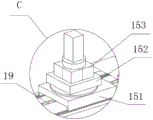
Fig. 4 is an enlarged view of the C-position in the horizontal machining center.
In the figure: 1. a column; 2. a first base; 3. a Z-direction motor; 4. a Z-direction screw rod; 5. a first mounting block; 6. a spindle device; 7. a first guide rail; 8. a first reciprocating sliding plate; 9. a spindle motor; 10. a second mounting block; 11. a main shaft screw rod; 12. a movable head ring; 13. a cutting mechanism; 14. a second base; 15. a feed mechanism; 16. a second guide rail; 17. a drive motor; 18. a fixed block; 19. driving the screw rod; 151. a second reciprocating sliding plate; 152. a work table; 153. a turntable.
Detailed Description
In order to make the technical means, creation features, achievement purposes and functions of the present invention easy to understand, the present invention is further described below with reference to the following embodiments.
As shown in figures 1-4, the horizontal machining center comprises an upright post 1, a base I2 is fixedly installed at the lower end of the upright post 1, a Z-direction motor 3 is fixedly installed at the upper end of the upright post 1, a Z-direction screw rod 4 is movably installed at the lower end of the Z-direction motor 3, an installation block I5 is fixedly installed at the lower end of the Z-direction screw rod 4, a main shaft device 6 is connected to the front end of the Z-direction screw rod 4 in a sliding mode, the Z-direction motor 3 is started to operate to drive the Z-direction screw rod 4 to operate, the main shaft device 6 is driven to move up and down, accordingly, a reciprocating sliding plate I8 is driven to move up and down, and the cutting mechanism 13 is driven to move up and down to perform positioning.
Further, a first guide rail 7 is fixedly mounted at the upper end of the main shaft device 6, a first reciprocating sliding plate 8 is slidably mounted at the upper end of the first guide rail 7, second mounting blocks 10 are fixedly mounted at two sides of the main shaft device 6, a main shaft motor 9 is fixedly connected to one side of each mounting block 10, a main shaft lead screw 11 is movably connected to the other side of each mounting block 10, a movable head ring 12 is movably mounted at the front end of each first reciprocating sliding plate 8, and a cutting mechanism 13 is movably mounted at the front end of each movable head ring 12.
Further, a second base 14 is fixedly installed at the front end of the first base 2, second guide rails 16 are fixedly installed on two sides of the upper end of the second base 14, fixed blocks 18 are fixedly installed at the front end and the rear end of the upper end of the second base 14, a feeding mechanism 15 is slidably installed at the upper end of the second guide rails 16, a driving motor 17 is fixedly installed at one end of each fixed block 18, and a driving screw rod 19 is movably installed at the other end of each fixed block 18.
Further, the feeding mechanism 15 includes a second reciprocating slide plate 151, a table 152 and a turntable 153, the second reciprocating slide plate 151 is located at the upper end of the second guide rail 16, the table 152 is located at the upper end of the second reciprocating slide plate 151, the turntable 153 is located at the upper end of the table 152, and the workpiece is rotated in all directions by the turntable 153 above the table 152.
Furthermore, one side of the second base 14 is fixedly connected with the lower end of the upright post 1 through the first base 2, one end of the Z-direction motor 3 is fixedly connected with the upper end of the first base 2 through the upright post 1, one side of the Z-direction screw rod 4 is movably connected with the front end of the upright post 1 through the first mounting block 5, one side of the first mounting block 5 is movably connected with one side of the Z-direction motor 3 through the Z-direction screw rod 4, and the rear end of the spindle device 6 is slidably connected with the lower end of the Z-direction motor 3 through the Z-direction screw rod 4.
Furthermore, one side of a spindle motor 9 is movably connected with one side of a spindle screw 11 through a mounting block II 10, one side of a reciprocating sliding plate I8 is slidably connected with the upper end of a spindle device 6 through a guide rail I7, the outer wall of the spindle screw 11 is slidably connected with the upper end of the guide rail I7 through the reciprocating sliding plate I8, the rear side of a cutting mechanism 13 is movably connected with the front end of the reciprocating sliding plate I8 through a movable head ring 12, the cutting mechanism 13 is moved leftwards and rightwards to be positioned, the spindle motor 9 is started to operate to drive the spindle screw 11 to operate, the reciprocating sliding plate I8 is driven to slide leftwards and rightwards on the guide rail I7 under the operation of the spindle screw 11, so that the movable head ring 12 at the front end of the reciprocating sliding plate I8 and the cutting mechanism 13 are driven to slide leftwards and rightwards, and the positioning of the cutting mechanism 13 is realized.
Furthermore, two sides of the feeding mechanism 15 are slidably connected with the upper end of the second base 14 through a second guide rail 16, the lower end of the feeding mechanism 15 is slidably connected with one side of the fixed block 18 through a driving screw rod 19, one side of the driving motor 17 is movably connected with one side of the driving screw rod 19 through the fixed block 18, the driving motor 17 is started to operate to drive the driving screw rod 19 to operate, and the reciprocating sliding plate second 151 is driven to slide back and forth on the second guide rail 16 under the operation of the driving screw rod 19.
Further, the lower end of the rotary table 153 is movably connected with the upper end of the second reciprocating sliding plate 151 through the workbench 152, the lower end of the workbench 152 is movably connected with the upper end of the second driving screw rod 19 and the upper end of the second guide rail 16 through the second reciprocating sliding plate 151, and the second reciprocating sliding plate 151 slides back and forth on the second guide rail 16, so that a workpiece above the workbench 152 is driven to move back and forth, and the workpiece is rotated in all directions through the rotary table 153 above the workbench 152.
When the horizontal machining center is used, firstly, under the mutual matching of a Z-direction screw rod 4, a Z-direction motor 3 and a main shaft device 6 which are arranged at the front end of an upright post 1, the operation of the Z-direction motor 3 is started to drive the Z-direction screw rod 4 to operate, the main shaft device 6 is driven to move up and down, so that a reciprocating slide plate I8 is driven to move up and down, the up and down movement of a cutting mechanism 13 is realized to position, then a workpiece on a worktable 152 works, under the mutual matching of the arranged reciprocating slide plate I8, a guide rail I7, a main shaft motor 9, a mounting block II 10 and a main shaft screw rod 11, the left and right movement of the cutting mechanism 13 is realized to position, the operation of the main shaft motor 9 is started to drive the main shaft screw rod 11 to operate, the reciprocating slide plate I8 is driven to slide left and right on the guide rail I7 under the operation of the main shaft screw rod 11, the movable head ring 12 at the front end of the first reciprocating sliding plate 8 and the cutting mechanism 13 are driven to slide left and right, the positioning of the cutting mechanism 13 is achieved, work on a workpiece on the workbench 152 is facilitated, the operation is simple, the reciprocating motion of the workpiece on the workbench 152 is achieved under the mutual matching of the driving motor 17, the fixing block 18, the driving screw rod 19 and the guide rail two 16 which are arranged on the base two 14, the machining is facilitated, the driving motor 17 is started to operate to drive the driving screw rod 19 to operate, the reciprocating sliding plate two 151 is driven to slide back and forth on the guide rail two 16 under the operation of the driving screw rod 19, the workpiece above the workbench 152 is driven to move back and forth, the workpiece is rotated in all directions through the rotary table 153 above the workbench 152, the cutting mechanism 13 is facilitated to work, and the machining precision of the workpiece is improved.
The basic principles and the main features of the invention and the advantages of the invention have been shown and described above. It will be understood by those skilled in the art that the present invention is not limited to the above embodiments, and that the foregoing embodiments and descriptions are provided only to illustrate the principles of the present invention without departing from the spirit and scope of the present invention. The scope of the invention is defined by the appended claims and equivalents thereof.
Claims (8)
1. The utility model provides a horizontal machining center, includes stand (1), its characterized in that: the lower extreme fixed mounting of stand (1) has base (2), the upper end fixed mounting of stand (1) has Z to motor (3), Z has Z to lead screw (4) to the lower extreme movable mounting of motor (3), Z has installation piece (5) to the lower extreme fixed mounting of lead screw (4), Z has spindle unit (6) to the front end sliding connection of lead screw (4).
2. The horizontal machining center according to claim 1, wherein: the utility model discloses a reciprocating type lathe spindle, including main shaft device (6), the upper end fixed mounting of main shaft device (6) has guide rail (7), the upper end slidable mounting of guide rail (7) has reciprocating slide (8), the both sides fixed mounting of main shaft device (6) has installation piece two (10), one side fixedly connected with spindle motor (9) of installation piece two (10), the opposite side swing joint of installation piece two (10) has main shaft lead screw (11), the front end movable mounting of reciprocating slide (8) has movable head circle (12), the front end movable mounting of movable head circle (12) has cutting mechanism (13).
3. The horizontal machining center according to claim 1, wherein: the utility model discloses a drive mechanism, including base (2), both sides fixed mounting have guide rail two (16), the front end fixed mounting of base (2) has base two (14), the both ends fixed mounting all has fixed block (18) around base two (14) upper end, the upper end slidable mounting of guide rail two (16) has feed mechanism (15), the one end fixed mounting of fixed block (18) has driving motor (17), the other end movable mounting of fixed block (18) has drive lead screw (19).
4. The horizontal machining center according to claim 3, wherein: feed mechanism (15) are including two (151) of reciprocating slide, workstation (152) and revolving stage (153), two (151) of reciprocating slide are located the upper end of two (16) of guide rail, workstation (152) are located the upper end of two (151) of reciprocating slide, revolving stage (153) are located the upper end of workstation (152).
5. The horizontal machining center according to claim 3, wherein: one side of base two (14) is through the lower extreme fixed connection of base (2) and stand (1), Z passes through the upper end fixed connection of stand (1) and base (2) to the one end of motor (3), Z passes through the front end swing joint of installation piece (5) and stand (1) to one side of lead screw (4), one side of installation piece (5) is through Z to lead screw (4) and one side swing joint of Z to motor (3), the rear end of spindle unit (6) passes through Z to lead screw (4) and Z to the lower extreme sliding connection of motor (3).
6. The horizontal machining center according to claim 2, wherein: one side of the spindle motor (9) is movably connected with one side of a spindle screw rod (11) through a mounting block II (10), one side of a reciprocating sliding plate I (8) is slidably connected with the upper end of a spindle device (6) through a guide rail I (7), the outer wall of the spindle screw rod (11) is slidably connected with the upper end of the guide rail I (7) through the reciprocating sliding plate I (8), and the rear side of the cutting mechanism (13) is movably connected with the front end of the reciprocating sliding plate I (8) through a movable head ring (12).
7. The horizontal machining center according to claim 3, wherein: the two sides of the feeding mechanism (15) are connected with the upper end of the second base (14) in a sliding mode through a second guide rail (16), the lower end of the feeding mechanism (15) is connected with one side of the fixing block (18) in a sliding mode through the driving screw rod (19), and one side of the driving motor (17) is movably connected with one side of the driving screw rod (19) through the fixing block (18).
8. The horizontal machining center according to claim 4, wherein: the lower end of the rotary table (153) is movably connected with the upper end of a second reciprocating sliding plate (151) through a workbench (152), and the lower end of the workbench (152) is movably connected with the upper ends of a second driving screw rod (19) and a second guide rail (16) through the second reciprocating sliding plate (151).
Priority Applications (1)
| Application Number | Priority Date | Filing Date | Title |
|---|---|---|---|
| CN202223024193.3U CN218800753U (en) | 2022-11-14 | 2022-11-14 | Horizontal machining center |
Applications Claiming Priority (1)
| Application Number | Priority Date | Filing Date | Title |
|---|---|---|---|
| CN202223024193.3U CN218800753U (en) | 2022-11-14 | 2022-11-14 | Horizontal machining center |
Publications (1)
| Publication Number | Publication Date |
|---|---|
| CN218800753U true CN218800753U (en) | 2023-04-07 |
Family
ID=87270436
Family Applications (1)
| Application Number | Title | Priority Date | Filing Date |
|---|---|---|---|
| CN202223024193.3U Active CN218800753U (en) | 2022-11-14 | 2022-11-14 | Horizontal machining center |
Country Status (1)
| Country | Link |
|---|---|
| CN (1) | CN218800753U (en) |
-
2022
- 2022-11-14 CN CN202223024193.3U patent/CN218800753U/en active Active
Similar Documents
| Publication | Publication Date | Title |
|---|---|---|
| CN201856088U (en) | Moving beam type numerical control gantry combined machine tool | |
| CN101961836B (en) | Numerically-controlled gantry type vertical and horizontal combined machine tool | |
| CN201792194U (en) | Numerical control gantry vertical-horizontal combined machine tool | |
| CN201799851U (en) | Numerical-control vertical combined gantry machine tool | |
| CN202037447U (en) | Vertical machining center with fixed worktable | |
| CN101966650A (en) | Numerical control gantry vertical combined machine tool | |
| CN207326449U (en) | A kind of parallel lathe of double five-axle linkage | |
| CN109909527B (en) | Multi-shaft multi-position milling machine and working mode thereof | |
| CN114654022A (en) | Multi-station full-automatic saw blade grinding machine | |
| CN220127729U (en) | Vertical pull-up broaching machine bedstead | |
| CN112589539A (en) | Numerical control vertical and horizontal compound machine | |
| CN211440360U (en) | Numerical control multifunctional five-axis machining center | |
| CN220782350U (en) | Vertical milling machine for machining | |
| CN202062247U (en) | Horizontal type processing center with fixed worktable | |
| CN219152566U (en) | High efficiency water jet cutting device | |
| CN215316910U (en) | Synchronous boring and milling machine | |
| CN217166644U (en) | Planer type milling machine | |
| CN207510099U (en) | The vertical engraving machine of large-scale three dimensional | |
| CN118180891A (en) | A three-station gantry CNC machining machine for rice milling sand rollers | |
| CN110744319A (en) | Bedroom boring machine of adjustable material angle | |
| CN215749665U (en) | Numerical control drilling device | |
| CN213318807U (en) | Multi-station machine tool equipment | |
| CN221773945U (en) | A CNC machining center based on planer | |
| CN214392661U (en) | An economical horizontal machining center | |
| CN213857080U (en) | Novel horizontal type main shaft box device |
Legal Events
| Date | Code | Title | Description |
|---|---|---|---|
| GR01 | Patent grant | ||
| GR01 | Patent grant |