CN218785385U - Automatic unloader that goes up of duplex - Google Patents
Automatic unloader that goes up of duplex Download PDFInfo
- Publication number
- CN218785385U CN218785385U CN202222186328.XU CN202222186328U CN218785385U CN 218785385 U CN218785385 U CN 218785385U CN 202222186328 U CN202222186328 U CN 202222186328U CN 218785385 U CN218785385 U CN 218785385U
- Authority
- CN
- China
- Prior art keywords
- vertical
- guide rail
- traverse
- chuck
- longitudinal
- Prior art date
- Legal status (The legal status is an assumption and is not a legal conclusion. Google has not performed a legal analysis and makes no representation as to the accuracy of the status listed.)
- Active
Links
Images


Landscapes
- Feeding Of Workpieces (AREA)
Abstract
本实用新型公开了一种双机自动上下料装置,包括设于两台数控机床之间的安装架,所述安装架的顶部设有横梁,所述横梁上设有水平滑动架,所述水平滑动架在横梁上左右往复移动,所述水平滑动架上设有纵梁,所述纵梁在水平滑动架上前后往复移动,所述纵梁前端设有竖向滑动架,所述竖向滑动架上设有竖梁,所述竖梁在竖向滑动架上上下往复移动,所述安装架上设有用于放置物料盘的工作台,所述竖梁下端设有抓取机构,所述抓取机构用于从物料盘上抓取待加工件以及从机床卡盘上夹取已加工件。通过采用该装置可以实现两台数控机床的自动上下料,无需再由人工进行装夹以及卸料,降低了人工劳动强度及成本。
The utility model discloses a dual-machine automatic loading and unloading device, which comprises a mounting frame arranged between two numerically controlled machine tools. The sliding frame reciprocates left and right on the beam, the horizontal sliding frame is provided with a longitudinal beam, the longitudinal beam moves back and forth on the horizontal sliding frame, the front end of the longitudinal beam is provided with a vertical sliding frame, and the vertical sliding There is a vertical beam on the frame, and the vertical beam reciprocates up and down on the vertical sliding frame. The picking mechanism is used to grab the workpiece to be processed from the material tray and the processed workpiece from the chuck of the machine tool. By adopting the device, the automatic loading and unloading of two numerical control machine tools can be realized, without manual clamping and unloading, which reduces the labor intensity and cost.
Description
技术领域technical field
本实用新型涉及工艺装备领域,具体涉及一种双机自动上下料装置。The utility model relates to the field of process equipment, in particular to a dual-machine automatic loading and unloading device.
背景技术Background technique
数控机床是一种装有程序控制系统的自动化机床,较好地解决了复杂、精密、小批量、多品种的零件加工问题,是一种柔性的、高效能的自动化机床。目前采用卧式数控机床批量加工较小的圆盘或轴类工件时,通常是由工人进行上下料操作,具体是工人将待加工件装夹在机床卡盘上,待数控机床加工完毕后工人再将已加工件卸下,如此循环上下料,这样每台设备运行时都要配备一个工人,不仅会增加人工成本,而且劳动强度也大。为此,需要研发一种双机自动上下料装置,将其设置于两个数控机床之间,以便实现这两台数控机床的工件自动上下料操作。CNC machine tool is an automatic machine tool equipped with a program control system, which can better solve the problem of complex, precise, small batch and multi-variety parts processing. It is a flexible and high-efficiency automatic machine tool. At present, when horizontal CNC machine tools are used to process smaller disc or shaft workpieces in batches, workers usually perform loading and unloading operations. Specifically, workers clamp the workpieces to be processed on the machine chuck, and after the CNC machine tool is finished, the workers Then the processed parts are unloaded, and the materials are loaded and unloaded in this way, so that each equipment must be equipped with a worker when it is running, which will not only increase the labor cost, but also increase the labor intensity. For this reason, it is necessary to develop a dual-machine automatic loading and unloading device, which is arranged between two CNC machine tools, so as to realize the automatic loading and unloading operation of the workpieces of the two CNC machine tools.
实用新型内容Utility model content
本实用新型目的在于:针对目前采用卧式数控机床批量加工较小的圆盘或轴类工件时由人工进行上下料操作的问题,提供一种双机自动上下料装置,通过采用该装置可以实现相邻两台数控机床的自动上料以及下料,无需再由人工进行装夹以及卸料,大大降低了人工劳动强度。The purpose of the utility model is to provide a dual-machine automatic loading and unloading device for the problem of manual loading and unloading operations when using horizontal numerical control machine tools to process smaller discs or shaft workpieces in batches. The automatic loading and unloading of two adjacent CNC machine tools does not require manual clamping and unloading, which greatly reduces the labor intensity.
为了实现上述目的,本实用新型采用的技术方案为:In order to achieve the above object, the technical solution adopted by the utility model is:
一种双机自动上下料装置,包括设于两台数控机床之间的安装架,所述安装架的顶部设有横梁,所述横梁上设有水平滑动架,所述水平滑动架在横梁上左右往复移动,所述水平滑动架上设有纵梁,所述纵梁在水平滑动架上前后往复移动,所述纵梁前端设有竖向滑动架,所述竖向滑动架上设有竖梁,所述竖梁在竖向滑动架上上下往复移动,所述安装架上设有用于放置物料盘的工作台,所述竖梁下端设有抓取机构,所述抓取机构用于从物料盘上抓取待加工件以及从机床卡盘上夹取已加工件。A double-machine automatic loading and unloading device, including a mounting frame arranged between two numerically controlled machine tools, a crossbeam is arranged on the top of the mounting frame, a horizontal sliding frame is arranged on the crossbeam, and the horizontal sliding frame is mounted on the crossbeam Move back and forth left and right, the horizontal sliding frame is provided with a longitudinal beam, the longitudinal beam moves back and forth on the horizontal sliding frame, the front end of the longitudinal beam is provided with a vertical sliding frame, and the vertical sliding frame is provided with a vertical The vertical beam reciprocates up and down on the vertical sliding frame, the mounting frame is provided with a workbench for placing material trays, and the lower end of the vertical beam is provided with a grabbing mechanism, and the grabbing mechanism is used to Grab the workpiece to be processed on the material tray and clamp the processed workpiece from the chuck of the machine tool.
本实用新型通过水平滑动架在横梁上滑动、纵梁及竖向滑动架在水平滑动架上滑动、竖梁在竖向滑动架上滑动,使得抓取机构能沿空间三轴移动位置,使用时将物料盘置于工作台上,通过抓取机构从物料盘上抓取待加工件后,移动到机床卡盘处完成已加工件的夹取,同时将待加工件装夹在机床卡盘上,然后再将已加工件送回物料盘中;通过采用该装置可以实现两台数控机床的自动上下料,无需再由人工进行装夹以及卸料,降低了人工劳动强度及成本。In the utility model, the horizontal sliding frame slides on the crossbeam, the longitudinal beam and the vertical sliding frame slide on the horizontal sliding frame, and the vertical beam slides on the vertical sliding frame, so that the grabbing mechanism can move along three axes in the space. Place the material tray on the workbench, grab the parts to be processed from the material tray through the grabbing mechanism, move to the chuck of the machine tool to complete the clamping of the processed parts, and clamp the parts to be processed on the machine tool chuck at the same time , and then send the processed parts back to the material tray; through the use of this device, the automatic loading and unloading of two CNC machine tools can be realized, and there is no need for manual clamping and unloading, which reduces the labor intensity and cost.
作为本实用新型的优选方案,所述水平滑动架与横梁之间设有横移机构,所述横移机构包括设于横梁上的横移导轨条和横移齿条,以及设于水平滑动架上的横移导轨座和横移伺服电机,所述横移导轨座与横移导轨条相配合,所述横移伺服电机的输出轴上设有横移驱动齿轮,所述横移驱动齿轮与横移齿条相啮合。As a preferred solution of the present utility model, a traversing mechanism is provided between the horizontal sliding frame and the beam, and the traversing mechanism includes a traversing guide rail bar and a traversing rack arranged on the beam, and a horizontal sliding frame The traversing guide rail seat and the traversing servo motor on the traversing guide rail seat are matched with the traversing guide rail bar, and the output shaft of the traversing servo motor is provided with a traversing driving gear, and the traversing driving gear and The traversing racks mesh.
作为本实用新型的优选方案,所述纵梁与水平滑动架之间设有纵移机构,所述纵移机构包括设于纵梁上的纵移导轨条和纵移齿条,以及设于水平滑动架上的纵移导轨座和纵移伺服电机,所述纵移导轨座与纵移导轨条相配合,所述纵移伺服电机的输出轴上设有纵移驱动齿轮,所述纵移驱动齿轮与纵移齿条相啮合。As a preferred solution of the present utility model, a longitudinal movement mechanism is provided between the longitudinal beam and the horizontal sliding frame, and the longitudinal movement mechanism includes a longitudinal movement guide rail bar and a longitudinal movement rack arranged on the longitudinal beam, and The longitudinal movement guide rail seat and the longitudinal movement servo motor on the sliding frame, the longitudinal movement guide rail seat is matched with the longitudinal movement guide rail bar, the output shaft of the longitudinal movement servo motor is provided with a longitudinal movement driving gear, and the longitudinal movement driving The gear meshes with the longitudinal rack.
作为本实用新型的优选方案,所述竖梁与竖向滑动架之间设有竖移机构,所述竖移机构包括设于竖梁上的竖移导轨条和竖移齿条,以及设于竖向滑动架上的竖移导轨座和竖移伺服电机,所述竖移导轨座与竖移导轨条相配合,所述竖移伺服电机的输出轴上设有竖移驱动齿轮,所述竖移驱动齿轮与竖移齿条相啮合。As a preferred solution of the present utility model, a vertical movement mechanism is provided between the vertical beam and the vertical sliding frame, and the vertical movement mechanism includes a vertical movement guide rail bar and a vertical movement rack arranged on the vertical beam, and a The vertically moving guide rail seat and the vertically moving servo motor on the vertical sliding frame, the vertically moving guide rail seat is matched with the vertically moving guide rail bar, the output shaft of the vertically moving servo motor is provided with a vertically moving driving gear, and the vertically moving The shift drive gear is meshed with the vertical shift rack.
作为本实用新型的优选方案,所述抓取机构包括基座、回转执行器和安装座,所述基座与竖梁下端相连,所述回转执行器的固定部分与基座相连,所述回转执行器的回转中心线与竖直平面呈45°夹角,所述回转执行器的回转部分与安装座相连,所述安装座上以回转中心线为基准对称设有两个卡盘,两个所述卡盘的中心线相互垂直并且与回转执行器的回转中心线共面。该抓取机构安装后通过竖直的卡盘从物料盘中自动夹取待加工件,然后移动至机床卡盘处,通过水平的卡盘自动夹取机床卡盘上的已加工件,然后回转执行器动作使安装座转动180°,从而使两个卡盘的位置互换,以便将待加工件放入机床卡盘上实现上料,再将抓取机构移动至物料盘上方,松开竖直的卡盘后将已加工件放入物料盘中;由于采用了两个卡盘,提高了上下料的效率。As a preferred solution of the present utility model, the grabbing mechanism includes a base, a rotary actuator and a mounting seat, the base is connected to the lower end of the vertical beam, the fixed part of the rotary actuator is connected to the base, and the rotary actuator The rotary center line of the actuator forms an included angle of 45° with the vertical plane, and the rotary part of the rotary actuator is connected to the mounting seat, and the mounting seat is symmetrically provided with two chucks based on the rotary center line, and two The centerlines of the chucks are perpendicular to each other and coplanar with the rotary centerline of the rotary actuator. After the grabbing mechanism is installed, the workpiece to be processed is automatically clamped from the material tray through the vertical chuck, and then moved to the chuck of the machine tool, and the processed workpiece on the chuck of the machine tool is automatically clamped through the horizontal chuck, and then rotated The action of the actuator makes the mounting seat rotate 180°, so that the positions of the two chucks are exchanged, so that the workpiece to be processed can be placed on the chuck of the machine tool for loading, and then the grabbing mechanism is moved to the top of the material tray, and the vertical clamp is released. After the straight chuck, put the processed parts into the material tray; due to the use of two chucks, the efficiency of loading and unloading is improved.
作为本实用新型的优选方案,在任意一个卡盘上设有推料机构,所述推料机构包括支撑环、若干导向杆和推料板,所述支撑环与卡盘相连,所述导向杆周向均布在支撑环上并与卡爪位置均匀错开,所述推料板包括从卡盘中心沿径向延伸的若干连接条,每个连接条与导向杆滑动连接,所述导向杆上套设有弹簧,所述弹簧位于连接条与支撑环之间。通过带有推料机构的卡盘来夹持待加工件,取料时物料盘中待加工件会使推料板向卡盘靠近并使弹簧同步压缩,以便卡盘能够夹持住待加工件,装夹时松开卡盘在弹簧作用下,推料板复位将待加工件向机床卡盘方向推动,从而更加方便厚度不大的圆形工件装夹。As a preferred solution of the present utility model, a pusher mechanism is provided on any chuck, and the pusher mechanism includes a support ring, a plurality of guide rods and a pusher plate, the support ring is connected with the chuck, and the guide rod The circumferential direction is evenly distributed on the support ring and evenly staggered with the position of the jaws. The pushing plate includes several connecting bars extending radially from the center of the chuck. Each connecting bar is slidably connected with the guide rod, and the guide rod is sleeved There is a spring, which is located between the connecting strip and the support ring. The workpiece to be processed is clamped by a chuck with a pushing mechanism. When the material is taken out, the workpiece to be processed in the material tray will make the pushing plate approach the chuck and the spring will be compressed synchronously, so that the chuck can clamp the workpiece to be processed. , When clamping, loosen the chuck and under the action of the spring, the pusher plate resets to push the workpiece to be processed towards the chuck of the machine tool, which makes it more convenient to clamp circular workpieces with small thickness.
综上所述,由于采用了上述技术方案,本实用新型的有益效果是:In summary, due to the adoption of the above technical solution, the beneficial effects of the utility model are:
本实用新型通过水平滑动架在横梁上滑动、纵梁及竖向滑动架在水平滑动架上滑动、竖梁在竖向滑动架上滑动,使得抓取机构能沿空间三轴移动位置,使用时将物料盘置于工作台上,通过抓取机构从物料盘上抓取待加工件后,移动到机床卡盘处完成已加工件的夹取,同时将待加工件装夹在机床卡盘上,然后再将已加工件送回物料盘中;通过采用该装置可以实现两台数控机床的自动上下料,无需再由人工进行装夹以及卸料,降低了人工劳动强度及成本。In the utility model, the horizontal sliding frame slides on the crossbeam, the longitudinal beam and the vertical sliding frame slide on the horizontal sliding frame, and the vertical beam slides on the vertical sliding frame, so that the grabbing mechanism can move along three axes in the space. Place the material tray on the workbench, grab the parts to be processed from the material tray through the grabbing mechanism, move to the chuck of the machine tool to complete the clamping of the processed parts, and clamp the parts to be processed on the machine tool chuck at the same time , and then send the processed parts back to the material tray; through the use of this device, the automatic loading and unloading of two CNC machine tools can be realized, and there is no need for manual clamping and unloading, which reduces the labor intensity and cost.
附图说明Description of drawings
图1为本实用新型中的双机自动上下料装置正视图。Fig. 1 is the front view of the dual-machine automatic loading and unloading device in the utility model.
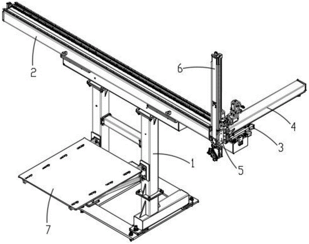
图2为本实用新型中的双机自动上下料装置立体图。Fig. 2 is a perspective view of the dual-machine automatic loading and unloading device in the utility model.
图3为图2中的横梁组件局部示意图。FIG. 3 is a partial schematic diagram of the beam assembly in FIG. 2 .
图4为图2中的纵梁组件局部示意图。FIG. 4 is a partial schematic diagram of the longitudinal beam assembly in FIG. 2 .
图5为图4另一视角示意图。FIG. 5 is a schematic diagram of another viewing angle of FIG. 4 .
图6为图4中隐藏部分零件后示意图。Fig. 6 is a schematic diagram after hiding some parts in Fig. 4 .
图7为图2中的竖梁组件局部示意图。FIG. 7 is a partial schematic view of the vertical beam assembly in FIG. 2 .
图8为抓取机构正视图。Figure 8 is a front view of the grabbing mechanism.
图9为抓取机构立体图。Fig. 9 is a perspective view of the grabbing mechanism.
图10为本实用新型中的双机自动上下料装置安装立体图。Fig. 10 is an installation perspective view of the dual-machine automatic loading and unloading device in the utility model.
图中标记:1-安装架,2-横梁,3-水平滑动架,4-纵梁,5-竖向滑动架,6-竖梁,7-工作台,8-横移导轨条,9-横移齿条,10-横移导轨座,11-横移伺服电机,12-横移驱动齿轮,13-纵移导轨条,14-纵移齿条,15-纵移导轨座,16-纵移伺服电机,17-纵移驱动齿轮,18-竖移导轨条,19-竖移齿条,20-竖移导轨座,21-竖移伺服电机,22-竖移驱动齿轮,23-基座,24-回转执行器,25-安装座,26-卡盘,27-支撑环,28-导向杆,29-推料板,30-弹簧,31-固定条,32-限位杆,33-限位块,34-数控机床。Marks in the figure: 1-installation frame, 2-beam, 3-horizontal sliding frame, 4-longitudinal beam, 5-vertical sliding frame, 6-vertical beam, 7-workbench, 8-transverse guide rail, 9- Traverse rack, 10-transverse guide rail seat, 11-transverse servo motor, 12-transverse drive gear, 13-vertical guide rail, 14-vertical rack, 15-vertical guide rail seat, 16-longitudinal Servo motor, 17-vertical drive gear, 18-vertical guide rail, 19-vertical rack, 20-vertical guide seat, 21-vertical servo motor, 22-vertical drive gear, 23-base , 24-rotary actuator, 25-mounting seat, 26-chuck, 27-support ring, 28-guide rod, 29-push plate, 30-spring, 31-fixing bar, 32-limit rod, 33- Limit block, 34-CNC machine.
具体实施方式Detailed ways
下面结合附图,对本实用新型作详细的说明。Below in conjunction with accompanying drawing, the utility model is described in detail.
为了使本实用新型的目的、技术方案及优点更加清楚明白,以下结合附图及实施例,对本实用新型进行进一步详细说明。应当理解,此处所描述的具体实施例仅用以解释本实用新型,并不用于限定本实用新型。In order to make the purpose, technical solution and advantages of the utility model clearer, the utility model will be further described in detail below in conjunction with the accompanying drawings and embodiments. It should be understood that the specific embodiments described here are only used to explain the utility model, and are not intended to limit the utility model.
实施例Example
本实施例提供一种双机自动上下料装置;This embodiment provides a dual-machine automatic loading and unloading device;
如图1-图10所示,本实施例中的双机自动上下料装置,包括设于两台数控机床34之间的安装架1,所述安装架1的顶部设有横梁2,所述横梁2上设有水平滑动架3,所述水平滑动架3在横梁2上左右往复移动(以面向机床正面为参考),所述水平滑动架3上设有纵梁4,所述纵梁4在水平滑动架3上前后往复移动(以面向机床正面为参考),所述纵梁4前端设有竖向滑动架5,所述竖向滑动架5上设有竖梁6,所述竖梁6在竖向滑动架5上上下往复移动(以面向机床正面为参考),所述安装架1上设有用于放置物料盘的工作台7,所述竖梁6下端设有抓取机构,所述抓取机构用于从物料盘上抓取待加工件以及从机床卡盘上夹取已加工件。As shown in Figures 1-10, the double-machine automatic loading and unloading device in the present embodiment includes a mounting frame 1 arranged between two numerically controlled
本实用新型通过水平滑动架在横梁上滑动、纵梁及竖向滑动架在水平滑动架上滑动、竖梁在竖向滑动架上滑动,使得抓取机构能沿空间三轴移动位置,使用时将物料盘置于工作台上,通过抓取机构从物料盘上抓取待加工件后,移动到机床卡盘处完成已加工件的夹取,同时将待加工件装夹在机床卡盘上,然后再将已加工件送回物料盘中;通过采用该装置可以实现两台数控机床的自动上下料,无需再由人工进行装夹以及卸料,降低了人工劳动强度及成本。In the utility model, the horizontal sliding frame slides on the crossbeam, the longitudinal beam and the vertical sliding frame slide on the horizontal sliding frame, and the vertical beam slides on the vertical sliding frame, so that the grabbing mechanism can move along three axes in the space. Place the material tray on the workbench, grab the parts to be processed from the material tray through the grabbing mechanism, move to the chuck of the machine tool to complete the clamping of the processed parts, and clamp the parts to be processed on the machine tool chuck at the same time , and then send the processed parts back to the material tray; through the use of this device, the automatic loading and unloading of two CNC machine tools can be realized, and there is no need for manual clamping and unloading, which reduces the labor intensity and cost.
本实施例中,所述水平滑动架3与横梁2之间设有横移机构,所述横移机构包括设于横梁2上的横移导轨条8和横移齿条9,以及设于水平滑动架3上的横移导轨座10和横移伺服电机11,所述横移导轨座10与横移导轨条8相配合,所述横移伺服电机11的输出轴上设有横移驱动齿轮12,所述横移驱动齿轮12与横移齿条9相啮合。使用时通过横移伺服电机带动横移驱动齿轮转动,通过横移驱动齿轮与横移齿条啮合作用,进而带动水平滑动架沿横移导轨条进行左右直线滑动。In this embodiment, a traversing mechanism is provided between the horizontal sliding
本实施例中,所述纵梁4与水平滑动架3之间设有纵移机构,所述纵移机构包括设于纵梁4上的纵移导轨条13和纵移齿条14,以及设于水平滑动架3上的纵移导轨座15和纵移伺服电机16,所述纵移导轨座15与纵移导轨条13相配合,所述纵移伺服电机16的输出轴上设有纵移驱动齿轮17,所述纵移驱动齿轮17与纵移齿条14相啮合。使用时通过纵移伺服电机带动纵移驱动齿轮转动,通过纵移驱动齿轮与纵移齿条啮合作用,进而带动纵梁沿纵移导轨座进行前后直线滑动。In this embodiment, a longitudinal movement mechanism is provided between the
本实施例中,所述竖梁6与竖向滑动架5之间设有竖移机构,所述竖移机构包括设于竖梁6上的竖移导轨条18和竖移齿条19,以及设于竖向滑动架5上的竖移导轨座20和竖移伺服电机21,所述竖移导轨座20与竖移导轨条18相配合,所述竖移伺服电机21的输出轴上设有竖移驱动齿轮22,所述竖移驱动齿轮22与竖移齿条19相啮合。使用时通过竖移伺服电机带动竖移驱动齿轮转动,通过竖移驱动齿轮与竖移齿条啮合作用,进而带动竖梁沿竖移导轨座进行竖向直线滑动。In this embodiment, a vertical movement mechanism is provided between the
本实施例中,所述抓取机构包括基座23、回转执行器24和安装座25,所述基座23与竖梁6下端相连,所述回转执行器24的固定部分与基座23相连,所述回转执行器24的回转中心线与竖直平面呈45°夹角,所述回转执行器24的回转部分与安装座25相连,所述安装座25上以回转中心线为基准对称设有两个卡盘26,两个所述卡盘26的中心线相互垂直并且与回转执行器24的回转中心线共面。该抓取机构安装后一个卡盘中心线处于竖直状态,另一个卡盘中心线处于水平状态,通过竖直的卡盘从物料盘中自动夹取待加工件,然后将抓取机构移动至机床卡盘处,并使水平的卡盘与机床卡盘中心相对,通过水平的卡盘自动夹取机床卡盘上的已加工件,然后通过回转执行器动作使安装座转动180°,从而使两个卡盘的位置互换,以便将待加工件放入机床卡盘上实现上料,而已加工件此时位于竖直的卡盘上,再将抓取机构移动至物料盘上方,松开卡盘后将已加工件放入物料盘中;由于采用了两个卡盘,提高了上下料的效率。具体地,所述回转执行器24为旋转气缸,所述卡盘26为气动三爪卡盘。In this embodiment, the grabbing mechanism includes a
本实施例中,在任意一个卡盘26上设有推料机构,所述推料机构包括支撑环27、三个导向杆28和推料板29,所述支撑环27与卡盘26相连,所述导向杆28周向均布在支撑环27上并与卡盘26上的卡爪位置均匀错开,所述推料板29包括从卡盘26中心沿径向延伸的三个连接条,每个连接条与导向杆28滑动连接,所述导向杆28上套设有弹簧30,所述弹簧30位于连接条与支撑环27之间。由于在上料时两个卡盘会互换位置,即装夹前待加工件始终处于水平的卡盘上,当工件厚度不大时,松开卡盘后不便于机床卡盘夹持工件,通过在卡盘上设置推料机构,以该卡盘来夹持待加工件,取料时物料盘中待加工件会使推料板向卡盘靠近并使弹簧同步压缩,以便卡盘能够夹持住待加工件,装夹时松开卡盘在弹簧作用下,推料板复位将待加工件向机床卡盘方向推动,从而更加方便厚度不大的圆形工件装夹。具体地,所述推料板上的每个连接条分别位于卡盘上的相邻两个卡爪中间,推料板上与卡爪相对的位置处开有让位缺口,以防止在推料板向卡盘靠近时与卡爪发生干涉。In this embodiment, a material pushing mechanism is provided on any
本实施例中,所述回转执行器24与安装座25之间设有限位机构,所述限位机构包括固定条31、两个限位杆32、限位块33,所述固定条31与回转执行器24的固定部分相连,所述限位杆32分别安装于固定条31的两端位置,所述限位块33安装于安装座25一侧。如此在回转执行器动作时限定安装座的回转角度为180°,以便使两个卡盘的位置互换。In this embodiment, a limit mechanism is provided between the
以上所述仅为本实用新型的较佳实施例而已,并不用以限制本实用新型,凡在本实用新型的原理之内所作的任何修改、等同替换和改进等,均应包含在本实用新型的保护范围之内。The above descriptions are only preferred embodiments of the present utility model, and are not intended to limit the present utility model. Any modifications, equivalent replacements and improvements made within the principles of the present utility model should be included in the utility model. within the scope of protection.
Claims (6)
Priority Applications (1)
| Application Number | Priority Date | Filing Date | Title |
|---|---|---|---|
| CN202222186328.XU CN218785385U (en) | 2022-08-19 | 2022-08-19 | Automatic unloader that goes up of duplex |
Applications Claiming Priority (1)
| Application Number | Priority Date | Filing Date | Title |
|---|---|---|---|
| CN202222186328.XU CN218785385U (en) | 2022-08-19 | 2022-08-19 | Automatic unloader that goes up of duplex |
Publications (1)
| Publication Number | Publication Date |
|---|---|
| CN218785385U true CN218785385U (en) | 2023-04-04 |
Family
ID=86501473
Family Applications (1)
| Application Number | Title | Priority Date | Filing Date |
|---|---|---|---|
| CN202222186328.XU Active CN218785385U (en) | 2022-08-19 | 2022-08-19 | Automatic unloader that goes up of duplex |
Country Status (1)
| Country | Link |
|---|---|
| CN (1) | CN218785385U (en) |
-
2022
- 2022-08-19 CN CN202222186328.XU patent/CN218785385U/en active Active
Similar Documents
| Publication | Publication Date | Title |
|---|---|---|
| US4587716A (en) | Machine tool center with multipurpose robot assembly for loading and unloading tooling and workpieces from machine tool | |
| CN217669388U (en) | Carrying manipulator for machining shaft sleeve parts for steering tires on numerical control lathe | |
| JPH10512815A (en) | Machine tool with horizontal spindle | |
| CN209319230U (en) | An automatic processing machine tool with a material transfer manipulator | |
| EP3943236B1 (en) | Multi-spindle fully automatic vertical machining center | |
| JP2008183705A (en) | Workpiece processing device | |
| CN210209079U (en) | Laser etching equipment | |
| CN115771064A (en) | Automatic production line for valve block machining | |
| US7150213B2 (en) | Vertical processing center | |
| JPH071204A (en) | Vertical turret lathe | |
| CN218284713U (en) | Automatic unloader and digit control machine tool of going up of lathe | |
| JP5512354B2 (en) | Method and apparatus for machining rod-shaped workpiece | |
| CN115502768A (en) | A CNC four-axis automatic feeding engraving and milling machine for the medical industry | |
| CN115139131A (en) | Full-automatic multi-channel machining machine tool for feeding and discharging | |
| CN217702546U (en) | Truss machining manipulator device of numerical control lathe | |
| CN219684734U (en) | Spring truss loading and unloading mechanism | |
| CN109483328B (en) | Machining mechanism and machining device with same | |
| CN217096835U (en) | One-driving-two numerical control lathe feeding and discharging manipulator | |
| CN216706976U (en) | Caliper body two-side surface grinding machine | |
| US10850387B2 (en) | Automatic workpiece transfer machine | |
| CN201279724Y (en) | Full-automatic valve collet groove grinds machine | |
| CN113618625A (en) | Double-sided grinding machine with automatic feeding and discharging mechanism | |
| JP4190700B2 (en) | Long strip workpiece processing equipment | |
| CN223811852U (en) | A lathe machining equipment | |
| CN114890121B (en) | Automatic control system and method for material conveying |
Legal Events
| Date | Code | Title | Description |
|---|---|---|---|
| GR01 | Patent grant | ||
| GR01 | Patent grant | ||
| TR01 | Transfer of patent right | ||
| TR01 | Transfer of patent right |
Effective date of registration: 20240627 Address after: 641000 Fengxiang East Road, Fenghuangling District, economic development zone, Zizhong County, Neijiang City, Sichuan Province Patentee after: Zhang Qian Country or region after: China Address before: 641299 Fengxiang East Road, Fenghuang District, economic development zone, Zizhong County, Neijiang City, Sichuan Province Patentee before: SICHUAN CHENTIAN MACHINE TOOL MANUFACTURING Co.,Ltd. Country or region before: China |
|
| TR01 | Transfer of patent right | ||
| TR01 | Transfer of patent right |
Effective date of registration: 20250922 Address after: 641200 Fengxiang East Road, Fenghuangling District, economic development zone, Zizhong County, Neijiang City, Sichuan Province Patentee after: SICHUAN CHENTIAN MACHINE TOOL MANUFACTURING Co.,Ltd. Country or region after: China Address before: 641000 Fengxiang East Road, Fenghuangling District, economic development zone, Zizhong County, Neijiang City, Sichuan Province Patentee before: Zhang Qian Country or region before: China |