CN218770141U - Wire-to-board converter - Google Patents
Wire-to-board converter Download PDFInfo
- Publication number
- CN218770141U CN218770141U CN202221975688.1U CN202221975688U CN218770141U CN 218770141 U CN218770141 U CN 218770141U CN 202221975688 U CN202221975688 U CN 202221975688U CN 218770141 U CN218770141 U CN 218770141U
- Authority
- CN
- China
- Prior art keywords
- clamping
- wire
- circuit board
- metal sheet
- plastic shell
- Prior art date
- Legal status (The legal status is an assumption and is not a legal conclusion. Google has not performed a legal analysis and makes no representation as to the accuracy of the status listed.)
- Active
Links
- 239000002184 metal Substances 0.000 claims abstract description 54
- 229910052751 metal Inorganic materials 0.000 claims abstract description 54
- 239000004033 plastic Substances 0.000 claims abstract description 43
- 229920003023 plastic Polymers 0.000 claims abstract description 43
- 238000003780 insertion Methods 0.000 claims abstract description 14
- 230000037431 insertion Effects 0.000 claims abstract description 14
- 238000010073 coating (rubber) Methods 0.000 claims description 19
- 230000001681 protective effect Effects 0.000 claims description 18
- 239000011247 coating layer Substances 0.000 claims description 14
- 238000001746 injection moulding Methods 0.000 claims description 4
- 238000009413 insulation Methods 0.000 claims description 3
- 239000010410 layer Substances 0.000 claims description 2
- 230000005540 biological transmission Effects 0.000 description 6
- 230000000694 effects Effects 0.000 description 4
- WABPQHHGFIMREM-UHFFFAOYSA-N lead(0) Chemical compound [Pb] WABPQHHGFIMREM-UHFFFAOYSA-N 0.000 description 4
- 239000004020 conductor Substances 0.000 description 2
- PCHJSUWPFVWCPO-UHFFFAOYSA-N gold Chemical compound [Au] PCHJSUWPFVWCPO-UHFFFAOYSA-N 0.000 description 2
- 239000010931 gold Substances 0.000 description 2
- 229910052737 gold Inorganic materials 0.000 description 2
- 238000000465 moulding Methods 0.000 description 2
- 239000000243 solution Substances 0.000 description 2
- 230000004075 alteration Effects 0.000 description 1
- 230000009286 beneficial effect Effects 0.000 description 1
- 238000010586 diagram Methods 0.000 description 1
- 238000000034 method Methods 0.000 description 1
- 238000012986 modification Methods 0.000 description 1
- 230000004048 modification Effects 0.000 description 1
- 230000008054 signal transmission Effects 0.000 description 1
- 238000006467 substitution reaction Methods 0.000 description 1
Images


Landscapes
- Coupling Device And Connection With Printed Circuit (AREA)
Abstract
The utility model discloses a line is to board converter, its technical scheme main points are: the anti-dropping circuit board comprises a plastic shell and a circuit board, wherein a metal terminal is installed inside the plastic shell, a metal sheet is installed on the plastic shell, two clamping holes are formed in one end of the metal sheet, and anti-dropping blocks are respectively arranged on two sides of the plastic shell; clamping edges are arranged on two sides of the metal sheet, and a clamping block is fixedly arranged on one side of each clamping edge; one end of the circuit board is provided with an insertion head, clamping grooves are formed in two sides of the insertion head, and the clamping blocks are connected inside the clamping grooves in a clamping mode. The utility model discloses a setting for of fixture block and draw-in groove can keep the stable connectivity of circuit board, prevents to drop to be equipped with the block hole on the sheetmetal, be equipped with the anticreep piece on plastic housing and prevent moving back the piece, can be so that plastic housing and sheetmetal when installing fixedly, remain stable, prevent to drop, and be convenient for install and dismantle the combination.
Description
Technical Field
The utility model relates to a USB connector field, in particular to line to board converter.
Background
The USB chinese name is universal serial bus. A way for communicating electronic products. The method is applied to various types of mobile, audio-visual, automotive electronics, multimedia, electric appliances and the like. Have been widely adopted in various types of external devices.
Referring to the existing chinese patent with publication number CN104577521B, it discloses a USB connector, although the grounding elastic sheet is firmly installed and easily assembled, it can effectively improve the working efficiency, the male and female are stable to plug, it has good plugging performance, long service life, convenient assembly, convenience and practicality. However, the above-mentioned devices still have some disadvantages, such as: 1. quick clamping connection cannot be realized, and safety protection is realized; 2. the circuit board can not be clamped effectively, and the circuit board can be prevented from falling off.
SUMMERY OF THE UTILITY MODEL
To solve the problems mentioned in the background art, the present invention is directed to a wire-to-board converter to solve the problems mentioned in the background art.
The above technical purpose of the present invention can be achieved by the following technical solutions:
a wire-to-plate converter comprises a plastic shell and a circuit board, wherein a metal terminal is installed inside the plastic shell, a metal sheet is installed on the plastic shell, two clamping holes are formed in one end of the metal sheet, and an anti-falling block and an anti-returning block are respectively arranged on two sides of the plastic shell;
clamping edges are arranged on two sides of the metal sheet, and a clamping block is fixedly arranged on one side of each clamping edge;
one end of the circuit board is provided with an insertion head, clamping grooves are formed in two sides of the insertion head, and the clamping blocks are connected inside the clamping grooves in a clamping mode.
According to the technical scheme, the utility model discloses a be equipped with the metal terminal, make the circuit board can insert the connection through the insert head, realize the transmission to the signal, and be equipped with the draw-in groove in the both sides of insert head, be equipped with the fixture block in the both sides on limit is gone into to the card, through the settlement of fixture block and draw-in groove, can make the circuit board when inserting the connection, can remain stable connectivity, prevent to drop, and be equipped with the block hole on the sheetmetal, be equipped with the anticreep piece on plastic housing, can make plastic housing and sheetmetal when installing fixedly, keep stable, prevent to drop, and be convenient for install and dismantle the combination.
Preferably, clamping grooves are formed in two sides of one end of the plastic shell, the clamping edges are connected inside the clamping grooves in a clamping mode, and the anti-falling block is connected inside the clamping holes in a clamping mode.
Through adopting above-mentioned technical scheme, the setting for of stuck in groove is convenient for the card to go into the limit and goes into the card, and effectual realization is fixed the sheetmetal, and the setting for in block hole is convenient for the anticreep piece and carries out the block, keeps the stability of sheetmetal.
Preferably, the lower part of the insertion head is provided with a circuit board golden finger, and the metal terminal is attached and connected to the lower part of the circuit board golden finger.
Through adopting above-mentioned technical scheme, the settlement of circuit board golden finger can carry out electric connection with the metal terminal, realizes transmitting data information.
Preferably, the anti-falling device further comprises a protective rubber coating layer, wherein the protective rubber coating layer is arranged outside the plastic shell and the metal sheet in an injection molding mode, and an anti-falling block is embedded inside the protective rubber coating layer; the tail end of the protective rubber coating is embedded with a lead; the metal sheet is also embedded and installed in the protective rubber coating layer, and the end part of the metal sheet is provided with an anti-falling opening.
Through adopting above-mentioned technical scheme, the protection rubber coating layer is set for through moulding plastics, can effectual realization connect, realizes the wholeness, prevents that the structure from droing.
Preferably, the metal terminal is provided with two sections, one section of the metal terminal is a contact piece for contacting a golden finger of the circuit board, and the other section of the metal terminal is a wire harness piece for connecting a cable.
Through adopting above-mentioned technical scheme, the metal terminal sets to two sections, is convenient for realize carrying out electric connection with circuit board golden finger and cable, and the contact patch has elasticity, improves the contact connectivity with circuit board golden finger.
Preferably, the lead is located inside the plastic shell through the lead through hole, and the end of the lead is stripped of insulation and then the conductor is clamped and connected inside the wire bunching sheet.
Through adopting above-mentioned technical scheme, the settlement of wire is used for realizing the transmission of power supply connection or signal, and the settlement of bunch piece can realize carrying out electric connection to the tip conductor of skinning of wire, realizes effectual transmission data.
To sum up, the utility model discloses mainly have following beneficial effect:
the utility model discloses a be equipped with the metal terminal, make the circuit board can insert the connection through the insertion head, realize the transmission to the signal, and be equipped with the draw-in groove in the both sides of insertion head, both sides on limit are gone into to the card, through the settlement of fixture block and draw-in groove, can make the circuit board when inserting the connection, can remain stable connectivity, prevent to drop, and be equipped with the block hole on the sheetmetal, be equipped with the anticreep piece on plastic housing, can make plastic housing and sheetmetal when installing fixedly, keep stable, prevent to drop, and be convenient for install and dismantle the combination.
Drawings
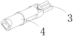
Fig. 1 is a top view of the structure of the present invention;
FIG. 2 is a schematic view of the connection structure between the plastic housing and the circuit board of the present invention;
fig. 3 is a schematic view of the metal terminal structure of the present invention;
fig. 4 is a schematic structural view of the front end of the plastic casing of the present invention;
fig. 5 is a schematic structural view of the rear end of the plastic shell of the present invention;
fig. 6 is a schematic diagram of the circuit board structure of the present invention;
FIG. 7 is a schematic view of the structure of the metal sheet of the present invention;
fig. 8 is a schematic view of the structure of the protective encapsulating layer of the present invention.
Reference numerals are as follows: 1. a plastic housing; 2. a metal terminal; 201. a contact piece; 202. a wire harness sheet; 3. a wire; 4. protecting the rubber coating layer; 5. a metal sheet; 6. clamping into an edge; 7. a clamping groove is formed; 8. a lead wire through hole; 9. An anti-drop block; 11. a clamping hole; 12. a circuit board; 13. an insertion head; 14. a card slot; 15. a clamping block; 16. A circuit board golden finger; 17. the anti-drop mouth.
Detailed Description
The technical solutions in the embodiments of the present invention will be described clearly and completely with reference to the accompanying drawings in the embodiments of the present invention, and it is obvious that the described embodiments are only some embodiments of the present invention, not all embodiments. Based on the embodiments in the present invention, all other embodiments obtained by a person skilled in the art without creative efforts all belong to the protection scope of the present invention.
Examples
Referring to fig. 1-8, a wire-to-plate converter includes a plastic housing 1 and a circuit board 12, a metal terminal 2 is installed inside the plastic housing 1, a metal sheet 5 is installed on the plastic housing 1, a fastening hole 11 is formed at one end of the metal sheet 5, and anti-falling blocks 9 are respectively arranged on two sides of the plastic housing 1;
clamping edges 6 are arranged on two sides of the metal sheet 5, and a clamping block 15 is fixedly arranged on one side of each clamping edge 6;
an insertion head 13 is arranged at one end of the circuit board 12, clamping grooves 14 are formed in two sides of the insertion head 13, and the clamping blocks 15 are connected inside the clamping grooves 14 in a clamping mode.
Through the technical scheme, the utility model discloses a be equipped with metal terminal 2, make circuit board 12 can insert the connection through insert head 13, the realization is to the transmission of signal, and be equipped with draw-in groove 14 in insert head 13's both sides, be equipped with fixture block 15 in the both sides of card income limit 6, settlement through fixture block 15 and draw-in groove 14, can make circuit board 12 when inserting the connection, can remain stable connectivity, prevent to drop, and be equipped with block hole 11 on sheetmetal 5, be equipped with anticreep piece 9 on plastic housing 1, can make plastic housing 1 and sheetmetal 5 when installing fixedly, keep stable, prevent to drop, and be convenient for install and the dismantlement combination.
In this embodiment, preferably, clamping grooves 7 are formed in two sides of one end of the plastic shell 1, the clamping edges 6 are connected in the clamping grooves 7 in a clamping manner, and the anti-falling block 9 is connected in the clamping holes 11 in a clamping manner. The effect is that the setting of the clamping groove 7 is convenient for the clamping edge 6 to clamp in, the metal sheet 5 is effectively fixed, and the setting of the clamping hole 11 is convenient for the anti-falling block 9 to clamp in, so that the stability of the metal sheet 5 is kept.
In this embodiment, it is preferable that a circuit board finger 16 is provided on a lower portion of the insertion head 13, and the metal terminal 2 is attached to a lower portion of the circuit board finger 16. The effect is that the setting of the circuit board golden finger 16 can be electrically connected with the metal terminal 2, and the data information can be transmitted.
In this embodiment, preferably, the protective rubber coating 4 is further included, the protective rubber coating 4 is arranged outside the plastic shell 1 and the metal sheet 5 in an injection molding manner, and the anti-return block 10 is embedded and mounted inside the protective rubber coating 4; the tail end of the protective rubber coating layer 4 is embedded with a lead 3; the metal sheet 5 is also embedded in the protective rubber coating layer 4, and the end part of the metal sheet 5 is provided with an anti-falling opening 17. The effect does, and protection rubber coating 4 is set for through moulding plastics, can effectual realization connect, realizes the wholeness, prevents that the structure from droing.
In this embodiment, it is preferable that the metal terminal 2 is provided with two sections, one section of the metal terminal 2 is a contact piece 201 for contacting the circuit board golden finger 16, and the other section of the metal terminal 2 is a wire harness piece 202 for connecting a cable. The metal terminal 2 is provided with two sections to facilitate electrical connection with the circuit board gold finger 16 and the cable, and the contact piece 201 has elasticity to improve contact connectivity with the circuit board gold finger 16.
In this embodiment, it is preferable that the lead wire 3 is located inside the plastic case 1 through the lead wire through hole 8, and the end of the lead wire 3 is stripped of insulation and then connected to the inside of the harness piece 202 in a clamped manner. The effect is that, the setting of wire 3 is used for realizing the transmission of power supply connection or signal, and the setting of bunch piece 202 can realize carrying out electric connection to the tip of skinning of wire 3, realizes effectual transmission data.
The use principle and the advantages are as follows:
when the anti-dropping device is used, the metal sheet 5 is connected to the plastic shell 1 in a clamping mode, the clamping edge 6 is connected to the inside of the clamping groove 7 in a clamping mode, then the circuit board 12 is connected to the inside of the plastic shell 1 in an inserting mode through the inserting head 13, the clamping grooves 14 on two sides of the inserting head 13 are connected to the clamping blocks 15 on the clamping edge 6 in a clamping mode, the circuit board 12 is prevented from dropping, then the wire 3 penetrates through the wire through hole 8, the peeling end portion of the wire 3 is electrically connected to the inside of the wire bundling sheet 202, the metal terminal 2 is connected with the circuit board golden finger 16 on the lower portion of the inserting head 13 in an attaching mode, then the plastic shell 1, the connector of the metal sheet 5 and the connector of the wire 3 are connected with the protective rubber coating layer 4 in an injection molding mode, the anti-dropping block 9 is connected to the inside of the clamping hole 11 of the metal sheet 5 in a clamping mode, and the anti-dropping block 10 and the anti-dropping port 17 are embedded to the inside of the protective rubber coating layer 4.
Although embodiments of the present invention have been shown and described, it will be appreciated by those skilled in the art that changes, modifications, substitutions and alterations can be made in these embodiments without departing from the principles and spirit of the invention, the scope of which is defined in the appended claims and their equivalents.
Claims (6)
1. A wire-to-board converter comprises a plastic shell (1) and a circuit board (12), and is characterized in that: a metal terminal (2) is installed inside the plastic shell (1), a metal sheet (5) is installed on the plastic shell (1), two clamping holes (11) are formed in one end of the metal sheet (5), and anti-falling blocks (9) are respectively arranged on two sides of the plastic shell (1);
clamping edges (6) are arranged on two sides of the metal sheet (5), and clamping blocks (15) are fixedly arranged on one sides of the clamping edges (6);
one end of the circuit board (12) is provided with an insertion head (13), clamping grooves (14) are formed in two sides of the insertion head (13), and the clamping blocks (15) are clamped and connected inside the clamping grooves (14).
2. A wire-to-board converter according to claim 1, wherein: the clamping groove (7) is formed in two sides of one end of the plastic shell (1), the clamping edges (6) are connected to the inside of the clamping groove (7) in a clamping mode, and the anti-falling block (9) is connected to the inside of the clamping hole (11) in a clamping mode.
3. A wire-to-board converter as defined in claim 1, wherein: the lower part of the insertion head (13) is provided with a circuit board golden finger (16), and the metal terminal (2) is attached and connected to the lower part of the circuit board golden finger (16).
4. A wire-to-board converter according to claim 1, wherein: the plastic casing is characterized by further comprising a protective rubber coating layer (4), wherein the protective rubber coating layer (4) is arranged outside the plastic casing (1) and the metal sheet (5) in an injection molding mode, and an anti-return block (10) is embedded in the protective rubber coating layer (4); the tail end of the protective rubber coating layer (4) is embedded with a lead (3); the metal sheet (5) is also embedded in the protective encapsulating layer (4), and the end part of the metal sheet (5) is provided with an anti-dropping opening (17).
5. The wire-to-board converter of claim 4, wherein: the metal terminal (2) is provided with two sections, one section of the metal terminal (2) is a contact piece (201) used for contacting the circuit board golden finger (16), and the other section of the metal terminal (2) is a wire harness piece (202) used for connecting a cable.
6. A wire-to-board converter according to claim 5, wherein: the wire (3) is arranged in the plastic shell (1) through the wire through hole (8), and the end of the wire (3) is stripped of insulation and then is clamped and connected in the wire bundling piece (202).
Priority Applications (1)
| Application Number | Priority Date | Filing Date | Title |
|---|---|---|---|
| CN202221975688.1U CN218770141U (en) | 2022-07-28 | 2022-07-28 | Wire-to-board converter |
Applications Claiming Priority (1)
| Application Number | Priority Date | Filing Date | Title |
|---|---|---|---|
| CN202221975688.1U CN218770141U (en) | 2022-07-28 | 2022-07-28 | Wire-to-board converter |
Publications (1)
| Publication Number | Publication Date |
|---|---|
| CN218770141U true CN218770141U (en) | 2023-03-28 |
Family
ID=85690205
Family Applications (1)
| Application Number | Title | Priority Date | Filing Date |
|---|---|---|---|
| CN202221975688.1U Active CN218770141U (en) | 2022-07-28 | 2022-07-28 | Wire-to-board converter |
Country Status (1)
| Country | Link |
|---|---|
| CN (1) | CN218770141U (en) |
-
2022
- 2022-07-28 CN CN202221975688.1U patent/CN218770141U/en active Active
Similar Documents
| Publication | Publication Date | Title |
|---|---|---|
| CN213692385U (en) | An automobile cable with quick wiring function | |
| CN207233995U (en) | A kind of buckle type electric connector | |
| CN213602036U (en) | Female terminal | |
| CN205264887U (en) | Clamshell FPC Connector | |
| CN218975860U (en) | Network module | |
| CN218525861U (en) | Adapter plug that PCB board switches on | |
| CN207625011U (en) | Socket connector | |
| CN211404879U (en) | Connector for electronic wire harness | |
| CN211265817U (en) | USB connecting wire is used for interface fixed establishment | |
| CN223156383U (en) | Main wire bundle plug-in structure of electric vehicle instrument | |
| CN215645276U (en) | Small-size equipment cable connection structure | |
| CN219696798U (en) | Anti-aging power line with stable plugging function | |
| CN216563679U (en) | Energy storage power connector | |
| CN216055300U (en) | Female seat of connector is with connecting terminal reinforced structure | |
| CN221201631U (en) | Photovoltaic energy storage high-voltage wire harness | |
| CN222380915U (en) | A connector housing | |
| CN212783990U (en) | Buckle type waterproof connector | |
| CN222581699U (en) | Charging socket capable of being assembled conveniently | |
| CN221201604U (en) | Cable conductor connecting pipe | |
| CN219203691U (en) | USB connector with controllable terminal spring height | |
| CN223309300U (en) | A waterproof and dustproof automotive electronic wiring harness | |
| CN210607938U (en) | Straight-head power line | |
| CN218648226U (en) | Self-locking type waterproof wiring connecting device | |
| CN213878631U (en) | Type-C exempts from PCB structure male connector | |
| CN220253587U (en) | Double FFC pencil connecting device and electronic product |
Legal Events
| Date | Code | Title | Description |
|---|---|---|---|
| GR01 | Patent grant | ||
| GR01 | Patent grant |