CN218766062U - Test piece cutting jig - Google Patents
Test piece cutting jig Download PDFInfo
- Publication number
- CN218766062U CN218766062U CN202222417981.2U CN202222417981U CN218766062U CN 218766062 U CN218766062 U CN 218766062U CN 202222417981 U CN202222417981 U CN 202222417981U CN 218766062 U CN218766062 U CN 218766062U
- Authority
- CN
- China
- Prior art keywords
- base
- clamping device
- rod
- connecting part
- clamping
- Prior art date
- Legal status (The legal status is an assumption and is not a legal conclusion. Google has not performed a legal analysis and makes no representation as to the accuracy of the status listed.)
- Active
Links
- 238000012360 testing method Methods 0.000 title claims abstract description 21
- 239000002184 metal Substances 0.000 claims abstract description 11
- 230000009286 beneficial effect Effects 0.000 abstract description 5
- 230000003028 elevating effect Effects 0.000 description 7
- 238000010586 diagram Methods 0.000 description 6
- 239000010426 asphalt Substances 0.000 description 3
- 238000005516 engineering process Methods 0.000 description 3
- 238000000034 method Methods 0.000 description 2
- 239000000203 mixture Substances 0.000 description 2
- 238000004519 manufacturing process Methods 0.000 description 1
- 238000005259 measurement Methods 0.000 description 1
Images



Landscapes
- Sampling And Sample Adjustment (AREA)
Abstract
本实用新型公开了一种试件切割夹具,包括底盘和夹持装置基座,所述底盘的内侧设置有辅助装置,且辅助装置包括活动架和工作台,所述活动架的上方设置有工作台,且工作台的内部前端开设有基座槽,且工作台的后侧上方设置有金属挡板,所述夹持装置基座设置于基座槽的上方前端,且夹持装置基座的上方设置有基座身,所述基座身的内部螺纹连接有基座固定螺丝。该试件切割夹具,通过底盘、活动架、工作台、夹持装置基座、顶部夹持装置和水平夹持装置,有利于对所切割试件进行多方面多角度的夹持,并且夹持装置基座可活动地设置于基座槽,以相对于锯片切割方向平行移动,金属挡板可根据切割锯片宽度等实际使用因素,设置不同位置、不同宽度的切割缝。

The utility model discloses a test piece cutting fixture, which comprises a chassis and a clamping device base. An auxiliary device is arranged on the inner side of the chassis, and the auxiliary device includes a movable frame and a workbench. platform, and the inner front end of the workbench is provided with a base groove, and a metal baffle is arranged above the rear side of the workbench, the base of the clamping device is arranged at the upper front end of the base groove, and the base of the clamping device A base body is arranged above, and the inner thread of the base body is connected with base fixing screws. The specimen cutting jig, through the chassis, movable frame, workbench, clamping device base, top clamping device and horizontal clamping device, is beneficial to clamp the cut specimen in various aspects and angles, and clamps The base of the device can be movably arranged in the base groove to move parallel to the cutting direction of the saw blade. The metal baffle can be set with different positions and different widths of cutting slits according to the actual use factors such as the width of the cutting saw blade.
Description
技术领域technical field
本实用新型涉及道路工程技术领域,具体为一种试件切割夹具。The utility model relates to the technical field of road engineering, in particular to a test piece cutting jig.
背景技术Background technique
近年来,随着道路工程技术以及沥青路面测试技术的快速发展,与沥青混合料试件及混凝土试件配套的实验仪器也越来越完善,然而市面上常见的沥青混合料试件小型切割机所使用的试件夹具存在泛用性低,夹持不稳定的问题。In recent years, with the rapid development of road engineering technology and asphalt pavement testing technology, the experimental instruments supporting asphalt mixture specimens and concrete specimens have become more and more perfect. However, the common small cutting machine for asphalt mixture specimens on the market The used specimen fixture has the problems of low versatility and unstable clamping.
现有公开号CN203853825U,名为“切割机定位夹具”的专利,该装置通过方形的切割平台,设有锯片的切割装置固定在切割平台的上方,所述切割平台进料侧滑动连接有两条平行于切割平台长度方向的限位板,所述限位板下方的切割平台上横向开设有与所述限位板配合滑动的滑槽,所述任意一条限位板的长度方向上等间隔固定有定位块,所述定位块通过合页固定在所述限位板上,本实用新型使用时将工件夹在两条限位板之间,限位板上设有定位块,其能够抵住工件的尾端,起到纵向定位的功能,合页的固定方式使其能够随意翻转,一次定位落下一个定位块即可,使用灵活方便,等间隔的排列能够保证每次切割的工件长度一致,不需要经过繁琐的重复测量,大大提高了日常生产的效率。The existing publication number CN203853825U is a patent named "Cutting Machine Positioning Fixture". The device passes through a square cutting platform, and the cutting device provided with saw blades is fixed on the top of the cutting platform. The strips are parallel to the limiting plate in the length direction of the cutting platform, and the cutting platform below the limiting plate is horizontally provided with a chute that cooperates with the limiting plate to slide, and the length direction of any one of the limiting plates is equally spaced A positioning block is fixed, and the positioning block is fixed on the limiting plate through a hinge. When the utility model is used, the workpiece is clamped between two limiting plates, and a positioning block is arranged on the limiting plate, which can resist It holds the tail end of the workpiece and plays the function of longitudinal positioning. The fixing method of the hinge enables it to be turned over at will, and one positioning block can be dropped at one time. It is flexible and convenient to use, and the arrangement at equal intervals can ensure that the length of the workpiece for each cutting is consistent. , without cumbersome repeated measurement, greatly improving the efficiency of daily production.
上述装置在使用过程中,将工件夹在两条限位板之间,限位板上设有定位块,其能够抵住工件的尾端,起到纵向定位的功能,但是无法对多种样式的工件进行稳定夹持,且不便多位置切割工件,为此,我们提出一种试件切割夹具。During the use of the above-mentioned device, the workpiece is clamped between two limit plates, and the limit plate is provided with a positioning block, which can resist the tail end of the workpiece and perform the function of longitudinal positioning, but it cannot be used for various styles. The workpiece is stably clamped, and it is inconvenient to cut the workpiece at multiple positions. Therefore, we propose a specimen cutting fixture.
实用新型内容Utility model content
本实用新型的目的在于提供一种试件切割夹具,以解决上述背景技术中提出的问题。The purpose of this utility model is to provide a test piece cutting jig to solve the problems raised in the above-mentioned background technology.
为实现上述目的,本实用新型提供如下技术方案:一种试件切割夹具,包括底盘和夹持装置基座,所述底盘的内侧设置有辅助装置,且辅助装置包括活动架和工作台,所述活动架的上方设置有工作台,且工作台的内部前端开设有基座槽,且工作台的上方后端设置有金属挡板,所述夹持装置基座设置于基座槽的上方前端,且夹持装置基座的上方设置有基座身,所述基座身的内部螺纹连接有基座固定螺丝。In order to achieve the above object, the utility model provides the following technical solutions: a test piece cutting fixture, including a chassis and a clamping device base, an auxiliary device is provided on the inner side of the chassis, and the auxiliary device includes a movable frame and a workbench. A workbench is provided above the movable frame, and a base groove is provided at the inner front end of the workbench, and a metal baffle is arranged at the upper rear end of the workbench, and the base of the clamping device is arranged at the upper front end of the base groove , and a base body is provided above the base of the clamping device, and a base fixing screw is threaded inside the base body.
进一步的,所述基座槽的上方设置有顶部夹持装置,且顶部夹持装置的上方安装有主杆一。Further, a top clamping device is provided above the base groove, and a
进一步的,所述主杆一的上方设置有连接部件一,且主杆一与连接部件一为卡合连接。Further, a connecting
进一步的,所述连接部件一的左右两侧均设置有连接部件固定螺丝,且连接部件一的内部设置有升降杆。Further, the left and right sides of the first connecting part are provided with fixing screws for the connecting part, and the inside of the first connecting part is provided with a lifting rod.
进一步的,所述升降杆的后端设置有连接部件二,且升降杆与连接部件二为螺纹连接。Further, the rear end of the lifting rod is provided with a connecting
进一步的,所述连接部件二的内部设置有夹持杆,且夹持杆的下方设置有轴承,所述轴承的下端设置有夹持块。Further, a clamping rod is provided inside the connecting
进一步的,所述基座槽的上方设置有水平夹持装置,且水平夹持装置包括主杆二和连接部件三,所述主杆二的外部上端设置有连接部件三。Further, a horizontal clamping device is provided above the base groove, and the horizontal clamping device includes a main rod two and a connecting part three, and the outer upper end of the main rod two is provided with a connecting part three.
本实用新型提供了一种试件切割夹具,具备以下有益效果:通过底盘、活动架、工作台、夹持装置基座、顶部夹持装置和水平夹持装置,有利于对所切割试件进行多方面多角度的夹持;The utility model provides a test piece cutting fixture, which has the following beneficial effects: through the chassis, the movable frame, the workbench, the base of the clamping device, the top clamping device and the horizontal clamping device, it is beneficial to carry out the cutting of the test piece. Multi-faceted and multi-angle clamping;
1、本实用新型通过底盘、活动架、工作台、夹持装置基座、顶部夹持装置和水平夹持装置的设置,将切割机及活动架通过螺丝设置于底盘,工作台可活动地设置于活动架,通过水平移动使得工作台所设置金属挡板上的切割缝与锯片位置相适应。夹持装置基座设置于工作台,用于粗略调整以及固定顶部夹持装置及水平夹持装置,顶部夹持装置及水平夹持装置根据实际需要,通过夹持装置基座连接于工作台,有利于对所切割试件进行多方面多角度的夹持。1. The utility model sets the cutting machine and the movable frame on the chassis through screws through the setting of the chassis, movable frame, workbench, clamping device base, top clamping device and horizontal clamping device, and the workbench can be set movably For the movable frame, the cutting seam on the metal baffle set on the workbench is adapted to the position of the saw blade through horizontal movement. The base of the clamping device is set on the workbench for rough adjustment and fixing of the top clamping device and the horizontal clamping device. The top clamping device and the horizontal clamping device are connected to the workbench through the clamping device base according to actual needs. It is beneficial to clamp the cut test piece in various aspects and angles.
附图说明Description of drawings
图1为本实用新型一种试件切割夹具装置的正视立体结构示意图;Fig. 1 is a front view three-dimensional structural schematic diagram of a test piece cutting fixture device of the present invention;
图2为本实用新型一种试件切割夹具装置的底盘与活动架立体结构示意图;Fig. 2 is a three-dimensional structural schematic diagram of a chassis and a movable frame of a test piece cutting fixture device of the present invention;
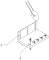
图3为本实用新型一种试件切割夹具装置的基座槽与金属挡板立体结构示意图;Fig. 3 is a three-dimensional structural schematic diagram of a base groove and a metal baffle of a test piece cutting fixture device of the present invention;
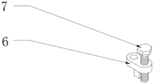
图4为本实用新型一种试件切割夹具装置的基座身与基座固定螺丝展开立体结构示意图。Fig. 4 is a three-dimensional structural schematic diagram of a base body and base fixing screws of a test piece cutting fixture device of the present invention.
图5为本实用新型一种试件切割夹具装置的顶部夹持装置的主杆一与夹持杆立体结构示意图;Fig. 5 is a schematic diagram of the three-dimensional structure of the main rod one and the clamping rod of the top clamping device of a test piece cutting fixture device of the present invention;
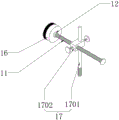
图6为本实用新型一种试件切割夹具装置的夹持块与水平夹持装置立体结构示意图。Fig. 6 is a three-dimensional structural schematic diagram of a clamping block and a horizontal clamping device of a specimen cutting fixture device of the present invention.
图中:1、底盘;2、辅助装置;201、活动架;202、工作台;3、基座槽;4、金属挡板;5、夹持装置基座;6、基座身;7、基座固定螺丝;8、顶部夹持装置;9、主杆一;10、升降杆;11、夹持杆;12、轴承;13、连接部件一;14、连接部件固定螺丝;15、连接部件二;16、夹持块;17、水平夹持装置;1701、主杆二;1702、连接部件三。In the figure: 1, chassis; 2, auxiliary device; 201, movable frame; 202, workbench; 3, base groove; 4, metal baffle; 5, clamping device base; 6, base body; 7, Base fixing screw; 8. Top clamping device; 9. Main rod one; 10. Lifting rod; 11. Clamping rod; 12. Bearing; 13. Connecting part one; 14. Connecting part fixing screw; 15. Connecting part Two; 16, clamping block; 17, horizontal clamping device; 1701, main rod two; 1702, connecting part three.
具体实施方式Detailed ways
如图1-3所示,一种试件切割夹具,包括底盘1和夹持装置基座5,底盘1的内侧设置有辅助装置2,且辅助装置2包括活动架201和工作台202,活动架201的上方设置有工作台202,且工作台202的内部前端开设有基座槽3,且工作台202的上方后端设置有金属挡板4,夹持装置基座5设置于基座槽3的上方前端,且夹持装置基座5的上方设置有基座身6,基座身6的内部螺纹连接有基座固定螺丝7,基座槽3的上方设置有顶部夹持装置8,且顶部夹持装置8的上方安装有主杆一9,将切割机及活动架201通过螺丝设置于底盘1,工作台202可活动地设置于活动架201,通过水平移动使得工作台202所设置金属挡板4上的切割缝与锯片位置相适应,夹持装置基座5设置于工作台202,用于粗略调整以及固定顶部夹持装置8及水平夹持装置17,顶部夹持装置8及水平夹持装置17根据实际需要,通过夹持装置基座5连接于工作台202,有利于对所切割试件进行多方面多角度的夹持,并且夹持装置基座5可活动地设置于基座槽3,以相对于锯片切割方向平行移动,金属挡板4可根据切割锯片宽度等实际使用因素,设置不同位置、不同宽度的切割缝,而基层固定螺丝7将基座身6固定于工作台202上,并通过主杆一9、主杆二1701低于基座身6的部分,保证基座身6不随着基座固定螺丝7的转动而转动。As shown in Figures 1-3, a specimen cutting jig includes a
如图1-6所示,主杆一9的上方设置有连接部件一13,且主杆一9与连接部件一13为卡合连接,连接部件一13的左右两侧均设置有连接部件固定螺丝14,且连接部件一13的内部设置有升降杆10,升降杆10的后端设置有连接部件二15,且升降杆10与连接部件二15为螺纹连接,连接部件二15的内部设置有夹持杆11,且夹持杆11的下方设置有轴承12,轴承12的下端设置有夹持块16,主杆一9下端通过夹持装置基座5与工作台202连接,主杆一9上端通过连接部件一13与升降杆10一端连接,通过调节主杆一9与升降杆10分别相较于连接部件一13的相对位置,控制升降杆10方向以及升降杆10与工作台202的相对高度,并通过连接部件固定螺丝14进行固定,升降杆10另一端通过连接部件二15与夹持杆11连接,通过旋动夹持杆11带动夹持块16向下移动夹持试件,并且夹持杆11旋转可带动轴承12的内圈,不影响轴承12外圈活动,夹持块16与轴承12外圈连接,也不影响轴承12内圈活动,因此,轴承12使得夹持杆11运动时,夹持块16只进行竖直方向的运动,不跟随夹持杆11旋转,同时通过连接部件固定螺丝14进行固定,而连接部件一13两个孔洞均为光滑,连接部件二15孔洞含有内螺纹,基座槽3的上方设置有水平夹持装置17,且水平夹持装置17包括主杆二1701和连接部件三1702,主杆二1701的外部上端设置有连接部件三1702,主杆二1701下端通过夹持装置基座5与工作台202连接,主杆二1701上端通过连接部件三1702与夹持杆11连接,通过调节主杆二1701与连接部件三1702相对位置,控制夹持杆11方向及夹持杆11与工作台202的相对高度,并通过连接部件固定螺丝14进行固定,通过旋动夹持杆11带动夹持块16水平移动夹持试件,并通过连接部件固定螺丝14进行固定,此外,连接部件三1702一个孔洞内壁光滑,另一孔洞含有内螺纹,夹持杆11旋转可带动轴承12的内圈,不影响轴承12外圈活动,夹持块16与轴承12外圈连接,不影响轴承12内圈活动,因此,轴承12使得夹持杆11运动时,夹持块16只进行水平方向的运动,不跟随夹持杆11旋转。As shown in Figure 1-6, a connecting
综上,该试件切割夹具,使用时,首先操作人员将切割机及活动架201通过螺丝设置于底盘1,工作台202可活动地设置于活动架201,通过水平移动使得工作台202所设置金属挡板4上的切割缝与锯片位置相适应,夹持装置基座5设置于工作台202,用于粗略调整以及固定顶部夹持装置8及水平夹持装置17,顶部夹持装置8及水平夹持装置17根据实际需要,主杆一9下端通过夹持装置基座5与工作台202连接,主杆一9上端通过连接部件一13与升降杆10一端连接,通过调节主杆一9与升降杆10分别相较于连接部件一13的相对位置,控制升降杆10方向以及升降杆10与工作台202的相对高度,并通过连接部件固定螺丝14进行固定,升降杆10另一端通过连接部件二15与夹持杆11连接,通过旋动夹持杆11带动夹持块16向下移动夹持试件,并通过连接部件固定螺丝14进行固定,主杆一9下端通过夹持装置基座5与工作台202连接,主杆一9上端通过连接部件一13与升降杆10一端连接,通过调节主杆一9与升降杆10分别相较于连接部件一13的相对位置,控制升降杆10方向以及升降杆10与工作台202的相对高度,并通过连接部件固定螺丝14进行固定,升降杆10另一端通过连接部件二15与夹持杆11连接,通过旋动夹持杆11带动夹持块16向下移动夹持试件,并通过连接部件固定螺丝14进行固定,此外,连接部件一13两个孔洞均为光滑,连接部件二15孔洞含有内螺纹,夹持杆11旋转可带动轴承12的内圈,不影响轴承12外圈活动,夹持块16与轴承12外圈连接,不影响轴承12内圈活动,因此,轴承12使得夹持杆11运动时,夹持块16只进行竖直方向的运动,不跟随夹持杆11旋转,连接部件三1702一个孔洞内壁光滑,另一孔洞含有内螺纹,夹持杆11旋转可带动轴承12的内圈,不影响轴承12外圈活动,夹持块16与轴承12外圈连接,不影响轴承12内圈活动,因此,轴承12使得夹持杆11运动时,夹持块16只进行水平方向的运动,不跟随夹持杆11旋转,这就是该试件切割夹具的工作原理。In summary, when using the specimen cutting jig, the operator first installs the cutting machine and the
Claims (7)
Priority Applications (1)
| Application Number | Priority Date | Filing Date | Title |
|---|---|---|---|
| CN202222417981.2U CN218766062U (en) | 2022-09-13 | 2022-09-13 | Test piece cutting jig |
Applications Claiming Priority (1)
| Application Number | Priority Date | Filing Date | Title |
|---|---|---|---|
| CN202222417981.2U CN218766062U (en) | 2022-09-13 | 2022-09-13 | Test piece cutting jig |
Publications (1)
| Publication Number | Publication Date |
|---|---|
| CN218766062U true CN218766062U (en) | 2023-03-28 |
Family
ID=85695365
Family Applications (1)
| Application Number | Title | Priority Date | Filing Date |
|---|---|---|---|
| CN202222417981.2U Active CN218766062U (en) | 2022-09-13 | 2022-09-13 | Test piece cutting jig |
Country Status (1)
| Country | Link |
|---|---|
| CN (1) | CN218766062U (en) |
-
2022
- 2022-09-13 CN CN202222417981.2U patent/CN218766062U/en active Active
Similar Documents
| Publication | Publication Date | Title |
|---|---|---|
| CN204913141U (en) | Axial fan impeller welding position device | |
| CN209319136U (en) | An adjustable jig for aluminum alloy welding | |
| CN208083887U (en) | Round piece quick clamping tool structure | |
| CN106944950B (en) | A kind of assembly fixture | |
| CN211539799U (en) | High-precision tapping machine | |
| CN222226555U (en) | A laser cladding machine for metallurgical surface repair | |
| CN222258692U (en) | BIM wheel mills mapping device | |
| CN222520352U (en) | Multidirectional welding jig | |
| CN219543113U (en) | Length measuring machine workbench | |
| CN209021754U (en) | A kind of profile milling device positioned using line laser marker | |
| CN211842178U (en) | A trimming and leveling device | |
| CN210046553U (en) | An adjustable woodworking quick clamp for quick clamping | |
| CN209050453U (en) | A kind of bench drill positioning device | |
| CN222037180U (en) | A manual laser cutting gun head chamfering tool | |
| CN222289863U (en) | Tool table with built-in bench vice tool box | |
| CN223933443U (en) | Tool for clamping angle workpiece | |
| CN219926286U (en) | A clamp for wood processing | |
| CN220806001U (en) | Adjustable clamp | |
| CN206084765U (en) | Positioner that polishes of laser cutting equipment | |
| CN222712097U (en) | A testing rack for parts | |
| CN224158060U (en) | A cutting machine for processing stainless steel | |
| CN224209184U (en) | Cutting device that steel construction processing was used | |
| CN223997064U (en) | Punching tool for machining power transmission tower components | |
| CN211589364U (en) | Numerical control equipment capable of automatically adjusting position of material | |
| CN219987303U (en) | Clamping device for punching |
Legal Events
| Date | Code | Title | Description |
|---|---|---|---|
| GR01 | Patent grant | ||
| GR01 | Patent grant |