CN218758727U - Post-cast strip construction structures - Google Patents
Post-cast strip construction structures Download PDFInfo
- Publication number
- CN218758727U CN218758727U CN202223164143.5U CN202223164143U CN218758727U CN 218758727 U CN218758727 U CN 218758727U CN 202223164143 U CN202223164143 U CN 202223164143U CN 218758727 U CN218758727 U CN 218758727U
- Authority
- CN
- China
- Prior art keywords
- post
- adjacent
- close
- center
- right sides
- Prior art date
- Legal status (The legal status is an assumption and is not a legal conclusion. Google has not performed a legal analysis and makes no representation as to the accuracy of the status listed.)
- Expired - Fee Related
Links
Images



Landscapes
- On-Site Construction Work That Accompanies The Preparation And Application Of Concrete (AREA)
Abstract
本实用新型公开了一种后浇带施工结构,包括支架,所述支架内腔左右两侧靠近中心处均开设有固定槽,两个所述固定槽左右两侧内壁靠近底部中心处均共同固定连接有工形板,本实用新型通过固定杆、固定筒、螺纹杆、握柄、滑杆以及滑板各部件之间的相互配合使用,使得该后浇带施工结构,通过便捷带动两个螺纹杆正向或者反向转动,使得两个螺纹杆能够同步的向着相邻的固定筒内腔移动或者移出,从而能够便捷的对两个固定筒之间的间距进行调整,便于两个固定筒共同带动后浇带向内收缩或者向外延伸对后浇带的尺寸进行调节,使得后浇带的长度能够与不同长度的施工缝相匹配进行连接工作,提高了该结构的实用性。

The utility model discloses a post-casting belt construction structure, which comprises a bracket, and the left and right sides of the inner cavity of the bracket are provided with fixing grooves close to the center, and the inner walls of the left and right sides of the two fixing grooves are fixed together near the center of the bottom The utility model is connected with an I-shaped plate. The utility model uses the mutual cooperation between the fixed rod, the fixed cylinder, the threaded rod, the handle, the sliding rod and the sliding plate, so that the construction structure of the post-casting belt can drive the two threaded rods conveniently. Rotate in the forward or reverse direction, so that the two threaded rods can move synchronously toward or out of the inner cavity of the adjacent fixed cylinder, so that the distance between the two fixed cylinders can be adjusted conveniently, so that the two fixed cylinders can drive together The inward shrinkage or outward extension of the post-casting tape adjusts the size of the post-casting tape, so that the length of the post-casting tape can be matched with construction joints of different lengths for connection work, which improves the practicability of the structure.
Description
技术领域technical field
本实用新型涉及建筑施工技术领域,尤其涉及一种后浇带施工结构。The utility model relates to the technical field of building construction, in particular to a post-pouring belt construction structure.
背景技术Background technique
在建筑混凝土结构的施工中,防止现浇钢筋混凝土结构由于自身收缩不均或沉降不均可能产生的有害裂缝,按照设计要求,在基础底板、墙、梁及上部楼板等相应位置留设临时施工缝,将结构暂时划分为若干部分,经过构件内部收缩,在若干时间后再浇筑该施工缝混凝土,将结构连成整体的地带即为后浇带。In the construction of building concrete structures, to prevent harmful cracks that may occur in the cast-in-place reinforced concrete structures due to uneven shrinkage or uneven settlement, according to the design requirements, temporary construction shall be reserved at the corresponding positions of the foundation floor, walls, beams and upper floors. The structure is divided into several parts temporarily, and the construction joint concrete is poured after a certain period of time after the internal contraction of the components, and the area that connects the structure into a whole is the post-casting belt.
目前,市场上使用到的后浇带施工结构,不能够快捷将支架从先浇筑混凝土带上取下,且不后浇带长度固定,造成现有的后浇带不能够适用到不同尺寸的施工缝,实用性较差,因此,针对上述问题提出了一种后浇带施工结构。At present, the post-cast belt construction structure used in the market cannot quickly remove the support from the pre-cast concrete belt, and the length of the post-cast belt is not fixed, so the existing post-cast belt cannot be applied to different sizes of construction Seams are poor in practicability. Therefore, a post-casting belt construction structure is proposed to solve the above problems.
实用新型内容Utility model content
为了克服现有技术的不足,本实用新型的目的之一在于提供一种后浇带施工结构。In order to overcome the deficiencies of the prior art, one of the purposes of the present utility model is to provide a post-cast belt construction structure.
本实用新型的目的之一采用如下技术方案实现:One of purpose of the utility model adopts following technical scheme to realize:
一种后浇带施工结构,包括支架,所述支架内腔左右两侧靠近中心处均开设有固定槽,两个所述固定槽左右两侧内壁靠近底部中心处均共同固定连接有工形板,两个所述工形板前后两侧内壁靠近左右两侧中心处均共同活动连接有转轴,位于左右两侧的两个所述转轴上靠近中心处均固定连接有卡杆,且位于左右两侧的两个所述卡杆上下两侧均贯穿相邻的固定槽内腔,所述支架顶部靠近左右两侧中心处均设有先浇筑混凝土带,且两个所述先浇筑混凝土带相邻的一侧共同设有后浇带,所述后浇带顶部靠近左右两侧中心处均设有固定筒,且两个所述固定筒内腔靠近相邻的一端中心处均设有螺纹杆,且两个所述螺纹杆螺纹攻丝朝向相反,两个所述固定筒相邻的一端靠近中心处均开设有通孔,且两个所述通孔内壁均开设有与相邻的螺纹杆相匹配的内螺纹,两个所述螺纹杆相邻的一端均贯穿相邻的通孔内腔,并共同固定连接有握柄。A post-cast belt construction structure, including a bracket, the left and right sides of the inner cavity of the bracket are provided with fixing grooves close to the center, and the inner walls of the left and right sides of the two fixing grooves are fixedly connected with I-shaped plates near the center of the bottom The inner walls of the front and rear sides of the two I-shaped plates are movably connected with rotating shafts near the centers of the left and right sides, and the two rotating shafts on the left and right sides are fixedly connected with clamping rods near the center, and are located on the left and right sides. The upper and lower sides of the two clamping rods on the side all pass through the inner cavity of the adjacent fixing groove, and the top of the support is near the center of the left and right sides. There are pre-poured concrete belts, and the two said first-poured concrete belts are adjacent to each other. One side of the post-casting belt is provided with a post-casting belt, and the top of the post-casting belt is provided with a fixed cylinder near the center of the left and right sides, and the inner cavity of the two fixed cylinders is provided with a threaded rod near the center of the adjacent end. In addition, the two threaded rods are directed in the opposite direction, and the adjacent ends of the two fixed cylinders are provided with through holes near the center, and the inner walls of the two through holes are provided with holes corresponding to the adjacent threaded rods. Matching internal threads, the adjacent ends of the two threaded rods pass through the inner cavity of the adjacent through hole, and are fixedly connected with the handle together.
进一步的,所述支架底部左右两侧中心处均固定连接有支腿,且两个所述支腿以支架内腔中心为对称轴呈左右对称设置。Further, outriggers are fixedly connected to the centers of the left and right sides of the bottom of the stent, and the two outriggers are symmetrically arranged with the center of the inner cavity of the stent as the axis of symmetry.
进一步的,两个所述先浇筑混凝土带以支架内腔中心为对称轴呈左右对称设置,且两个所述先浇筑混凝土带内腔开靠近相邻的一侧底部中心处均开设有预留卡槽。Further, the two pre-cast concrete belts are symmetrically arranged with the center of the inner cavity of the bracket as the axis of symmetry, and the inner cavities of the two first-cast concrete belts are opened near the center of the bottom of the adjacent side. card slot.
进一步的,两个所述固定筒底部远离后浇带内腔中心一端靠近中心处均活动连接有固定杆,且两个所述固定杆侧壁靠近底端处均设置成螺纹状,所述后浇带顶部靠近左右两侧中心处均开设有安装螺孔。Further, the bottoms of the two fixed cylinders are movably connected with fixed rods near the center of the inner cavity center of the post-cast tape, and the side walls of the two fixed rods are arranged in a threaded shape near the bottom ends, and the rear Mounting screw holes are provided near the center of the left and right sides on the top of the casting tape.
进一步的,位于左右两侧的两个所述卡杆相邻的一侧靠近底部处均设有复位弹簧,且两个所述复位弹簧左右两端均与相邻的卡杆靠近相邻的工形板内腔中心一侧靠近底部中心处固定连接。Further, the adjacent sides of the two clamping rods on the left and right sides are provided with return springs near the bottom, and the left and right ends of the two return springs are adjacent to the adjacent clamping rods. One side of the center of the inner cavity of the shaped plate is fixedly connected near the center of the bottom.
进一步的,两个所述固定筒左右两端内壁靠近上下两侧中心均共同固定连接有滑杆,位于左右两侧的两个所述滑杆上靠近中心处均套设有滑板,且两个所述滑板相邻的一侧靠近中心处均与相邻的螺纹杆远离握柄内腔中心一端固定连接。Further, the inner walls of the left and right ends of the two fixed cylinders are fixedly connected with slide bars near the centers of the upper and lower sides, and the two slide bars on the left and right sides are provided with slide plates near the center, and the two The adjacent side of the slide plate near the center is fixedly connected with the end of the adjacent threaded rod away from the center of the inner cavity of the handle.
进一步的,两个所述滑板内腔靠近上下两侧中心处均开设有滑孔,且两个所述滑板均通过相邻的两个滑孔与相邻的两个滑杆之间活动连接。Further, the inner cavities of the two slide plates are provided with slide holes near the centers of the upper and lower sides, and the two slide plates are movably connected to the two adjacent slide bars through the two adjacent slide holes.
相比现有技术,本实用新型的有益效果在于:Compared with the prior art, the beneficial effects of the utility model are:
1、本实用新型通过复位弹簧、工形板、卡杆以及转轴各部件之间的相互配合使用,使得该后浇带施工结构,通过两个复位弹簧的弹性作用能够便捷带动左右两侧的两个卡杆靠近底部处相靠拢,且左右两侧的两个卡杆靠近顶部处能够快捷的进行展开与相邻的预留卡槽相接触,从而能够便捷的将两个先浇筑混凝土带与支架连接在一起进行使用,同时也能够便捷将支架从两个先浇筑混凝土带上拆卸下来,提高了该结构的便捷性;1. The utility model uses the mutual cooperation between the return spring, the I-shaped plate, the clamping rod and the rotating shaft, so that the post-cast belt construction structure can conveniently drive the two sides on the left and right sides through the elastic action of the two return springs. The two clamping rods are close to the bottom, and the two clamping rods on the left and right sides can be quickly expanded and contacted with the adjacent reserved slots near the top, so that the two pre-poured concrete belts can be conveniently connected to the bracket. Connect together for use, and at the same time, the bracket can be easily disassembled from the two pre-cast concrete belts, which improves the convenience of the structure;
2、本实用新型通过固定杆、固定筒、螺纹杆、握柄、滑杆以及滑板各部件之间的相互配合使用,使得该后浇带施工结构,通过便捷带动两个螺纹杆正向或者反向转动,使得两个螺纹杆能够同步的向着相邻的固定筒内腔移动或者移出,从而能够便捷的对两个固定筒之间的间距进行调整,便于两个固定筒共同带动后浇带向内收缩或者向外延伸对后浇带的尺寸进行调节,使得后浇带的长度能够与不同长度的施工缝相匹配进行连接工作,提高了该结构的实用性。2. The utility model uses the mutual cooperation between the fixed rod, the fixed cylinder, the threaded rod, the handle, the sliding rod and the sliding plate, so that the construction structure of the post-cast belt can drive the two threaded rods forward or reverse through convenience. To rotate, so that the two threaded rods can move synchronously toward or out of the inner cavity of the adjacent fixed cylinder, so that the distance between the two fixed cylinders can be adjusted conveniently, so that the two fixed cylinders can jointly drive the post-casting belt to the The size of the post-cast belt can be adjusted by shrinking inward or extending outward, so that the length of the post-cast belt can be matched with construction joints of different lengths for connection work, which improves the practicability of the structure.
上述说明仅是本实用新型技术方案的概述,为了能够更清楚了解本实用新型的技术手段,而可依照说明书的内容予以实施,并且为了让本实用新型的上述和其他目的、特征和优点能够更明显易懂,以下特举较佳实施例,并配合附图,详细说明如下。The above description is only an overview of the technical solutions of the present utility model. In order to better understand the technical means of the present utility model, it can be implemented according to the contents of the description, and in order to make the above-mentioned and other purposes, features and advantages of the present utility model better It is obvious and easy to understand. The preferred embodiments are specifically cited below, together with the accompanying drawings, and detailed descriptions are as follows.
附图说明Description of drawings
图1为本实施例的主视结构示意图;Fig. 1 is the front view structure schematic diagram of present embodiment;
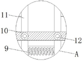
图2为本实施例的A处放大结构示意图;Fig. 2 is the schematic diagram of enlarged structure at A place of the present embodiment;
图3为本实施例的B处放大结构示意图;Fig. 3 is the schematic diagram of enlarged structure at B place of the present embodiment;
图4为本实施例的部件左侧工形板局部俯视结构示意图;Fig. 4 is a schematic structural diagram of a partial top view of the I-shaped plate on the left side of the component in this embodiment;
图5为本实施例的部件左侧固定筒局部右视结构示意图。Fig. 5 is a partial right view structural diagram of the left fixing cylinder of the present embodiment.
图中:1、支架;2、后浇带;3、支腿;4、先浇筑混凝土带;5、固定杆;6、固定筒;7、螺纹杆;8、握柄;9、复位弹簧;10、工形板;11、卡杆;12、转轴;13、滑杆;14、滑板。In the figure: 1. Bracket; 2. Post-pouring belt; 3. Outrigger; 4. First pouring concrete belt; 5. Fixing rod; 6. Fixing cylinder; 7. Threaded rod; 8. Handle; 10. I-shaped plate; 11. clamping rod; 12. rotating shaft; 13. sliding rod; 14. sliding plate.
具体实施方式Detailed ways
下面,结合附图以及具体实施方式,对本实用新型做进一步描述,需要说明的是,在不相冲突的前提下,以下描述的各实施例之间或各技术特征之间可以任意组合形成新的实施例。Below, the utility model will be further described in conjunction with the accompanying drawings and specific implementation methods. It should be noted that, on the premise of not conflicting, the various embodiments or technical features described below can be combined arbitrarily to form new implementations. example.
需要说明的是,当组件被称为“固定于”另一个组件,它可以直接在另一个组件上或者也可以存在居中的组件。当一个组件被认为是“连接”另一个组件,它可以是直接连接到另一个组件或者可能同时存在居中组件。当一个组件被认为是“设置于”另一个组件,它可以是直接设置在另一个组件上或者可能同时存在居中组件。本文所使用的术语“垂直的”、“水平的”、“左”、“右”以及类似的表述只是为了说明的目的。It should be noted that when a component is said to be "fixed" to another component, it can be directly on the other component or there can also be an intervening component. When a component is said to be "connected" to another component, it may be directly connected to the other component or there may be intervening components at the same time. When a component is said to be "set on" another component, it may be set directly on the other component or there may be an intervening component at the same time. The terms "vertical," "horizontal," "left," "right," and similar expressions are used herein for purposes of illustration only.
除非另有定义,本文所使用的所有的技术和科学术语与属于本实用新型的技术领域的技术人员通常理解的含义相同。本文中在本实用新型的说明书中所使用的术语只是为了描述具体的实施例的目的,不是旨在于限制本实用新型。本文所使用的术语“及/或”包括一个或多个相关的所列项目的任意的和所有的组合。Unless otherwise defined, all technical and scientific terms used herein have the same meaning as commonly understood by one of ordinary skill in the technical field of this invention. The terminology used in the description of the utility model herein is only for the purpose of describing specific embodiments, and is not intended to limit the utility model. As used herein, the term "and/or" includes any and all combinations of one or more of the associated listed items.
请参阅图1至图5,本实用新型提供一种技术方案:Please refer to Figure 1 to Figure 5, the utility model provides a technical solution:
实施例1:一种后浇带施工结构,包括支架1,支架1底部左右两侧中心处均固定连接有支腿3,且两个支腿3以支架1内腔中心为对称轴呈左右对称设置,支架1内腔左右两侧靠近中心处均开设有固定槽,两个固定槽左右两侧内壁靠近底部中心处均共同固定连接有工形板10,两个工形板10前后两侧内壁靠近左右两侧中心处均共同活动连接有转轴12,位于左右两侧的两个转轴12上靠近中心处均固定连接有卡杆11,且位于左右两侧的两个卡杆11上下两侧均贯穿相邻的固定槽内腔,支架1顶部靠近左右两侧中心处均设有先浇筑混凝土带4,两个先浇筑混凝土带4以支架1内腔中心为对称轴呈左右对称设置,且两个先浇筑混凝土带4内腔开靠近相邻的一侧底部中心处均开设有预留卡槽,且两个先浇筑混凝土带4相邻的一侧共同设有后浇带2,后浇带2顶部靠近左右两侧中心处均设有固定筒6,两个固定筒6底部远离后浇带2内腔中心一端靠近中心处均活动连接有固定杆5,且两个固定杆5侧壁靠近底端处均设置成螺纹状,后浇带2顶部靠近左右两侧中心处均开设有安装螺孔,且两个固定筒6内腔靠近相邻的一端中心处均设有螺纹杆7,且两个螺纹杆7螺纹攻丝朝向相反,两个固定筒6相邻的一端靠近中心处均开设有通孔,且两个通孔内壁均开设有与相邻的螺纹杆7相匹配的内螺纹,两个螺纹杆7相邻的一端均贯穿相邻的通孔内腔,并共同固定连接有握柄8;Embodiment 1: A post-casting belt construction structure, including a support 1, with
实施例2:位于左右两侧的两个卡杆11相邻的一侧靠近底部处均设有复位弹簧9,且两个复位弹簧9左右两端均与相邻的卡杆11靠近相邻的工形板10内腔中心一侧靠近底部中心处固定连接,便捷快捷的带动左右两侧的两个11靠近底部处相靠拢顶部处进行展开;Embodiment 2: the adjacent sides of the two clamping
实施例3:两个固定筒6左右两端内壁靠近上下两侧中心均共同固定连接有滑杆13,位于左右两侧的两个滑杆13上靠近中心处均套设有滑板14,两个滑板14内腔靠近上下两侧中心处均开设有滑孔,且两个滑板14均通过相邻的两个滑孔与相邻的两个滑杆13之间活动连接,且两个滑板14相邻的一侧靠近中心处均与相邻的螺纹杆7远离握柄8内腔中心一端固定连接,能够对两个螺纹杆7的位置进行限定,使得两个螺纹杆7能够平稳的向着相邻的固定筒6内腔移入或移出。Embodiment 3: The inner walls of the left and right ends of the two fixed
工作原理:使用时,工作人员依次向两侧拉动左右两侧的两个卡杆11,并将两个先浇筑混凝土带4通过预留卡槽套在左右两侧的两个卡杆11上,并使得两个先浇筑混凝土带4底部与支架1顶部靠近中心处相接触,然后工作人员停止拉动左右两侧的两个卡杆11,此时两个复位弹簧9在外力消失的情况下开始向内收缩,从而能够带动左右两侧的两个卡杆11靠近底部处相靠拢,此时左右两侧的两个卡杆11靠近顶部处在两个复位弹簧9的弹性作用下开始展开与相邻的预留卡槽相接触,从而能够将两个先浇筑混凝土带4固定在支架1上进行连接工作,当要将支架1从两个先浇筑混凝土带4上拆卸下来时,工作人员只需要再次向两侧拉动两个卡杆11即可,从而使得该后浇带施工结构,通过两个复位弹簧9的弹性作用能够便捷带动左右两侧的两个卡杆11靠近底部处相靠拢,且左右两侧的两个卡杆11靠近顶部处能够快捷的进行展开与相邻的预留卡槽相接触,从而能够便捷的将两个先浇筑混凝土带4与支架1连接在一起进行使用,同时也能够便捷将支架1从两个先浇筑混凝土带4上拆卸下来,提高了该结构的便捷性,接着工作人员依次正向转动两个固定杆5将两个固定杆5固定在相邻的安装孔内腔,接着工作人员正向或者反向转动握柄8,使得握柄8能够带动两个螺纹杆7正向或者反向转,由于两个螺纹杆7螺纹攻丝朝向相反,使得两个螺纹杆7能够同步的向着相邻的固定筒6内腔移动或者移出,两个螺纹杆7移动的过程中均带动相邻的滑板14在相邻的滑杆13上进行滑动,从而能够对两个螺纹杆7的位置进行限定,使得两个螺纹杆7能够平稳的进行移动,对两个固定筒6之间的间距进行调节,使得两个固定筒6能够带动后浇带2向内收缩或者向外延伸对后浇带2的尺寸进行调节,使得后浇带2的长度能够与不同长度的施工缝相匹配进行连接工作,从而使得该后浇带施工结构,通过便捷带动两个螺纹杆7正向或者反向转动,使得两个螺纹杆7能够同步的向着相邻的固定筒6内腔移动或者移出,从而能够便捷的对两个固定筒6之间的间距进行调整,便于两个固定筒6共同带动后浇带2向内收缩或者向外延伸对后浇带2的尺寸进行调节,使得后浇带2的长度能够与不同长度的施工缝相匹配进行连接工作,提高了该结构的实用性,接着工作人员将两个固定杆5从两个安装孔内腔转出,再向后浇带2上浇筑混凝土将两个先浇筑混凝土带4连接成整体,以上就是本实用新型的全部工作过程。Working principle: When in use, the staff pulls the two clamping
上述实施方式仅为本实用新型的优选实施方式,不能以此来限定本实用新型保护的范围,本领域的技术人员在本实用新型的基础上所做的任何非实质性的变化及替换均属于本实用新型所要求保护的范围。The above-mentioned embodiments are only preferred embodiments of the present utility model, and cannot be used to limit the scope of protection of the present utility model. The scope of protection required by the utility model.
Claims (7)
Priority Applications (1)
| Application Number | Priority Date | Filing Date | Title |
|---|---|---|---|
| CN202223164143.5U CN218758727U (en) | 2022-11-29 | 2022-11-29 | Post-cast strip construction structures |
Applications Claiming Priority (1)
| Application Number | Priority Date | Filing Date | Title |
|---|---|---|---|
| CN202223164143.5U CN218758727U (en) | 2022-11-29 | 2022-11-29 | Post-cast strip construction structures |
Publications (1)
| Publication Number | Publication Date |
|---|---|
| CN218758727U true CN218758727U (en) | 2023-03-28 |
Family
ID=85675056
Family Applications (1)
| Application Number | Title | Priority Date | Filing Date |
|---|---|---|---|
| CN202223164143.5U Expired - Fee Related CN218758727U (en) | 2022-11-29 | 2022-11-29 | Post-cast strip construction structures |
Country Status (1)
| Country | Link |
|---|---|
| CN (1) | CN218758727U (en) |
-
2022
- 2022-11-29 CN CN202223164143.5U patent/CN218758727U/en not_active Expired - Fee Related
Similar Documents
| Publication | Publication Date | Title |
|---|---|---|
| CN206376529U (en) | A kind of building template back cord component | |
| CN115233819B (en) | Assembled lacing wire steel pipe concrete connection structure | |
| CN207348095U (en) | The special bearing diagonal component of piping lane | |
| CN111173269A (en) | An adjustable internal formwork structure for elevator shafts | |
| CN108240110A (en) | Outrigger shear wall reserved opening forming composition template, shear wall, reserved opening sprue and its method | |
| CN110512766A (en) | A kind of the fabricated construction system and its construction method of steel plate concrete shear wall | |
| CN221878811U (en) | Pouring template assembly | |
| CN209556429U (en) | Building modeling supporting construction | |
| CN111851993A (en) | A double-sided formwork for deformation joint and construction method thereof | |
| CN104533078B (en) | Mark time tooth raft formula from fissure of displacement template system | |
| CN216377194U (en) | Assembled is externally-hung wallboard overhead hoist for building | |
| CN210507150U (en) | But segmental beam pier kicking block notch template of whole dismouting | |
| CN216516853U (en) | Cast-in-place structure reserves tenon fourth of twelve earthly branches and decorates roof beam construction equipment | |
| CN212105128U (en) | Splicing support structure of aluminum formwork for building | |
| CN212957617U (en) | Ratchet type template sliding device | |
| CN204531361U (en) | Guarantee the removable triangular support bracket of horizontal support | |
| CN211257274U (en) | Assembly type underground structure accessory | |
| CN114961017A (en) | Prefabricated component for assembly type green building | |
| CN218117201U (en) | Combined assembled waterproof building template | |
| CN209083004U (en) | A kind of civil chain architecture structure | |
| CN220666906U (en) | Self-adaptive telescopic template | |
| CN222140710U (en) | Building concrete template bearing structure | |
| CN216341047U (en) | Precast concrete prefabricated plate assembling device for building engineering | |
| CN221736515U (en) | A concrete shear wall mold | |
| CN224106868U (en) | Quick-release temporary support device for large-span composite floor slabs |
Legal Events
| Date | Code | Title | Description |
|---|---|---|---|
| GR01 | Patent grant | ||
| GR01 | Patent grant | ||
| CF01 | Termination of patent right due to non-payment of annual fee | ||
| CF01 | Termination of patent right due to non-payment of annual fee |
Granted publication date: 20230328 |