CN218754486U - Net frame component carrying and auxiliary assembling device - Google Patents
Net frame component carrying and auxiliary assembling device Download PDFInfo
- Publication number
- CN218754486U CN218754486U CN202223174663.4U CN202223174663U CN218754486U CN 218754486 U CN218754486 U CN 218754486U CN 202223174663 U CN202223174663 U CN 202223174663U CN 218754486 U CN218754486 U CN 218754486U
- Authority
- CN
- China
- Prior art keywords
- rod
- frame
- horizontal frame
- net frame
- supporting
- Prior art date
- Legal status (The legal status is an assumption and is not a legal conclusion. Google has not performed a legal analysis and makes no representation as to the accuracy of the status listed.)
- Active
Links
- 238000010276 construction Methods 0.000 abstract description 6
- 238000000034 method Methods 0.000 abstract description 6
- 230000003028 elevating effect Effects 0.000 abstract 2
- 230000009286 beneficial effect Effects 0.000 abstract 1
- 229910000831 Steel Inorganic materials 0.000 description 12
- 239000010959 steel Substances 0.000 description 12
- 239000000725 suspension Substances 0.000 description 3
- 238000003466 welding Methods 0.000 description 3
- 210000001503 joint Anatomy 0.000 description 2
- 230000008092 positive effect Effects 0.000 description 2
- TVEXGJYMHHTVKP-UHFFFAOYSA-N 6-oxabicyclo[3.2.1]oct-3-en-7-one Chemical compound C1C2C(=O)OC1C=CC2 TVEXGJYMHHTVKP-UHFFFAOYSA-N 0.000 description 1
- 230000000903 blocking effect Effects 0.000 description 1
- 239000000463 material Substances 0.000 description 1
- 230000003014 reinforcing effect Effects 0.000 description 1
Images


Landscapes
- Handcart (AREA)
Abstract
The utility model provides a net frame structure spare transport and supplementary assembly device, including braced frame, elevating gear and removal subassembly, the braced frame both ends are equipped with elevating gear for hoist and mount net frame spare, it is in to remove the subassembly setting braced frame bottom is used for removing braced frame. The beneficial effects of the utility model are that reduced the construction cost in net frame structure spare transport and the equipment process, reduced the potential safety hazard, simple structure, the simple operation has realized the high-efficient transport and the equipment of net frame structure spare, has improved work efficiency.
Description
Technical Field
The utility model belongs to the technical field of the construction, especially, relate to a net frame structure spare transport and supplementary assembly device.
Background
The net frame member is a part for building a net frame structure, the weight of hollow spheres, hollow sphere rod pieces and part of bolt spheres and bolt sphere rod pieces in the net frame member is (100-500) kg, and the net frame member cannot be carried by constructors. At least two truck cranes are required to be occupied in the transportation process, and the transportation cost is high. During assembly, the net frame members need to be hoisted by a truck for auxiliary butt assembly or welding, and the assembly efficiency is low. The use cost of the truck crane is high, and potential safety hazards exist in the use process.
SUMMERY OF THE UTILITY MODEL
In order to solve the technical problem, the utility model provides a net frame structure spare transport and supplementary assembly device, the effectual problem that has solved that construction cost is higher and have the potential safety hazard in net frame structure spare transport and the assembling process has overcome the not enough of prior art.
The utility model adopts the technical proposal that: a net frame member handling and auxiliary assembling device comprises:
the two ends of the supporting frame are provided with lifting devices for hoisting the net frame members;
and the moving assembly is arranged at the bottom of the supporting frame and used for moving the supporting frame.
Further, braced frame includes horizontal frame, pole setting and down tube, the pole setting symmetry sets up the horizontal frame both sides, the pole setting top with horizontal frame connects, the pole setting bottom with it connects to remove the subassembly, the horizontal frame both ends are equipped with the down tube, down tube one end with horizontal frame connects, the other end with it connects to remove the subassembly.
Further, horizontal frame includes mobile jib and horizontal pole, mobile jib parallel arrangement, be equipped with between the mobile jib the horizontal pole.
Furthermore, one end of the horizontal frame is provided with a draw bar, and the draw bar is arranged between the main rods.
Furthermore, both ends of the traction rod are provided with supporting rods, and one end of each supporting rod is rotatably connected with the traction rod.
Furthermore, a limiting block is arranged at one end, close to the branch rod, of the main rod and used for fixing the branch rod.
Furthermore, one end of the horizontal frame, which is far away from the traction rod, is provided with a handrail.
Furthermore, supports are arranged on the upper portions of the two ends of the supporting frame, and the lifting device is arranged on the upper portions of the supports.
Further, the moving assembly comprises rollers, and the rollers are symmetrically arranged on two sides of the supporting frame.
The utility model has the advantages and positive effects that: by adopting the technical scheme, the construction cost in the process of carrying and assembling the net frame members is reduced, the potential safety hazard is reduced, the structure is simple, the operation is convenient, the efficient carrying and assembling of the net frame members are realized, and the working efficiency is improved.
Drawings
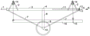
Fig. 1 is a front view of a net frame structure carrying and auxiliary assembling device according to an embodiment of the present invention with support rods retracted.
Fig. 2 is a top view of the net frame structure carrying and auxiliary assembling device according to the embodiment of the present invention.
Fig. 3 is a right side view of the net frame structure carrying and auxiliary assembling device according to the embodiment of the present invention with the supporting rods retracted.
Fig. 4 is a front view of the net frame structure in an embodiment of the present invention, with the supporting rod of the auxiliary assembling device being placed.
Fig. 5 is a top view of the net frame assembly carrying and auxiliary assembling device with its support rods lowered according to an embodiment of the present invention.
Fig. 6 is a right side view of the net frame assembly carrying and auxiliary assembling device according to the embodiment of the present invention with the supporting rod put down.
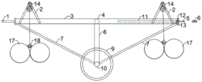
Fig. 7 is a schematic view illustrating a transportation of the net frame structure and the auxiliary assembling device according to an embodiment of the present invention.
Fig. 8 is a schematic view illustrating a transportation of the net frame structure and the auxiliary assembling device according to an embodiment of the present invention.
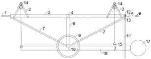
Fig. 9 is a schematic view illustrating an auxiliary assembly of the device for transporting and assembling net frame members according to an embodiment of the present invention.
In the figure:
1. arm rest 2, support 3 and main rod
4. Cross bar 5, trailer fastener (male) 6, trailer fastener (female)
7. Diagonal rod 8, upright rod 9 and roller
10. Fixed shaft 11, supporting rod 12 and traction rod
13. Limiting block 14, chain block 15 and hoisting sling
16. Rod member 17, hollow ball or bolt ball 18 and suspension buckle
Detailed Description
The embodiment of the utility model provides a net frame structure spare transport and supplementary assembly device, it is right to combine the attached drawing below the embodiment of the utility model makes the explanation.
In the description of the embodiments of the present invention, it should be understood that the terms "top," "bottom," and the like refer to orientations or positional relationships based on those shown in the drawings, which are used for convenience of description and simplicity of description, and do not indicate or imply that the device or element referred to must have a particular orientation, be constructed and operated in a particular orientation, and thus should not be construed as limiting the present invention. In the description of the present invention, it should be noted that, unless otherwise explicitly specified or limited, the terms "disposed" and "connected" should be interpreted broadly, and may be, for example, fixedly connected, detachably connected, or integrally connected; they may be connected directly or indirectly through intervening media, or they may be interconnected between two elements. The specific meaning of the above terms in the present invention can be understood by those of ordinary skill in the art through specific situations.
As shown in fig. 1-6, an embodiment of the present invention provides a net frame assembly carrying and auxiliary assembling device, which includes a supporting frame, a lifting device and a moving assembly. In order to keep the balance of the whole device, in the embodiment, the lifting devices are symmetrically arranged at two ends of the supporting frame and used for hoisting the net frame members. The specific form of the lifting device is not limited, and the lifting device can be a chain block 14. For the convenience of carrying, a moving assembly is installed at the bottom of the supporting frame and used for moving the supporting frame.
In particular, the support frame comprises a horizontal frame, vertical bars 8 and diagonal bars 7. The pole setting 8 symmetry sets up in horizontal frame both sides, and 8 tops of pole setting are connected with horizontal frame, and 8 bottoms of pole setting are connected with the removal subassembly, and the horizontal frame both ends are equipped with down tube 7, and 7 one end of down tube are connected with horizontal frame, and one end is connected with the removal subassembly in addition. In this embodiment, two sides of the middle of the horizontal frame are symmetrically welded with a vertical rod 8, the vertical rod 8 is vertically placed, the top of the vertical rod 8 is welded with the horizontal frame, and the bottom of the vertical rod 8 is connected with a moving component. In order to make the supporting frame more firm, two inclined rods 7 are symmetrically arranged at two ends of the horizontal frame, one end of each inclined rod 7 is connected with the end part of the horizontal frame, and the other end of each inclined rod 7 is connected with the movable assembly. As the upright post 8 is a main supporting piece, the upright post 8 is made of a steel pipe with the diameter of 100 mm, and the inclined rod 7 is made of a steel pipe with the diameter of 20mm as a reinforcing rib.
The horizontal frame comprises a main rod 3 and a cross rod 4, the main rod 3 is arranged in parallel, and the cross rod 4 is arranged between the main rods 3. In this embodiment, horizontal frame is the rectangle frame that the level was placed, and mobile jib 3 has a horizontal pole 4 in the perpendicular welding in 3 middle parts of two parallels mobile jib as the long limit parallel arrangement of rectangle frame, also can weld many horizontal poles 4 in order to make horizontal frame stable. The main rod 3 and the cross rod 4 are steel pipes with the diameter of 100 mm.
At one end of the horizontal frame there is a tow bar 12 for towing the entire device. In this embodiment, the draw bar 12 is a steel bar with a diameter of 25 mm, two ends of the draw bar 12 are welded to the main rods 3 and are arranged between the two main rods 3, and the draw bar 12 is arranged perpendicular to the main rods 3. In order to facilitate the traction, a trailer buckle (male) 5 is welded at the middle part of the traction rod 12. The trailer fastener (female) 6 can be welded on a tractor or other transport vehicles, the trailer fastener (male) 5 and the trailer fastener (female) 6 can be connected by a pin shaft, and the whole device is pulled by the tractor or other transport vehicles.
In order to stably support the support frame during hoisting and auxiliary assembly, support rods 11 are mounted at both ends of the traction rod 12, and one end of each support rod 11 is rotatably connected to the traction rod 12 for movement. When carrying, the support rod 11 is rotated to store the support rod 11, and when hoisting, the support rod 11 is rotated to make one end of the support rod 11 far away from the traction rod 12 contact with the ground to stably support. In this embodiment, two ends of the drawbar 12 are symmetrically provided with a strut 11, and the strut 11 is a steel bar with a diameter of 25 mm. The connecting end of the support rod 11 and the traction rod 12 is welded with a steel ring, and the steel ring is sleeved at the two ends of the traction rod 12 and is in clearance fit with the traction rod 12.
When the supporting rod 11 is used for supporting, in order to avoid unstable rotation of the supporting rod 11, a limiting block 13 is welded at one end of the main rod 3 close to the supporting rod 11 for blocking the rotation of the supporting rod 11. When the support rod 11 is stored, the support rod can rotate towards the direction away from the limiting block 13 and is placed on the horizontal frame. In this embodiment, the stopper 13 is a steel plate with a thickness of 20 mm.
When the transport distance is short, a tractor or other transport vehicles are not needed for traction, and the handrail 1 is welded at one end of the horizontal frame, which is far away from the traction rod 12, and the handrail 1 is a steel pipe with the diameter of phi 20.
In order to install the lifting device conveniently, the upper parts of the two ends of the supporting frame are provided with the supports 2, and the lifting device is installed on the upper parts of the supports 2. In this embodiment, two brackets 2 are symmetrically installed at two ends of the supporting frame for installing a lifting device, and the specific form of the lifting device is not limited, and is a chain block 14 in this embodiment. The bracket 2 is a hanging bracket formed by welding phi 25 steel bars, and the chain block 14 can be hung on the bracket 2 and used for hoisting net frame members. Meanwhile, when carrying, the pole 11 can be rotated and the pole 11 can be placed on the stand 2 for storage.
The particular moving assembly comprises a roller 9. In this embodiment, a fixing shaft 10 is symmetrically welded to the bottom of the upright, the fixing shaft 10 is perpendicular to the upright, and one end of the inclined rod 7 away from the horizontal frame is connected to the fixing shaft 10. The end of the fixed shaft 10, which is far away from the upright post and the diagonal rod 7, is provided with a roller 9, and the roller 9 can rotate around the fixed shaft 10. The fixing shaft 10 is made of a steel pipe with a diameter of 100 mm.
The construction method comprises the following steps: before carrying, the entire support frame is carried over the mesh members. The pole 11 is rotated to make one end of the pole 11 contact with the ground.
As shown in fig. 7, when the rod 16 is transported, one constructor can stabilize the handrail 1, and another constructor can use the lifting hook of the chain block 14 on one side to hook one end of the rod 16, pull the chain block 14 to lift the rod 16, and after reaching a proper angle, tie the other end of the rod 16 to the lifting sling 15, hook the lifting hook of the chain block 14 on the other end to the lifting sling 15, and lift the other end, and pull the chain blocks 14 on both ends in turn to make the rod 16 reach a proper transportation height.
As shown in fig. 8, when the hollow ball or the bolt ball 17 is carried, the hollow ball or the bolt ball 17 is bent by phi 6 steel bars into a shape of a suspension buckle 18 and welded to the hollow ball or the bolt ball 17, a proper number of hollow balls or bolt balls 17 are hung on a suspension hook of the chain block 14 according to the size and the weight, each end is not more than three, and the hollow balls or the bolt balls 17 at the two ends are lifted to a proper transportation height. In order to maintain balance, both ends preferably lift the same structure.
After the hoisting is finished, the supporting rod 11 is rotatably accommodated on the horizontal frame. According to the weight and the transportation distance of the component, a constructor can flexibly select the hand-push handrail 1 or use the trailer to be buckled on a tractor or other transportation vehicles to transport the component to a designated position.
After the components are conveyed to the designated position, the supporting rod 11 is rotated to enable the supporting rod 11 to be in contact with the ground, and a worker pulls the chain block 14 to put down the components, namely, the components are conveyed. When the member is put down, the member can be placed at a proper height according to the actual working conditions on site, and the butt joint of the rod piece 16 and the hollow ball or the bolt ball 17 is completed in an auxiliary mode, as shown in fig. 9. After butt joint, the rod piece and the hollow ball can be directly welded, and the rod piece and the bolt ball can be connected through threads.
The utility model has the advantages and positive effect:
by adopting the technical scheme, the component is hoisted by utilizing the chain block lifting hook of the device, and the net frame component is transported by a worker pushing or hanging on a tractor or other transport vehicles, so that the efficient transportation and assembly of the net frame component are realized, the use of a truck crane in the transportation and assembly process of the net frame component is reduced, the material taking is convenient, the repeated use can be realized, the construction cost is reduced, the potential safety hazard is avoided, the structure is simple, the operation is convenient, and the working efficiency is improved.
The embodiments of the present invention have been described in detail, but the description is only for the preferred embodiments of the present invention and should not be construed as limiting the scope of the present invention. The equivalent changes and improvements made according to the application scope of the present invention should be still included in the patent coverage of the present invention.
Claims (9)
1. A net frame member carrying and auxiliary assembling device is characterized by comprising:
the two ends of the supporting frame are provided with lifting devices for hoisting the net frame members;
and the moving assembly is arranged at the bottom of the supporting frame and used for moving the supporting frame.
2. The apparatus of claim 1, wherein: the braced frame includes horizontal frame, pole setting and down tube, the pole setting symmetry sets up the horizontal frame both sides, the pole setting top with horizontal frame connects, the pole setting bottom with it connects to remove the subassembly, the horizontal frame both ends are equipped with the down tube, down tube one end with horizontal frame connects, in addition one end with it connects to remove the subassembly.
3. The apparatus of claim 2, wherein: the horizontal frame comprises main rods and a cross rod, the main rods are arranged in parallel, and the cross rod is arranged between the main rods.
4. The apparatus of claim 3, wherein: and one end of the horizontal frame is provided with a traction rod which is arranged between the main rods.
5. The apparatus of claim 4, wherein: and supporting rods are arranged at two ends of the traction rod, and one end of each supporting rod is rotatably connected with the traction rod.
6. The apparatus of claim 5, wherein: the main rod is provided with a limiting block at one end close to the branch rod for fixing the branch rod.
7. The apparatus of claim 4, wherein: and one end of the horizontal frame, which is far away from the traction rod, is provided with a handrail.
8. A handling and auxiliary assembling device for net frame members according to any of claims 1-7, wherein: the upper parts of the two ends of the supporting frame are provided with supports, and the upper parts of the supports are provided with the lifting devices.
9. A handling and auxiliary assembling device for net frame members according to any of claims 1-7, wherein: the moving assembly comprises rollers, and the rollers are symmetrically arranged on two sides of the supporting frame.
Priority Applications (1)
| Application Number | Priority Date | Filing Date | Title |
|---|---|---|---|
| CN202223174663.4U CN218754486U (en) | 2022-11-29 | 2022-11-29 | Net frame component carrying and auxiliary assembling device |
Applications Claiming Priority (1)
| Application Number | Priority Date | Filing Date | Title |
|---|---|---|---|
| CN202223174663.4U CN218754486U (en) | 2022-11-29 | 2022-11-29 | Net frame component carrying and auxiliary assembling device |
Publications (1)
| Publication Number | Publication Date |
|---|---|
| CN218754486U true CN218754486U (en) | 2023-03-28 |
Family
ID=85675782
Family Applications (1)
| Application Number | Title | Priority Date | Filing Date |
|---|---|---|---|
| CN202223174663.4U Active CN218754486U (en) | 2022-11-29 | 2022-11-29 | Net frame component carrying and auxiliary assembling device |
Country Status (1)
| Country | Link |
|---|---|
| CN (1) | CN218754486U (en) |
Cited By (1)
| Publication number | Priority date | Publication date | Assignee | Title |
|---|---|---|---|---|
| CN115872266A (en) * | 2022-11-29 | 2023-03-31 | 中冶天工集团有限公司 | A grid member handling and auxiliary assembly device and construction method |
-
2022
- 2022-11-29 CN CN202223174663.4U patent/CN218754486U/en active Active
Cited By (1)
| Publication number | Priority date | Publication date | Assignee | Title |
|---|---|---|---|---|
| CN115872266A (en) * | 2022-11-29 | 2023-03-31 | 中冶天工集团有限公司 | A grid member handling and auxiliary assembly device and construction method |
Similar Documents
| Publication | Publication Date | Title |
|---|---|---|
| CN106829781A (en) | A mobile loading crane and its operating method | |
| CN214167159U (en) | Hoisting system for installing anti-falling beam stop block in box girder | |
| CN218346884U (en) | Partition plate construction auxiliary device | |
| CN217326288U (en) | Installation device for prefabricated concrete window arch | |
| CN218347429U (en) | Tunnel cable trench cover plate installation trolley | |
| CN224046819U (en) | Large steel structure conveying device | |
| CN213706442U (en) | Prevent transportation and overturn and make things convenient for coil steel seat frame for railway transportation of handling | |
| CN115872266A (en) | A grid member handling and auxiliary assembly device and construction method | |
| CN210656016U (en) | Drum carrying device | |
| CN212292583U (en) | Balanced trailer device of material component | |
| CN112607631A (en) | Small gun carrier | |
| CN213565914U (en) | Civil engineering new material transfer device | |
| CN112660993A (en) | Box girder falling-prevention stop block mounting system and construction method | |
| CN210033480U (en) | Shield constructs quick-witted section of thick bamboo hoisting device | |
| CN213445922U (en) | A simple seedling lifting device | |
| CN112406974A (en) | Hydraulic jacking type carrying vehicle for cement electric poles | |
| CN216764118U (en) | Novel bridge floor crane | |
| CN117246928B (en) | A method for transferring the plate under the pull arm | |
| CN223060568U (en) | Small hand-push crane with telescopic support legs | |
| CN213950406U (en) | A simple lifting and moving device for heavy objects | |
| CN214456448U (en) | Large-scale gardens stone material uninstallation device | |
| CN219469634U (en) | A simple and convenient automatic lifting device for multi-pipe installation | |
| CN220076417U (en) | Strip panel conveyer | |
| CN217173079U (en) | Ground transportation device for large-diameter steel pipes | |
| CN216785279U (en) | Quick pay-off of cable reel |
Legal Events
| Date | Code | Title | Description |
|---|---|---|---|
| GR01 | Patent grant | ||
| GR01 | Patent grant |