Punching device for machining generator shell
Technical Field
The utility model belongs to the technical field of punching device, specifically be a punching device is used in processing of generator housing.
Background
In the process of machining the generator shell, punching operation needs to be carried out on metal plates so as to install various pipelines.
The punching device who uses at present is not convenient for carry on spacing fixedly to panel when punching a hole, causes panel to take place to shift easily, sticks up the limit, the condition such as deformation for panel still needs later stage plastic or pruning processing after punching a hole, is unfavorable for improving the work efficiency of the operation of punching a hole, and feeding and unloading are assisted not convenient to carry on to current punching device simultaneously, and the result of use is not good.
SUMMERY OF THE UTILITY MODEL
To the above situation, for overcoming prior art's defect, the utility model provides a punching device is used in processing of generator housing, the effectual current punching device of having solved is not convenient for carry on spacing fixed and be not convenient for assist the problem of feeding and unloading to generator housing panel.
In order to achieve the above object, the utility model provides a following technical scheme: the utility model provides a punching device is used in processing of generator housing, which comprises a supporting table, the equal fixed supporting leg that is provided with in four corners of brace table bottom, the bottom of brace table is provided with the waste material conveyer belt, the one end of waste material conveyer belt is provided with waste material receiving box, the fixed lower mould that punches a hole that is provided with in inside of brace table, a plurality of run-through lower mould punching press holes have been seted up on the lower mould that punches a hole, the fixed support frame that is provided with in top of brace table, the bar feed chute has been seted up to the bottom of support frame, the back of support frame is provided with the pay-off conveyer belt, the fixed a plurality of gag lever posts that are provided with between support frame and the brace table, the fixed hydraulic stem that is provided with the interlude in the support frame in the intermediate position on support frame top, the bottom mounting of hydraulic stem is provided with the cover and locates the last mould subassembly that punches a hole of gag lever post.
Preferably, the punching upper die assembly comprises a punching template, a plurality of limiting blocks, a plurality of punching die heads, a limiting template and a plurality of limiting assemblies, the limiting blocks are fixedly connected to the two ends of the top of the punching template, the limiting rods are sleeved with the limiting blocks, the punching die heads are fixedly connected to the bottom of the punching template and are inserted into the limiting template, the limiting template is connected to the bottom of the punching template through the limiting assemblies, and a plurality of penetrating upper die punching holes matched with the punching die heads are formed in the limiting template.
Preferably, spacing subassembly comprises the spacing body of rod, limiting plate and spacing buffer spring, and spacing body of rod fixed connection is in the four corners on spacing template top, and limiting plate fixed connection is on the top of the spacing body of rod, and the spacing body of rod is located to spacing buffer spring housing, and the spacing hole with spacing body of rod assorted is all seted up in the four corners of punching press template.
Preferably, the fixed miniature air pump that is provided with of one end at punching press template top, the air inlet and outlet hole has been seted up to the one end of spacing template, passes through the hose connection between air inlet and outlet hole and the miniature air pump, and a plurality of negative pressure with air inlet and outlet hole intercommunication are seted up to the bottom of spacing template and are inhaled the groove, and the fixed rubber seal that is provided with in edge in groove is inhaled to the negative pressure, and rubber seal's bottom is parallel with the bottom of spacing template.
Compared with the prior art, the beneficial effects of the utility model are that:
in the work, the waste conveyor belt and the waste receiving box are arranged, so that the punched waste can be conveniently collected in a centralized manner, and the strip-shaped feeding groove and the feeding conveyor belt are arranged, so that the auxiliary feeding can be realized, and the work efficiency is effectively improved;
through the mould subassembly on punching a hole that sets up by punching press template, a plurality of stoppers, a plurality of die heads that punch a hole, spacing template and a plurality of spacing subassembly constitute, can realize carrying out spacing compressing tightly to generator housing panel, avoid the process of punching a hole panel to take place to shift, stick up the limit, the circumstances such as deformation, improve the effect of punching a hole, inhale groove and rubber seal through being provided with miniature air pump, air inlet and outlet hole, hose, negative pressure, can inhale panel after the completion of punching a hole to can assist the unloading.
Drawings
The accompanying drawings are included to provide a further understanding of the invention, and are incorporated in and constitute a part of this specification, illustrate embodiments of the invention, and together with the description serve to explain the invention and not to limit the invention.
In the drawings:
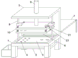
FIG. 1 is a schematic structural view of a punching device for processing a generator housing according to the present invention;
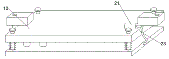
FIG. 2 is a schematic structural view of the upper die assembly for punching of the present invention;
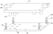
FIG. 3 is an exploded view of the upper die assembly for punching;
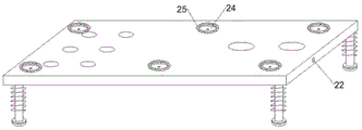
FIG. 4 is a schematic view of the structure of the limiting template of the present invention;
in the figure: 1. a support table; 2. a waste conveyor; 3. punching a lower die; 4. punching holes in a penetrating lower die; 5. a support frame; 6. a strip-shaped feed chute; 7. a feeding conveyor belt; 8. a limiting rod; 9. a hydraulic lever; 10. punching an upper die assembly; 11. stamping the template; 12. a limiting block; 13. a punching die head; 14. limiting the template; 15. a limiting component; 16. punching a hole on a through type upper die; 17. a limiting rod body; 18. a limiting plate; 19. a limiting buffer spring; 20. a limiting hole; 21. a micro air pump; 22. an air inlet and outlet hole; 23. a hose; 24. a negative pressure suction groove; 25. a rubber sealing ring.
Detailed Description
The technical solutions in the embodiments of the present invention will be clearly and completely described below with reference to the drawings in the embodiments of the present invention, and it is obvious that the described embodiments are only some embodiments of the present invention, not all embodiments; based on the embodiments in the present invention, all other embodiments obtained by a person skilled in the art without creative work belong to the protection scope of the present invention.
Given by figures 1 and 2, the utility model discloses a punching device for processing a generator housing comprises a supporting table 1, supporting legs are fixedly arranged at four corners of the bottom end of the supporting table 1, a waste conveyor belt 2 is arranged at the bottom of the supporting table 1, a waste material receiving box is arranged at one end of the waste conveyor belt 2, a punching lower die 3 is fixedly arranged in the supporting table 1, a plurality of penetrating lower die punching holes 4 are formed in the punching lower die 3, a supporting frame 5 is fixedly arranged at the top end of the supporting table 1, a strip-shaped feeding groove 6 is formed at the bottom end of the supporting frame 5, a feeding conveyor belt 7 is arranged at the back surface of the supporting frame 5, a plurality of limiting rods 8 are fixedly arranged between the supporting frame 5 and the supporting table 1, a hydraulic rod 9 inserted in the supporting frame 5 is fixedly arranged at the middle position of the top end of the supporting frame 5, and an upper punching die assembly 10 sleeved on the limiting rods 8 is fixedly arranged at the bottom end of the hydraulic rod 9;
as shown in fig. 1 to 4, the upper punching die assembly 10 comprises a punching die plate 11, a plurality of limiting blocks 12, a plurality of punching die heads 13, a limiting die plate 14 and a plurality of limiting assemblies 15, and can realize punching operation, and can limit and press the sheet material during punching to improve the punching effect, the limiting blocks 12 are fixedly connected to two ends of the top of the punching die plate 11, the limiting blocks 12 are sleeved on a limiting rod 8, the punching die heads 13 are fixedly connected to the bottom end of the punching die plate 11 and are inserted into the limiting die plate 14, the limiting die plate 14 is connected to the bottom of the punching die plate 11 through the limiting assemblies 15, the limiting die plate 14 is provided with a plurality of penetrating upper die punching holes 16 matched with the punching die heads 13, and the limiting assemblies 15 comprise a limiting rod body 17, a limiting plate 18 and a limiting buffer spring 19, the limiting template 14 can be limited, deviation is avoided, the limiting rod body 17 is fixedly connected to four corners of the top end of the limiting template 14, the limiting plate 18 is fixedly connected to the top end of the limiting rod body 17, the limiting buffer spring 19 is sleeved on the limiting rod body 17, limiting holes 20 matched with the limiting rod body 17 are formed in the four corners of the stamping template 11, a miniature air pump 21 is fixedly arranged at one end of the top of the stamping template 11, an air inlet and outlet hole 22 is formed in one end of the limiting template 14, the air inlet and outlet hole 22 is connected with the miniature air pump 21 through a hose 23, a plurality of negative pressure suction grooves 24 communicated with the air inlet and outlet hole 22 are formed in the bottom end of the limiting template 14, a rubber sealing ring 25 is fixedly arranged at the edge of the negative pressure suction grooves 24, the bottom end of the rubber sealing ring 25 is parallel to the bottom end of the limiting template 14, and blanking can be assisted;
during the use, generator housing body panel after cutting conveys through pay-off conveyer belt 7, make panel pass through bar feed chute 6 and enter into the top of brace table 1, then carry out the accuracy and place through manual work or manipulator, make panel card go into the inside of the spacing groove on punching a hole lower mould 3 top, hydraulic stem 9 drives punch a hole upper die assembly 10 and wholly push down and carry out punching work, punch a hole upper die assembly 10 during operation, spacing template 14 contacts with panel earlier, can realize the vertical spacing of spacing template 14 through spacing subassembly 15, avoid it to squint, in-process that upper die assembly 10 continues to push down in punching a hole, spacing buffer spring 19 assists spacing template 14 to compress tightly panel, effectively improve the stability of panel, avoid panel to take place the circumstances such as stick up the limit when the punching a hole, warp, shift, can realize the operation of punching a hole after punching a hole die head 13 contacts with panel, the waste material that the punching a hole produced arranges to the top of waste material conveyer belt 2, convey waste material to the inside of waste material receiver box through waste material conveyer belt 2 and collect, after punching a hole is accomplished, miniature air pump 21 begins to bleed, because the suction groove 24 closely laminates with panel this moment, consequently, can leave in-process and drive lower mould assembly 10 and punch a hole 3 effectively improve punching a hole processing efficiency, thereby it is convenient to carry out the unloading efficiency.
In the work, the waste conveyor belt and the waste receiving box are arranged, so that the punched waste can be conveniently collected in a centralized manner, and the strip-shaped feeding groove and the feeding conveyor belt are arranged, so that the auxiliary feeding can be realized, and the work efficiency is effectively improved; through the mould subassembly on punching a hole that sets up to be constituted by punching press template, a plurality of stopper, a plurality of die heads that punch a hole, spacing template and a plurality of spacing subassemblies, can realize carrying out spacing compressing tightly to generator housing panel, avoid the process of punching a hole panel to take place to shift, stick up the limit, the condition such as deformation, improve the effect of punching a hole, inhale groove and rubber seal through being provided with miniature air pump, air inlet and outlet hole, hose, negative pressure, can inhale panel after the completion of punching a hole to can assist the unloading.