CN218744228U - A kind of stamping and forming equipment for battery case - Google Patents
A kind of stamping and forming equipment for battery case Download PDFInfo
- Publication number
- CN218744228U CN218744228U CN202223338049.7U CN202223338049U CN218744228U CN 218744228 U CN218744228 U CN 218744228U CN 202223338049 U CN202223338049 U CN 202223338049U CN 218744228 U CN218744228 U CN 218744228U
- Authority
- CN
- China
- Prior art keywords
- clamping
- stamping
- battery case
- block
- forming equipment
- Prior art date
- Legal status (The legal status is an assumption and is not a legal conclusion. Google has not performed a legal analysis and makes no representation as to the accuracy of the status listed.)
- Active
Links
Images


Landscapes
- Battery Electrode And Active Subsutance (AREA)
Abstract
Description
技术领域technical field
本实用新型涉及电池壳生产设备技术领域,具体涉及一种电池壳冲压成型设备。The utility model relates to the technical field of battery case production equipment, in particular to a battery case stamping forming equipment.
背景技术Background technique
随着科技的发展和进步,电动车也越来越普及,同时对动力电池的需求也越来越多,目前动力电池不仅仅用在电动汽车上,我们常见的电单车、环卫三轮车、高尔夫球车以及一些警用巡逻车等均是通过动力电池提供动力的,动力电池通常包括动力电池外壳和由多个单体电池组成且容纳在动力电池外壳内的动力电池模组,动力电池外壳用于保护动力电池模组。电池壳实际生产的时候,需要人工将由一模具冲压的半成品运送至下一工位进行冲压,严重影响生产效率。With the development and progress of science and technology, electric vehicles are becoming more and more popular, and the demand for power batteries is also increasing. At present, power batteries are not only used in electric vehicles, but also in our common motorcycles, sanitation tricycles, golf balls, etc. Cars and some police patrol cars are powered by power batteries. The power battery usually includes a power battery casing and a power battery module composed of multiple single batteries and accommodated in the power battery casing. The power battery casing is used for Protect the power battery module. During the actual production of the battery case, it is necessary to manually transport the semi-finished product stamped by one mold to the next station for stamping, which seriously affects the production efficiency.
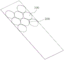
公开号为CN115318914A的发明专利公开了一种新能源电池壳推送装置及锂电池生产线,该新能源电池壳推送装置通过第一拉线机构和第二拉线机构带动推送板移动,进而带动半成品在锂电池生产线自动移位,并经多个模具依次冲压加工,提高生产效率,解决传统技术中存在的问题。结合说明书及附图可知,该锂电池生产线通过送料设备输入料卷,且设置切片模具进行切片使该锂电池生产线上不断产出料片。参阅图1,为料卷的结构,经切片模具加工后的料卷形成废卷,废卷上形成切片位100,相邻两切片位100之间形成连接边200,废卷由收卷装置进行收卷,而因连接边200结构细小,在收卷过程中废卷易发生断裂,需由人工将废卷重新收卷至收卷装置上,而该过程需要停止生产线的冲压工作,严重影响生产效率。The invention patent with the publication number CN115318914A discloses a new energy battery case push device and a lithium battery production line. The new energy battery case push device drives the push plate to move through the first wire-drawing mechanism and the second wire-drawing mechanism, and then drives the semi-finished product in the lithium battery. The production line is automatically shifted and punched sequentially through multiple molds to improve production efficiency and solve the problems existing in traditional technologies. It can be seen from the description and the accompanying drawings that the lithium battery production line inputs material rolls through the feeding equipment, and a slicing die is set for slicing so that the lithium battery production line continuously produces material sheets. Referring to Figure 1, it is the structure of the material roll. The material roll processed by the slicing mold forms a waste roll, and a
因此,有必要提供一种技术方案来解决上述问题。Therefore, it is necessary to provide a technical solution to solve the above problems.
实用新型内容Utility model content
本实用新型提供一种电池壳冲压成型设备,旨在解决现有的电池壳生产线常采用切片模具在料卷上切出料片,而裁切后的废卷在收卷过程中易发生断裂,需停止冲压,并由人工将废卷重新收卷至收卷装置上,导致生产效率低下的问题。The utility model provides a stamping and forming equipment for battery shells, which aims to solve the problem that the existing battery shell production line often uses a slicing die to cut out material pieces on the material rolls, and the waste rolls after cutting are prone to breakage during the winding process. It is necessary to stop stamping and manually rewind the waste rolls to the winding device, resulting in low production efficiency.
为实现上述目的,本实用新型提供一种电池壳冲压成型设备,包括机台、送料机械手、上料机构和若干冲压模具;其中:In order to achieve the above purpose, the utility model provides a stamping and forming equipment for a battery case, including a machine table, a feeding manipulator, a feeding mechanism and several stamping dies; wherein:
若干所述冲压模具均匀分布于所述机台上,并与所述机台连接;Several stamping dies are evenly distributed on the machine platform and connected with the machine platform;
所述送料机械手包括两条夹料臂及若干夹料组件;两条所述夹料臂分布于若干所述冲压模具的两侧,若干所述夹料组件均匀分布在两条所述夹料臂的相对面上,所述夹料组件上设有检测组件;所述机台上安装有用以驱动两条所述夹料臂沿Y轴方向相向或背向活动的第一驱动组件以及用以驱动两条所述夹料臂沿X轴方向滑动的第二驱动组件;The feeding manipulator includes two clamping arms and several clamping components; the two clamping arms are distributed on both sides of some of the stamping dies, and some of the clamping components are evenly distributed on the two clamping arms On the opposite surface, the clamping component is provided with a detection component; the machine table is equipped with a first drive component for driving the two clamping arms to move toward or away from each other along the Y-axis direction and for driving a second drive assembly for sliding the two clamping arms along the X-axis direction;
所述上料机构设于所述送料机械手的一侧,其包括底架、料片放置组件和取料组件;所述料片放置组件安装在所述底架上;所述取料组件设于所述料片放置组件上方,且位于两条所述夹料臂之间,其安装在所述底架上。The feeding mechanism is arranged on one side of the feeding manipulator, which includes an underframe, a material placing component and a material taking component; the material placing component is installed on the bottom frame; the material taking component is arranged on The material sheet is placed above the component and between the two clamping arms, which are installed on the bottom frame.
更为具体的,所述夹料组件包括夹料块;所述夹料块固定连接在所述夹料臂上,其远离所述夹料臂的一端开设有夹槽。More specifically, the material clamping assembly includes a material clamping block; the material clamping block is fixedly connected to the material clamping arm, and a clamping groove is opened at an end far away from the material clamping arm.
更为具体的,所述检测组件包括固定块、滑动杆、检测块、弹簧和第一传感器;所述固定块安装在所述夹料块靠近所述夹料臂的一端;所述滑动杆与所述固定块滑动连接,其可沿Y轴方向滑动,该滑动杆一端置于所述夹槽内;所述固定块中部开设有滑孔,所述检测块设于所述滑孔内,并与所述滑动杆固定连接;所述弹簧设于所述检测块远离所述夹料块的一侧,其套设在所述滑动杆上,且两端分别与所述检测块和所述滑孔的孔壁相贴触;所述第一传感器设于所述检测块的外侧,并安装在所述固定块上。More specifically, the detection assembly includes a fixed block, a sliding rod, a detection block, a spring and a first sensor; the fixed block is installed at one end of the clamping block close to the clamping arm; the sliding rod and The fixed block is slidably connected, and it can slide along the Y-axis direction. One end of the sliding rod is placed in the clamping groove; a sliding hole is opened in the middle of the fixed block, and the detection block is arranged in the sliding hole, and It is fixedly connected with the sliding rod; the spring is arranged on the side of the detection block away from the material clamping block, it is sleeved on the sliding rod, and the two ends are connected with the detection block and the sliding rod respectively. The walls of the holes are in contact with each other; the first sensor is arranged on the outside of the detection block and installed on the fixed block.
更为具体的,所述机台两侧分别设有安装座;所述第一驱动组件设有两组,两组所述第一驱动组件分别安装在两所述安装座上,所述夹料臂的两端分别与两组所述第一驱动组件连接;所述第二驱动组件安装在任一所述安装座上,两条所述夹料臂靠近所述第二驱动组件的一端与该第二驱动组件连接。More specifically, mounting bases are respectively provided on both sides of the machine table; two sets of the first drive assembly are provided, and the first drive assembly of the two groups is installed on the two mounting bases respectively, and the clamping material The two ends of the arm are respectively connected with two groups of the first driving assemblies; the second driving assemblies are installed on any of the mounting bases, and the ends of the two clamping arms close to the second driving assemblies are connected to the first driving assemblies. Two driving components are connected.
更为具体的,所述第一驱动组件包括第一电机、双向丝杆和两个滑座;两个所述滑座分别滑动连接在所述安装座上,其可沿Y轴方向滑动;所述双向丝杆转动连接在所述安装座上,两个所述滑座分别与所述双向丝杆的正螺纹段和反螺纹段螺纹连接;两条所述夹料臂的端部与对应的所述滑座限位式滑动连接;所述第一电机安装在所述安装座上,其用以驱动所述双向丝杆旋转。More specifically, the first drive assembly includes a first motor, a two-way screw and two sliding seats; the two sliding seats are respectively slidably connected to the mounting seats, which can slide along the Y-axis direction; The two-way screw rod is rotatably connected to the mounting seat, and the two slide seats are threadedly connected with the positive thread section and the reverse thread section of the two-way screw rod respectively; the ends of the two clamping arms are connected with the corresponding The sliding seat is limited and slidingly connected; the first motor is installed on the mounting seat, which is used to drive the two-way screw to rotate.
更为具体的,所述第二驱动组件包括连接臂、第二电机和螺杆;所述连接臂滑动连接在所述安装座上,其可沿X轴方向滑动;所述螺杆转动连接在所述安装座上,所述连接臂与所述螺杆螺纹连接;所述第二电机安装在所述安装座上,其用以驱动所述螺杆旋转;两条所述夹料臂分别与所述连接臂限位式滑动连接。More specifically, the second drive assembly includes a connecting arm, a second motor, and a screw; the connecting arm is slidably connected to the mounting base, and can slide along the X-axis direction; the screw is rotatably connected to the On the mounting base, the connecting arm is threadedly connected with the screw rod; the second motor is mounted on the mounting base, and it is used to drive the screw rod to rotate; the two clamping arms are respectively connected to the connecting arm Limited sliding connection.
更为具体的,所述料片放置组件包括分割器、工位盘和若干挡料架组;所述分割器安装在所述底架上;所述工位盘与所述分割器的输出端连接;若干所述挡料架组呈圆周阵列分布于所述工位盘的顶部,所述挡料架组包括若干挡料架,若干所述挡料架均安装在所述工位盘上,各所述挡料架组的中部设有由若干所述挡料架围设形成的容置腔;所述取料组件设于所述挡料架组的上方,其与所述容置腔的位置相对应。More specifically, the tablet placement assembly includes a divider, a station plate and several material stopper groups; the divider is installed on the chassis; the station plate and the output end of the divider connection; several of the stopper groups are distributed in a circular array on the top of the station plate, and the stopper group includes a number of stoppers, and several of the stoppers are installed on the station plate, The middle part of each of the retaining frame groups is provided with an accommodating chamber surrounded by several of the retaining racks; corresponding to the location.
更为具体的,所述取料组件包括支架、第一气缸和真空吸头;所述支架安装在所述底架上;所述第一气缸安装在所述支架上;所述真空吸头设于所述挡料架组的上方,其由所述第一气缸驱动升降滑动。More specifically, the material taking assembly includes a bracket, a first air cylinder and a vacuum suction head; the bracket is installed on the chassis; the first air cylinder is installed on the bracket; the vacuum suction head is set Above the material stopper group, it is driven to lift and slide by the first air cylinder.
更为具体的,所述第一气缸的输出端安装有升降板,所述真空吸头与所述升降板固定连接;所述真空吸头的外侧设有第二传感器,所述第二传感器与所述升降板固定连接。More specifically, a lifting plate is installed on the output end of the first cylinder, and the vacuum suction head is fixedly connected with the lifting plate; a second sensor is provided on the outside of the vacuum suction head, and the second sensor is connected to the lifting plate. The lifting plate is fixedly connected.
更为具体的,所述工位盘在对应所述容置腔的位置开设有顶料孔,所述顶料孔的宽度小于所述容置腔的宽度;所述工位盘下方设有第二气缸,所述第二气缸安装在所述底架上;所述第二气缸的上方设有顶板,所述顶板与所述第二气缸的输出端固定连接,其与所述顶料孔的位置相对应;所述支架安装有支撑板,所述支撑板位于所述挡料架组的上方,且位于所述取料组件的下方,所述支撑板在对应所述取料组件的位置处开设有上料孔;所述上料孔内设有呈圆周阵列排布的若干限位块,所述限位块中部开设有活动孔,所述活动孔内设有转轴;所述转轴上转动连接有支撑块,所述支撑块的端部伸至所述活动孔外,该支撑块的底部设有倾斜设置的导动面;所述转轴上设有扭簧,所述扭簧一端与所述限位块连接,另一端与所述支撑块连接。More specifically, the station plate is provided with a material ejection hole at a position corresponding to the accommodation cavity, and the width of the ejection hole is smaller than the width of the accommodation cavity; Two cylinders, the second cylinder is installed on the underframe; the top of the second cylinder is provided with a top plate, the top plate is fixedly connected with the output end of the second cylinder, and it is connected with the top material hole The positions are corresponding; the bracket is equipped with a support plate, the support plate is located above the material blocking frame group, and is located below the material taking assembly, and the support plate is at the position corresponding to the material taking assembly There is a feeding hole; the feeding hole is provided with a number of limit blocks arranged in a circular array, and a movable hole is opened in the middle of the limit block, and a rotating shaft is arranged in the movable hole; the rotating shaft rotates A support block is connected, the end of the support block extends out of the movable hole, the bottom of the support block is provided with an inclined guide surface; the rotating shaft is provided with a torsion spring, and one end of the torsion spring is connected to the The limit block is connected, and the other end is connected with the support block.
本实用新型所涉及的电池壳冲压成型设备的技术效果为:The technical effects of the stamping and forming equipment for the battery case involved in the utility model are as follows:
1、本申请以上料机构进行料片的上料,通过外部的裁切设备先裁切出料片,再将若干料片置于料片放置组件上,随后由取料组件将料片放置组件上的料片逐一取出,并由送料机械手进行输送,使料片经若干冲压模具依次进行冲压加工,最终得到电池壳成品。采用上述设计,使得该电池壳冲压成型设备无需因料卷的收卷问题而停机,提高生产效率。1. In this application, the material is loaded by the upper feeding mechanism, and the material is first cut out by an external cutting device, and then a number of materials are placed on the material placement component, and then the material is placed on the material by the material taking component. The blanks on the battery are taken out one by one, and conveyed by the feeding manipulator, so that the blanks are stamped sequentially through several stamping dies, and finally the finished battery case is obtained. With the above-mentioned design, the stamping and forming equipment for the battery case does not need to be shut down due to the winding problem of the material roll, and the production efficiency is improved.
2、本申请的送料机械手对半成品进行输送时,由第一驱动组件驱动两条夹料臂沿Y轴方向相向滑动,使两夹料臂上对应的夹料组件夹合半成品后,再由检测组件对夹料组件是否夹紧半成品进行判定,当检测组件判定两夹料组件未夹紧半成品时,检测组件则将信息反馈以驱使该电池壳冲压成型设备停止工作,由工作人员进行维修调整。采用上述设计,可及时检测到夹料组件未能夹紧半成品的情况,即检测到机械手未能正常将半成品带动移位,进而可及时进行停机维修,避免造成冲压模具的损坏。2. When the feeding manipulator of this application transports the semi-finished product, the first driving component drives the two clamping arms to slide towards each other along the Y-axis direction, so that the corresponding clamping components on the two clamping arms clamp the semi-finished product, and then the detection The component judges whether the clamping component is clamping the semi-finished product. When the detection component determines that the two clamping components are not clamping the semi-finished product, the detection component will feed back the information to drive the battery case stamping and forming equipment to stop working, and the staff will perform maintenance and adjustment. With the above design, it can be detected in time that the clamping component fails to clamp the semi-finished product, that is, it is detected that the manipulator fails to move the semi-finished product normally, and then the machine can be shut down for maintenance in time to avoid damage to the stamping die.
附图说明Description of drawings
图1为料卷的结构示意图;Fig. 1 is the structural representation of material roll;
图2为本实用新型所涉及的一种电池壳冲压成型设备的结构示意图;Fig. 2 is a structural schematic diagram of a battery case stamping and forming equipment involved in the present invention;
图3为本实用新型所涉及的一种电池壳冲压成型设备中送料机械手的结构示意图;Fig. 3 is a structural schematic diagram of a feeding manipulator in a battery shell stamping and forming equipment involved in the present invention;
图4为图3中A处的放大示意图;Fig. 4 is the enlarged schematic diagram of place A in Fig. 3;
图5为本实用新型所涉及的一种电池壳冲压成型设备中检测组件的结构示意图;Fig. 5 is a schematic structural diagram of a detection component in a stamping and forming equipment for a battery case involved in the present invention;
图6为本实用新型所涉及的一种电池壳冲压成型设备中第二驱动组件的结构示意图;Fig. 6 is a schematic structural diagram of the second drive assembly in a battery case stamping and forming equipment involved in the present invention;
图7为本实用新型所涉及的一种电池壳冲压成型设备中第一驱动组件的结构示意图;Fig. 7 is a structural schematic diagram of the first drive assembly in a battery case stamping and forming equipment involved in the present invention;
图8为本实用新型所涉及的一种电池壳冲压成型设备中上料机构的结构示意图;Fig. 8 is a structural schematic diagram of a feeding mechanism in a battery case stamping and forming equipment involved in the present invention;
图9为本实用新型所涉及的一种电池壳冲压成型设备中上料机构的右视图;Fig. 9 is a right view of the feeding mechanism in a battery case stamping and forming equipment involved in the present invention;
图10为本实用新型所涉及的一种电池壳冲压成型设备中取料组件的结构示意图;Fig. 10 is a structural schematic diagram of a retrieving assembly in a battery case stamping and forming equipment involved in the present invention;
图11为本实用新型所涉及的一种电池壳冲压成型设备中限位块的结构示意图。Fig. 11 is a structural schematic diagram of a limit block in a stamping and forming equipment for a battery case involved in the present invention.
图中标记:Marked in the figure:
1—机台;2—送料机械手;3—上料机构;4—冲压模具;1—machine platform; 2—feeding manipulator; 3—feeding mechanism; 4—stamping die;
11—安装座;11—mounting seat;
21—夹料臂;22—夹料组件;221—夹料块;222—夹槽;23—检测组件;231—固定块;232—滑动杆;233—检测块;234—第一传感器;24—第一驱动组件;241—第一电机;242—双向丝杆;243—滑座;25—第二驱动组件;251—连接臂;252—螺杆;21—clamping arm; 22—clamping component; 221—clamping block; 222—clamping groove; 23—detection component; 231—fixed block; 232—sliding rod; 233—detection block; 234—first sensor; 24 —the first drive assembly; 241—the first motor; 242—two-way screw; 243—slider; 25—the second drive assembly; 251—connecting arm; 252—screw;
31—底架;32—料片放置组件;321—分割器;322—工位盘;323—挡料架;324—顶料孔;325—第二气缸;326—顶板;327—容置腔;33—取料组件;331—支架;332—第一气缸;333—真空吸头;334—升降板;335—第二传感器;336—支撑板;337—上料孔;338—限位块;339—活动孔;340—转轴;341—支撑块;342—扭簧;343—第三传感器;31—bottom frame; 32—blank placement component; 321—divider; 322—station plate; 323—retaining frame; 324—top material hole; 325—second cylinder; 326—top plate; 327—accommodating cavity ; 33—feeding assembly; 331—support; 332—first cylinder; 333—vacuum suction head; ; 339—active hole; 340—rotating shaft; 341—support block; 342—torsion spring; 343—the third sensor;
具体实施方式Detailed ways
为了使本实用新型的目的、技术方案及优点更加清楚明白,以下结合附图及实施例,对本实用新型进行进一步详细说明。应当理解,此处所描述的具体实施例仅仅用以解释本实用新型,并不用于限定本实用新型。In order to make the purpose, technical solution and advantages of the utility model clearer, the utility model will be further described in detail below in conjunction with the accompanying drawings and embodiments. It should be understood that the specific embodiments described here are only used to explain the utility model, and are not intended to limit the utility model.
需要说明的是,当元件被称为“固定于”或“设置于”另一个元件,它可以直接在另一个元件上或者可能同时存在居中元件;当一个元件被称为是“连接于”另一个元件,它可以是直接连接到另一个元件或者可能同时存在居中元件。It should be noted that when an element is referred to as being "fixed" or "disposed on" another element, it may be directly on the other element or there may be an intervening element at the same time; when an element is referred to as being "connected to" another An element that may be directly connected to another element or may also have intervening elements.
此外,术语“第一”、“第二”仅用于描述目的,而不能理解为指示或暗示相对重要性或者隐含指明所指示的技术特征的数量。由此,限定有“第一”、“第二”的特征可以明示或者隐含地包括一个或者更多个该特征。在本实用新型的描述中,“多个”的含义是两个或两个以上,除非另有明确具体的限定。In addition, the terms "first" and "second" are used for descriptive purposes only, and cannot be interpreted as indicating or implying relative importance or implicitly specifying the quantity of indicated technical features. Thus, a feature defined as "first" and "second" may explicitly or implicitly include one or more of these features. In the description of the present utility model, "plurality" means two or more, unless otherwise specifically defined.
在本实用新型实施例的描述中,需要理解的是,“上”、“下”、“前”、“后”、“左”、“右”、“顶”、“底”“内”、“外”等指示的方位或位置关系为基于附图所示的方位或位置关系,仅是为了便于描述本实用新型实施例和简化描述,而不是指示或暗示所指的装置或元件必须具有特定的方位、以特定的方位构造和操作,因此不能理解为对本实用新型的限制。In the description of the embodiments of the present utility model, it should be understood that "up", "down", "front", "rear", "left", "right", "top", "bottom", "inside", The orientation or positional relationship indicated by "outside" is based on the orientation or positional relationship shown in the drawings, and is only for the convenience of describing the embodiment of the present utility model and simplifying the description, rather than indicating or implying that the referred device or element must have a specific Orientation, construction and operation in a specific orientation, and therefore should not be construed as limiting the utility model.
为了更清楚地说明本实用新型的技术方案,以下提供一优选实施例。具体参阅图1~图11。一种电池壳冲压成型设备,包括机台1、送料机械手2、上料机构3和若干冲压模具4;其中:In order to illustrate the technical solution of the present utility model more clearly, a preferred embodiment is provided below. Refer to Figure 1 to Figure 11 for details. A stamping and forming equipment for a battery case, including a
若干所述冲压模具4均匀分布于所述机台1上,并与所述机台1连接;Several stamping dies 4 are evenly distributed on the
所述送料机械手2包括两条夹料臂21及若干夹料组件22;两条所述夹料臂21分布于若干所述冲压模具4的两侧,若干所述夹料组件22均匀分布在两条所述夹料臂21的相对面上,所述夹料组件22上设有检测组件23;所述机台1上安装有用以驱动两条所述夹料臂21沿Y轴方向相向或背向活动的第一驱动组件24以及用以驱动两条所述夹料臂21沿X轴方向滑动的第二驱动组件25;The
所述上料机构3设于所述送料机械手2的一侧,其包括底架31、料片放置组件32和取料组件33;所述料片放置组件32安装在所述底架31上;所述取料组件33设于所述料片放置组件32上方,且位于两条所述夹料臂21之间,其安装在所述底架31上。The
在本实施例中,以上料机构3进行料片的上料,通过外部的裁切设备先裁切出料片,再将若干料片置于料片放置组件32上,随后由取料组件33将料片放置组件32上的料片逐一取出,并由送料机械手2进行输送,使料片经若干冲压模具4依次进行冲压加工,最终得到电池壳成品。采用上述设计,使得该电池壳冲压成型设备无需因料卷的收卷问题而停机,提高生产效率。In this embodiment, the
进一步的,传统的送料机械手2上未设置检测机构,进而送料机械手2因故障或存在外部干扰而导致未正常夹持半成品时,设备无法第一时间检测到,而半成品未正常移动至下一冲压工位处,冲压模具4却正常合模时,二者会出现非正常碰撞而导致模具受损。故本实施例中,在送料机械手2上设置检测组件23对送料机械手2的夹料状态进行检测,具体的,送料机械手2工作时,由第一驱动组件24驱动两条夹料臂21沿Y轴方向相向滑动,使两夹料臂21上对应的夹料组件22夹合半成品,而此过程中由检测组件23对夹料组件22是否夹紧半成品进行判定,若检测组件23判定两夹料组件22未夹紧半成品时,检测组件23则将信息反馈以驱使该电池壳冲压成型设备停止工作,由工作人员进行维修调整。采用上述设计,可及时检测到夹料组件22未能夹紧半成品的情况,即检测到机械手未能正常将半成品带动移位,进而可及时进行停机维修,避免造成冲压模具4的损坏。Furthermore, the
作为本实施例的优选方案,所述夹料组件22包括夹料块221;所述夹料块221固定连接在所述夹料臂21上,其远离所述夹料臂21的一端开设有夹槽222。具体的,所述第一驱动组件24驱动两条所述夹料臂21相向滑动时,两条所述夹料臂21上相对应的所述夹料块221则相靠近,直至半成品置入上述两夹料块221的所述夹槽222内,所述夹槽222的槽壁与半成品相贴触,使半成品被两所述夹料块221夹紧固定,随后所述第二驱动组件25控制两条所述夹料臂21沿X轴方向滑动,使半成品被带至移位,完成半成品的移位工作后,所述第一驱动组件24和所述第二驱动组件25配合控制两条所述夹料臂21复位,以便进行带动半成品进行下一次移位。As a preferred solution of this embodiment, the
作为本实施例的优选方案,所述检测组件23包括固定块231、滑动杆232、检测块233、弹簧(图中未示出)和第一传感器234;所述固定块231安装在所述夹料块221靠近所述夹料臂21的一端;所述滑动杆232与所述固定块231滑动连接,其可沿Y轴方向滑动,该滑动杆232一端置于所述夹槽222内;所述固定块231中部开设有滑孔,所述检测块233设于所述滑孔内,并与所述滑动杆232固定连接;所述弹簧设于所述检测块233远离所述夹料块221的一侧,其套设在所述滑动杆232上,且两端分别与所述检测块233和所述滑孔的孔壁相贴触;所述第一传感器234设于所述检测块233的外侧,并安装在所述固定块231上。具体的,两条所述夹料臂21相向活动进行半成品的夹持工作时,半成品则逐渐进入所述夹槽222内,并将所述滑动杆232顶动,所述滑动杆232带动所述检测块233移动,当所述第一传感器234检测到所述检测块233移动至其前侧时,则判定所述夹料块221移动到位,已将半成品夹紧固定,进而所述第二驱动组件25则启动以带动半成品移位,反之,若所述第一传感器234未检测到检测块233时,所述第二驱动组件25则不会启动,冲床亦不会带动冲压模具4合模,避免造成冲压模具的受损。As a preferred solution of this embodiment, the
作为本实施例的优选方案,所述机台1两侧分别设有安装座11;所述第一驱动组件24设有两组,两组所述第一驱动组件24分别安装在两所述安装座11上,所述夹料臂21的两端分别与两组所述第一驱动组件24连接;所述第二驱动组件25安装在任一所述安装座11上,两条所述夹料臂21靠近所述第二驱动组件25的一端与该第二驱动组件25连接。As a preferred solution of this embodiment, the two sides of the machine table 1 are respectively provided with mounting
进一步的,所述第一驱动组件24包括第一电机241、双向丝杆242和两个滑座243;两个所述滑座243分别滑动连接在所述安装座11上,其可沿Y轴方向滑动;所述双向丝杆242转动连接在所述安装座11上,两所述滑座243分别与所述双向丝杆242的正螺纹段和反螺纹段螺纹连接;两条所述夹料臂21的端部与对应的所述滑座243限位式滑动连接,此处的限位式滑动连接是指滑座243能够带动夹料臂21沿Y轴方向同步移动,夹料臂21能够相对滑座243沿X轴方向滑动;所述第一电机241安装在所述安装座11上,其用以驱动所述双向丝杆242旋转。所述第一电机241驱动所述双向丝杆242旋转时,在所述双向丝杆242与所述滑座243的螺纹配合下,两所述滑座243相向或背向滑动,进而带动两条所述夹料臂21相向或背向滑动以进行夹料工作。Further, the
进一步的,所述第二驱动组件25包括连接臂251、第二电机和螺杆252;所述连接臂251滑动连接在所述安装座11上,其可沿X轴方向滑动;所述螺杆252转动连接在所述安装座11上,所述连接臂251与所述螺杆252螺纹连接;所述第二电机安装在所述安装座11上,其用以驱动所述螺杆252旋转;两条所述夹料臂21分别与所述连接臂251限位式滑动连接,此处的限位式滑动连接是指连接臂251能够带动夹料臂21沿X轴方向同步移动,夹料臂21能够相对连接臂251沿Y轴方向滑动。所述第二电机驱动所述螺杆252旋转时,在所述螺杆252与所述连接臂251的配合下,所述连接臂251则沿X轴方向进行滑动,进而带动两条所述夹料臂21沿所述X轴方向滑动。Further, the
作为本实施例的优选方案,所述料片放置组件32包括分割器321、工位盘322和若干挡料架组323;所述分割器321安装在所述底架31上;所述工位盘322与所述分割器321的输出端连接;若干所述挡料架组323呈圆周阵列分布于所述工位盘322的顶部,所述挡料架组323包括若干挡料架,若干所述挡料架均安装在所述工位盘322上,各所述挡料架组323的中部设有由若干所述挡料架围设形成的容置腔327;所述取料组件33设于所述挡料架组323的上方,其与所述容置腔327的位置相对应。具体的,料片放置至所述容置腔327内,由所述取料组件33将所述容置腔327内的料片逐一取出,并由所述送料机械手2将所述取料组件33上的料片带动移位,当所述取料组件33对应的容置腔327内的料片完全取出后,所述分割器321则带动所述工位盘322旋转,使原位于取料组件33正下方的挡料架组323向外活动进行料片补充,而另一所述挡料架组323的容置腔327则活动至所述取料组件33的正下方,由取料组件33继续取料,如此,无需停机补充料片,提高生产效率。As a preferred solution of this embodiment, the
作为本实施例的优选方案,所述取料组件33包括支架331、第一气缸332和真空吸头333;所述支架331安装在所述底架31上;所述第一气缸332安装在所述支架331上;所述真空吸头333设于所述挡料架组323的上方,其由所述第一气缸332驱动升降滑动。具体的,所述取料组件33取料时,由所述第一气缸332驱动所述真空吸头333下行对料片进行吸附,随后所述第一气缸332的输出端回缩,以带动料片上行,待两条所述夹料臂21上的夹料组件22夹持料片后,所述真空吸头333则撤去对料片的吸力,使所述送料机械手2可带动料片移位。As a preferred solution of this embodiment, the
作为本实施例的优选方案,所述第一气缸332的输出端安装有升降板334,所述真空吸头333与所述升降板334固定连接;所述真空吸头333的外侧设有第二传感器335,所述第二传感器335与所述升降板334固定连接。所述第二传感器335用以检测所述真空吸头333是否正常吸附料片,若检测到所述真空吸头333未吸附料片时,则将信息反馈以驱使所述第一气缸332再次驱动真空吸头333下行进行料片吸取。As a preferred solution of this embodiment, a
作为本实施例的优选方案,所述工位盘322在对应所述容置腔327的位置开设有顶料孔324,所述顶料孔324的宽度小于所述容置腔327的宽度;所述工位盘322下方设有第二气缸325,所述第二气缸325安装在所述底架31上;所述第二气缸325的上方设有顶板326,所述顶板326与所述第二气缸325的输出端固定连接,其与所述顶料孔324的位置相对应;所述支架331安装有支撑板336,所述支撑板336位于所述挡料架组323的上方,且位于所述取料组件33的下方,所述支撑板336在对应所述取料组件33的位置处开设有上料孔337;所述上料孔337内设有呈圆周阵列排布的若干限位块338,所述限位块338中部开设有活动孔339,所述活动孔339内设有转轴340;所述转轴340上转动连接有支撑块341,所述支撑块341的端部伸至所述活动孔339外,该支撑块341的底部设有倾斜设置的导动面;所述转轴340上设有扭簧342,所述扭簧342一端与所述限位块338连接,另一端与所述支撑块341连接。优选的,所述上料孔337的外侧设有第三传感器343,所述第三传感器343安装在所述支撑板336上。具体的,所述第三传感器343检测到所述支撑块341的上方没有料片后,则将信息反馈以使所述第二气缸325启动,使所述第二气缸325驱动所述顶板326向上活动,所述顶板326穿过所述顶料孔324后,将所述容置腔327内的料片顶起,而在所述支撑块341底部的导动面的作用下,料片将所述支撑块341顶至旋转,使料片可活动至所述支撑块341上方,待所述顶板326上方的全部料片均活动至所述支撑块341上方后,所述支撑块341则在所述扭簧342的带动下复位,此时,若干所述支撑块341则对料片形成支撑,所述第三传感器343检测到所述支撑板336上方有料片时,则驱动所述取料组件33启动进行取料。采用上述设计,可缩短所述真空吸头333所需移动的距离,以此降低所述第一气缸332驱动所述真空吸头333上升过程中,料片脱落的可能性,提高所述取料组件33的取料稳定性。As a preferred solution of this embodiment, the
本实用新型所涉及的一种电池壳冲压成型设备,通过合理的结构设置,解决了现有的电池壳生产线常采用切片模具在料卷上切出料片,而裁切后的废卷在收卷过程中易发生断裂,需停止冲压,并由人工将废卷重新收卷至收卷装置上,导致生产效率低下的问题。The utility model relates to a battery case stamping and forming equipment, through reasonable structural settings, it solves the problem that the existing battery case production line often uses a slicing die to cut out the material sheet on the material roll, and the waste roll after cutting is collected. It is easy to break during the rolling process, and the stamping needs to be stopped, and the waste rolls must be manually rewound to the winding device, resulting in low production efficiency.
以上仅为本实用新型较佳的实施例而已,其结构并不限于上述列举的形状,凡在本实用新型的精神和原则之内所作的任何修改、等同替换和改进等,均应包含在本实用新型的保护范围。The above is only a preferred embodiment of the utility model, and its structure is not limited to the shapes listed above. Any modifications, equivalent replacements and improvements made within the spirit and principles of the utility model should be included in this utility model. Protection scope of utility model.
Claims (10)
Priority Applications (1)
| Application Number | Priority Date | Filing Date | Title |
|---|---|---|---|
| CN202223338049.7U CN218744228U (en) | 2022-12-13 | 2022-12-13 | A kind of stamping and forming equipment for battery case |
Applications Claiming Priority (1)
| Application Number | Priority Date | Filing Date | Title |
|---|---|---|---|
| CN202223338049.7U CN218744228U (en) | 2022-12-13 | 2022-12-13 | A kind of stamping and forming equipment for battery case |
Publications (1)
| Publication Number | Publication Date |
|---|---|
| CN218744228U true CN218744228U (en) | 2023-03-28 |
Family
ID=85681756
Family Applications (1)
| Application Number | Title | Priority Date | Filing Date |
|---|---|---|---|
| CN202223338049.7U Active CN218744228U (en) | 2022-12-13 | 2022-12-13 | A kind of stamping and forming equipment for battery case |
Country Status (1)
| Country | Link |
|---|---|
| CN (1) | CN218744228U (en) |
Cited By (2)
| Publication number | Priority date | Publication date | Assignee | Title |
|---|---|---|---|---|
| CN117139461A (en) * | 2023-10-31 | 2023-12-01 | 山东华莱美机械科技有限公司 | A cold stamping cutting positioning device for the production of agricultural machinery parts |
| CN119076806A (en) * | 2024-09-20 | 2024-12-06 | 无锡金杨新材料股份有限公司 | A material transfer mechanism for continuous stamping of battery processing |
-
2022
- 2022-12-13 CN CN202223338049.7U patent/CN218744228U/en active Active
Cited By (3)
| Publication number | Priority date | Publication date | Assignee | Title |
|---|---|---|---|---|
| CN117139461A (en) * | 2023-10-31 | 2023-12-01 | 山东华莱美机械科技有限公司 | A cold stamping cutting positioning device for the production of agricultural machinery parts |
| CN117139461B (en) * | 2023-10-31 | 2024-02-13 | 山东华莱美机械科技有限公司 | A cold stamping cutting positioning device for the production of agricultural machinery parts |
| CN119076806A (en) * | 2024-09-20 | 2024-12-06 | 无锡金杨新材料股份有限公司 | A material transfer mechanism for continuous stamping of battery processing |
Similar Documents
| Publication | Publication Date | Title |
|---|---|---|
| CN105689488B (en) | A kind of power battery lug cuts production line | |
| CN112692632B (en) | Milling detection equipment | |
| CN113783382A (en) | Wire winding and inserting integrated machine | |
| CN108448175A (en) | An automatic unloading and flattening mechanism of a high-speed winding machine | |
| CN208256842U (en) | A kind of high-speed winder automatic blanking flattening mechanism | |
| CN214921073U (en) | Battery tab cutting device and battery production equipment | |
| CN210847998U (en) | Die carrier convenient to drawing of patterns | |
| CN115464716A (en) | Material cutting system and material cutting method | |
| CN102848179A (en) | Buzzer placing mechanism | |
| CN111082157B (en) | Automated cell winding and packaging machine | |
| CN218532437U (en) | Auto-parts mold processing | |
| WO2025156534A1 (en) | Battery film application device and film application method thereof | |
| CN214444915U (en) | Milling inspection equipment | |
| CN217254289U (en) | Full-automatic iron sheet locking and cap pressing machine | |
| CN114713517B (en) | Automatic product size measuring equipment for irregular products | |
| CN214054335U (en) | Electricity core and cylinder manifold automatic assembly device | |
| CN211489188U (en) | A automatic stamping device of robot for watch case production | |
| CN111682266B (en) | A lithium battery automatic film pasting device | |
| CN116470113A (en) | Winding needle, winding device and winding needle outer circumference adjusting method | |
| CN111114107A (en) | An automatic solar screen printing medium reel sleeve machine | |
| CN214983130U (en) | Automatic shell punching machine for aluminum-plastic film cutting of lithium battery | |
| CN117816832B (en) | Profile stamping device, photovoltaic frame automatic production line and production method | |
| CN222921081U (en) | Filter material coil welding equipment for filter element | |
| JP4077949B2 (en) | Die pushing apparatus and die pushing method using the apparatus | |
| CN222242484U (en) | Electromagnet spin riveting device |
Legal Events
| Date | Code | Title | Description |
|---|---|---|---|
| GR01 | Patent grant | ||
| GR01 | Patent grant | ||
| TR01 | Transfer of patent right | ||
| TR01 | Transfer of patent right |
Effective date of registration: 20250523 Address after: 526000 Guangdong Province Zhaoqing City Gaoxin District Fenggang Industrial Park Science and Technology Avenue No. 9 Guangdong Orejin Packaging Co., Ltd. Beverage Workshop Patentee after: Guangdong Junyi Electromechanical Technology Co.,Ltd. Country or region after: China Address before: 523460 Guangdong Province Dongguan City Hengli Town Xin Si Youzao Village Dapian Road 11 No. Patentee before: DONGGUAN JUNYI ELECTROMECHANICAL TECHNOLOGY CO.,LTD. Country or region before: China |
|
| TR01 | Transfer of patent right | ||
| TR01 | Transfer of patent right |
Effective date of registration: 20250723 Address after: 336600 Jiangxi Province Xinyu City Fenyi County East Industrial Park Dongxing Road to the north Patentee after: Fenyi Hejun New Energy Technology Co.,Ltd. Country or region after: China Address before: 526000 Guangdong Province Zhaoqing City Gaoxin District Fenggang Industrial Park Science and Technology Avenue No. 9 Guangdong Orejin Packaging Co., Ltd. Beverage Workshop Patentee before: Guangdong Junyi Electromechanical Technology Co.,Ltd. Country or region before: China |