CN218742724U - Special flush coater of pipeline inside lining - Google Patents
Special flush coater of pipeline inside lining Download PDFInfo
- Publication number
- CN218742724U CN218742724U CN202223319140.4U CN202223319140U CN218742724U CN 218742724 U CN218742724 U CN 218742724U CN 202223319140 U CN202223319140 U CN 202223319140U CN 218742724 U CN218742724 U CN 218742724U
- Authority
- CN
- China
- Prior art keywords
- base
- support rod
- motor
- spraying
- high pressure
- Prior art date
- Legal status (The legal status is an assumption and is not a legal conclusion. Google has not performed a legal analysis and makes no representation as to the accuracy of the status listed.)
- Active
Links
Images


Landscapes
- Spray Control Apparatus (AREA)
Abstract
The utility model discloses a special spraying machine for pipeline linings, which relates to the technical field of pipeline spraying and comprises a walking mechanism, wherein a high-pressure airless spraying machine, an air pump, an explosion-proof control box and a lifting mechanism are fixedly arranged on the walking mechanism, and a rotary spraying mechanism is fixedly arranged above the lifting mechanism; the lifting mechanism comprises a base, a lifting motor, a sliding block, a sliding rod, a first support rod, a second support rod and a sliding rail, and the base is fixedly arranged on the travelling mechanism; has the advantages that: the spraying machine, the automatic spray gun, the driving trolley and the material barrel are integrated, the whole spraying process is automated, the field is unattended, and the processes of manual batching, material conveying and the like are reduced; the speed of the spraying trolley can be adjusted in the construction process, and the thickness of the coating can be adjusted; the construction speed is fast, the spraying is even, the material and the labor are saved, and 1-2 persons operate the equipment.
Description
Technical Field
The utility model relates to a pipeline spraying technical field especially relates to a special flush coater of pipeline inside lining.
Background
At present, manual construction is adopted for spraying the large-caliber long-distance buried pipeline, and in the construction process, because the space in the pipeline is limited and ventilation is poor, harmful gas emitted by paint is not easy to disperse, so that the health of constructors is influenced, the manual spraying uniformity is poor, and the labor intensity is high.
With the continuous attention of the state on HSE, the requirement of human body health is more and more urgent, and the coating is very expensive, so that the coating is greatly wasted due to uneven thickness, and the quality is difficult to be well ensured.
SUMMERY OF THE UTILITY MODEL
The utility model aims at providing a special flush coater of pipeline inside lining for solving above-mentioned problem, in the spraying construction operation process in the pipeline, realize full-automatic unmanned operation, high-pressure airless rotatory spraying to it is even to reach the coating, and the purpose of raising the efficiency strengthens environmental protection, ensures that personnel are healthy.
The utility model discloses a following technical scheme realizes above-mentioned purpose:
a pipeline lining special spraying machine comprises a travelling mechanism, wherein a high-pressure airless spraying machine, an air pump, an explosion-proof control box and a lifting mechanism are fixedly arranged on the travelling mechanism, and a rotary spraying mechanism is fixedly arranged above the lifting mechanism; the lifting mechanism comprises a base, a lifting motor, a sliding block, sliding rods, a first supporting rod, a second supporting rod and sliding rails, the base is fixedly installed on the walking mechanism, the end face of the base is U-shaped, the two parallel sliding rods are fixedly installed on the upper portion of the base, a lead screw is arranged between the sliding rods, the two ends of the lead screw are respectively connected with the base through bearings, the lifting motor is fixedly installed at one end of the base corresponding to one end of the lead screw, one end of the lead screw close to the lifting motor extends out of the side face of the base and is fixedly connected with the output end of the lifting motor, the sliding block is movably arranged above the base, the two ends of the sliding block are respectively sleeved on the two sliding rods to slide, the middle of the sliding block is connected with the lead screw through threads, scissor braces are respectively arranged above the base corresponding to the two sliding rods, and an installation plate is arranged above the scissor braces; the scissor support comprises a first support rod and a second support rod, and the middle position of the first support rod is rotatably connected with the middle position of the second support rod; the lower end of the first support rod is fixedly connected with the edge of one side of the base, which is far away from the lifting motor, through a hinge, a slide rail is fixedly installed on the installation plate corresponding to the upper end of the first support rod, and the upper end of the first support rod is clamped in the slide rail to move; the lower end of the second support rod is close to the base through a hinge and is fixedly connected to one side edge of the lifting motor, and the upper end of the second support rod is far away from the mounting plate through a hinge and is fixedly connected to one side of the sliding rail.
Preferably: the walking mechanism comprises a frame, a walking motor, a transmission gear set and moving wheels, the four corners below the frame are respectively fixedly provided with the moving wheels through bearings, the moving wheels are opposite and fixedly connected through a connecting rod, one end of the upper surface of the frame corresponds to the connecting rod, the walking motor is fixedly arranged at the position of the connecting rod, and the output end of the walking motor is in transmission connection with the connecting rod through the transmission gear set.
Preferably: the base is fixedly installed at one end, far away from the walking motor, of the upper surface of the frame, and the high-pressure airless sprayer, the air pump and the explosion-proof control box are fixedly installed in the middle of the upper surface of the frame respectively.
Preferably: rotatory spraying mechanism includes binary channels high pressure rotating ware, automatic spray gun, rotating electrical machines, mounting bracket, mounting panel and motor cabinet, the mounting panel upper surface is kept away from one side border fixed mounting of elevator motor has the mounting bracket, install binary channels high pressure rotating ware through the bearing on the mounting bracket, the mounting panel upper surface is close to one side fixed mounting of walking motor has the motor cabinet, fixed mounting has the rotating electrical machines on the motor cabinet, the rotating electrical machines with binary channels high pressure rotating ware fixed connection, high pressure airless spray painting machine with the output of air pump respectively through high-pressure hose with binary channels high pressure rotating ware sealing connection, binary channels high pressure rotating ware is kept away from the one end of rotating electrical machines sets up automatic spray gun all around respectively, automatic spray gun with binary channels high pressure rotating ware passes through pipe sealing connection.
Compared with the prior art, the beneficial effects of the utility model reside in that:
1. the spraying machine, the automatic spray gun, the driving trolley and the material barrel are integrated, the whole spraying process is automatic, the field is unattended, and the processes of manual batching, material conveying and the like are reduced.
2. The speed of the spraying trolley can be adjusted in the construction process, and the thickness of the coating can be adjusted.
3. The construction speed is fast, the spraying is even, the material and the labor are saved, and 1-2 persons operate the equipment.
Drawings
In order to more clearly illustrate the embodiments of the present invention or the technical solutions in the prior art, the drawings needed to be used in the description of the embodiments or the prior art will be briefly described below, it is obvious that the drawings in the following description are only some embodiments of the present invention, and for those skilled in the art, other drawings can be obtained according to these drawings without inventive exercise.
Fig. 1 is a schematic view of a three-dimensional structure of a special spraying machine for a pipeline lining of the present invention.
Fig. 2 is a schematic view of another perspective structure of the special coating machine for pipeline lining of the present invention.
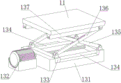
Fig. 3 is a schematic view of a three-dimensional structure of a lifting mechanism of a special coating machine for pipeline lining of the present invention.
The reference numerals are explained below:
1. a frame; 2. a high pressure airless sprayer; 3. a dual-channel high-pressure rotator; 4. an automatic spray gun; 5. a traveling motor; 6. a rotating electric machine; 8. an air pump; 9. a moving wheel; 10. a mounting frame; 11. mounting a plate; 12. a motor base; 13. a lifting mechanism; 131. a base; 132. a lifting motor; 133. a slider; 134. a slide bar; 135. a first stay bar; 136. a second stay bar; 137. a slide rail; 14. explosion-proof control box.
Detailed Description
In the description of the present invention, it is to be understood that the terms "central", "longitudinal", "lateral", "upper", "lower", "front", "rear", "left", "right", "vertical", "horizontal", "top", "bottom", "inner", "outer", and the like, indicate orientations or positional relationships based on those shown in the drawings, and are used only for convenience in describing and simplifying the description, and do not indicate or imply that the device or element being referred to must have a particular orientation, be constructed and operate in a particular orientation, and therefore are not to be construed as limiting the present invention, and further, the terms "first", "second", and the like are used only for descriptive purposes and are not intended to indicate or imply relative importance or to implicitly indicate the number of technical features being referred to, whereby the features defined as "first", "second", and the like may explicitly or implicitly include one or more such features, and in the description of the present invention, unless otherwise indicated, the terms "plurality" means two or more than two.
In the description of the present invention, it is to be noted that, unless otherwise explicitly specified or limited, the terms "mounted," "connected," and "connected" are to be construed broadly, and may be, for example, fixedly connected, detachably connected, or integrally connected; can be mechanically or electrically connected; the two elements may be directly connected or indirectly connected through an intermediate medium, or the two elements may be connected through an intermediate medium, and the specific meaning of the above terms in the present invention can be understood by those skilled in the art through specific situations.
The present invention will be further explained with reference to the accompanying drawings:
as shown in fig. 1-3, a special spraying machine for pipeline lining comprises a traveling mechanism, a high-pressure airless spraying machine 2, an air pump 8, an explosion-proof control box 14 and a lifting mechanism 13 are fixedly installed on the traveling mechanism, and a rotary spraying mechanism is fixedly installed above the lifting mechanism 13; the lifting mechanism 13 comprises a base 131, a lifting motor 132, a sliding block 133, sliding rods 134, a first supporting rod 135, a second supporting rod 136 and a sliding rail 137, the base 131 is fixedly installed on the walking mechanism, the end face of the base 131 is U-shaped, two parallel sliding rods 134 are fixedly installed on the upper portion of the base 131, a screw rod is arranged between the sliding rods 134, two ends of the screw rod are respectively connected with the base 131 through bearings, the lifting motor 132 is fixedly installed at one end of one side of the base 131 corresponding to the screw rod, one end of the screw rod close to the lifting motor 132 extends out of the side face of the base 131 and is fixedly connected with the output end of the lifting motor 132, the sliding block 133 is movably arranged above the base 131, two ends of the sliding block 133 are respectively sleeved on the two sliding rods 134 to slide, the middle of the sliding block 133 is connected with the screw rod through threads, scissor supports are respectively arranged above the base 131 corresponding to the positions above the two sliding rods 134, and a mounting plate 11 is arranged above the scissor supports; the scissor support comprises a first support rod 135 and a second support rod 136, and the middle position of the first support rod 135 is rotatably connected with the middle position of the second support rod 136; the lower end of the first support rod 135 is fixedly connected with the edge of one side of the base 131 far away from the lifting motor 132 through a hinge, a slide rail 137 is fixedly installed on the installation plate 11 corresponding to the upper end of the first support rod 135, and the upper end of the first support rod 135 is clamped in the slide rail 137 to move; the lower end of the second support rod 136 is fixedly connected with the edge of one side of the base 131 close to the lifting motor 132 through a hinge, and the upper end of the second support rod 136 is fixedly connected with one side of the mounting plate 11 far away from the slide rail 137 through a hinge; the travelling mechanism comprises a frame 1, a travelling motor 5, a transmission gear set and a travelling wheel 9, wherein the travelling wheel 9 is fixedly arranged at four corners below the frame 1 through bearings respectively, the two opposite travelling wheels 9 are fixedly connected through a connecting rod, the travelling motor 5 is fixedly arranged at one end of the upper surface of the frame 1 corresponding to the position of the connecting rod, the travelling motor 5 adopts a friction type stepless speed regulating motor, the travelling speed is digitally displayed, the speed of the trolley can be timely adjusted according to the spraying condition, and the output end of the travelling motor 5 is in transmission connection with the connecting rod through the transmission gear set; the base 131 is fixedly installed at one end, far away from the walking motor 5, of the upper surface of the frame 1, the high-pressure airless sprayer 2, the air pump 8 and the explosion-proof control box 14 are respectively and fixedly installed at the middle position of the upper surface of the frame 1, the high-pressure airless sprayer 2 adopts a pneumatic spraying machine of American Gurueli 60, the highest pressure can reach 16MPa, and the explosion-proof control box 14 is used for controlling the working state of an electric appliance part so as to realize automatic spraying; the rotary spraying mechanism comprises a double-channel high-pressure rotator 3, an automatic spray gun 4, a rotary motor 6, a mounting rack 10, a mounting plate 11 and a motor base 12, wherein the mounting rack 10 is fixedly mounted at the edge of one side, far away from a lifting motor 132, of the upper surface of the mounting plate 11, the double-channel high-pressure rotator 3 is mounted on the mounting rack 10 through a bearing, the double-channel high-pressure rotator 3 is a core component of the full-automatic high-pressure rotary airless spraying vehicle, double channels are formed in the upper surface of the mounting plate 11, because an air source is needed by the automatic spray gun 4, the rotator must provide two channels which do not interfere with each other, the pressure is not lower than 16MPa, leakage is avoided in the rotary spraying process, the motor base 12 is fixedly mounted on one side, close to a walking motor 5, the rotary motor 6 is fixedly mounted on the motor base 12, the rotary motor 6 adopts a friction type stepless speed regulating motor, the advancing speed is displayed in a digital mode, the rotary speed of the rotator can be timely regulated according to the spraying conditions, the rotary motor 6 and is fixedly connected with the double-channel high-pressure rotator 3, the output ends of the high-pressure airless spraying machine 2 and the air pump 8 are respectively in sealing connection with the high-pressure rotator 3 through a high-pressure hose, one end, the automatic spray gun 4 is respectively, and the high-pressure airless spraying mechanism is uniformly connected with the automatic spray gun 4 through the double-channel high-pressure pipeline, and the automatic spray gun 4.
The working principle is as follows: when the spraying device is used, firstly, the speed of the trolley is adjusted to be proper (the adjustment speed is tested for many times), the walking motor 5 is started to drive the trolley to move, meanwhile, the rotating motor 6 is started to drive the double-channel high-pressure rotator 3 to rotate, then, the high-pressure airless sprayer 2 is started, the air source switch of the full-automatic spray gun 4 is opened, the stirred paint is pressurized by the high-pressure airless sprayer 2 and is sprayed out in a circular fog shape from the automatic spray gun 4, and the paint is uniformly adsorbed on the inner wall of a pipeline under the action of rotating centrifugal force, so that the purpose of internal corrosion resistance is achieved.
The high-pressure airless sprayer 2, the double-channel high-pressure rotator 3, the automatic spray gun 4, the traveling motor 5, the rotating motor 6, the air pump 8, the lifting motor 132 and the explosion-proof control box 14 are all universal standard parts or parts known to those skilled in the art, and the structure and principle of the parts are known to those skilled in the art through technical manuals or conventional experimental methods, so that the description is omitted here.
Having shown and described the basic principles, essential features and advantages of the invention, it should be understood by those skilled in the art that the present invention is not limited by the foregoing embodiments, which are merely illustrative, but rather are intended to cover various changes and modifications within the spirit and scope of the invention as defined by the appended claims.
Claims (4)
1. The utility model provides a special flush coater of pipeline inside lining, includes running gear, its characterized in that: the walking mechanism is fixedly provided with a high-pressure airless sprayer (2), an air pump (8), an explosion-proof control box (14) and a lifting mechanism (13), and a rotary spraying mechanism is fixedly arranged above the lifting mechanism (13); the lifting mechanism (13) comprises a base (131), a lifting motor (132), a sliding block (133), a sliding rod (134), a first support rod (135), a second support rod (136) and a sliding rail (137), the base (131) is fixedly installed on the traveling mechanism, the end face of the base (131) is U-shaped, the two parallel sliding rods (134) are fixedly installed on the upper portion of the base (131), a screw rod is arranged between the sliding rods (134), two ends of the screw rod are respectively connected with the base (131) through bearings, the lifting motor (132) is fixedly installed at one end of one side of the base (131) corresponding to one end of the screw rod, one end of the screw rod close to the lifting motor (132) extends out of the side face of the base (131) and is fixedly connected with the output end of the lifting motor (132), the sliding block (133) is movably arranged above the base (131), two ends of the sliding block (133) are respectively sleeved on the two sliding rods (134) to slide, the middle of the sliding block (133) is connected with the screw rod through threads, the upper portion of the base (131) is respectively corresponding to the positions above the two support rods (134), and a scissor support plate (11) is arranged above the scissor; the scissor support comprises a first support rod (135) and a second support rod (136), and the middle position of the first support rod (135) is rotatably connected with the middle position of the second support rod (136); the lower end of the first support rod (135) is fixedly connected with the edge of one side, far away from the lifting motor (132), of the base (131) through a hinge, a sliding rail (137) is fixedly mounted on the mounting plate (11) corresponding to the upper end of the first support rod (135), and the upper end of the first support rod (135) is clamped in the sliding rail (137) to move; the lower end of the second support rod (136) is close to the base (131) through a hinge and is fixedly connected with the edge of one side of the lifting motor (132), and the upper end of the second support rod (136) is fixedly connected with one side of the sliding rail (137) through a hinge and the mounting plate (11).
2. The special spraying machine for the pipeline lining as claimed in claim 1, wherein: running gear includes frame (1), walking motor (5), drive gear group and removes wheel (9), frame (1) below four corners has removal wheel (9), two relatively through bearing fixed mounting respectively remove wheel (9) and pass through connecting rod fixed connection, frame (1) upper surface one end corresponds connecting rod position fixed mounting has walking motor (5), the output of walking motor (5) with the connecting rod passes through drive gear group transmission and connects.
3. The special sprayer for pipeline linings according to claim 2, characterized in that: the base (131) is fixedly installed at one end, far away from the walking motor (5), of the upper surface of the frame (1), and the high-pressure airless sprayer (2), the air pump (8) and the explosion-proof control box (14) are respectively and fixedly installed in the middle of the upper surface of the frame (1).
4. The special sprayer for pipeline linings according to claim 2, characterized in that: rotatory spraying mechanism includes binary channels high pressure rotating ware (3), automatic spray gun (4), rotating electrical machines (6), mounting bracket (10), mounting panel (11) and motor cabinet (12), mounting panel (11) upper surface is kept away from one side border fixed mounting of elevator motor (132) has mounting bracket (10), install binary channels high pressure rotating ware (3) through the bearing on mounting bracket (10), mounting panel (11) upper surface is close to one side fixed mounting of walking motor (5) has motor cabinet (12), fixed mounting has rotating electrical machines (6) on motor cabinet (12), rotating electrical machines (6) with binary channels high pressure rotating ware (3) fixed connection, high pressure airless spraying machine (2) with the output of air pump (8) respectively through high pressure hose with binary channels high pressure rotating ware (3) sealing connection, binary channels high pressure rotating electrical machines (3) are kept away from the one end of rotating electrical machines (6) sets up automatic spray gun (4) all around respectively, automatic spray gun (4) with binary channels high pressure rotating electrical machines (3) pass through pipeline sealing connection.
Priority Applications (1)
| Application Number | Priority Date | Filing Date | Title |
|---|---|---|---|
| CN202223319140.4U CN218742724U (en) | 2022-12-12 | 2022-12-12 | Special flush coater of pipeline inside lining |
Applications Claiming Priority (1)
| Application Number | Priority Date | Filing Date | Title |
|---|---|---|---|
| CN202223319140.4U CN218742724U (en) | 2022-12-12 | 2022-12-12 | Special flush coater of pipeline inside lining |
Publications (1)
| Publication Number | Publication Date |
|---|---|
| CN218742724U true CN218742724U (en) | 2023-03-28 |
Family
ID=85682576
Family Applications (1)
| Application Number | Title | Priority Date | Filing Date |
|---|---|---|---|
| CN202223319140.4U Active CN218742724U (en) | 2022-12-12 | 2022-12-12 | Special flush coater of pipeline inside lining |
Country Status (1)
| Country | Link |
|---|---|
| CN (1) | CN218742724U (en) |
Cited By (3)
| Publication number | Priority date | Publication date | Assignee | Title |
|---|---|---|---|---|
| CN116459962A (en) * | 2023-04-12 | 2023-07-21 | 苏州普利格精密科技有限公司 | Coating device and coating process for rust-proof layer on surface of machined alloy plate |
| CN117259077A (en) * | 2023-09-18 | 2023-12-22 | 杭州浙达精益机电技术股份有限公司 | An automatic rotating spray painting device |
| CN118122536A (en) * | 2023-07-17 | 2024-06-04 | 中联重科股份有限公司 | An automatic rail-fixing grease spraying system for the inner wall of an irregular tubular body |
-
2022
- 2022-12-12 CN CN202223319140.4U patent/CN218742724U/en active Active
Cited By (4)
| Publication number | Priority date | Publication date | Assignee | Title |
|---|---|---|---|---|
| CN116459962A (en) * | 2023-04-12 | 2023-07-21 | 苏州普利格精密科技有限公司 | Coating device and coating process for rust-proof layer on surface of machined alloy plate |
| CN116459962B (en) * | 2023-04-12 | 2023-12-29 | 苏州普利格精密科技有限公司 | Coating device and coating process for rust-proof layer on surface of machined alloy plate |
| CN118122536A (en) * | 2023-07-17 | 2024-06-04 | 中联重科股份有限公司 | An automatic rail-fixing grease spraying system for the inner wall of an irregular tubular body |
| CN117259077A (en) * | 2023-09-18 | 2023-12-22 | 杭州浙达精益机电技术股份有限公司 | An automatic rotating spray painting device |
Similar Documents
| Publication | Publication Date | Title |
|---|---|---|
| CN110525937A (en) | Intelligent overturning conveyor | |
| CN214864608U (en) | Suspension type double-sided automatic spraying line | |
| CN210131740U (en) | Steel-plastic composite pipe inner and outer anti-corrosion treatment device | |
| CN120227991B (en) | A painting equipment for processing doors of new energy vehicles | |
| CN213234173U (en) | Paint spraying device for interior decoration of service compartment | |
| CN210729991U (en) | Spraying device for automobile lamp production | |
| CN210418114U (en) | A gear-driven walking trolley | |
| CN208771693U (en) | A kind of exhaust pipe rotation spray-painting plant | |
| CN107597486B (en) | Spray coating method | |
| CN206881982U (en) | A kind of body of a motor car paint spraying apparatus | |
| CN218423548U (en) | Horizontal double-station spraying coating equipment | |
| CN107486357A (en) | An automatic spraying device for railway passenger car body | |
| CN220496715U (en) | Paint spraying equipment with regulatory function for automobile sheet metal | |
| CN209476520U (en) | A kind of intermetallic composite coating spraying equipment that workpiece may be reversed | |
| CN212167903U (en) | Paint spraying device for machining high-low voltage power distribution cabinet | |
| CN210828220U (en) | Putty spraying device | |
| CN220153811U (en) | Full-automatic spraying waterproof testing device for IPX5 of energy storage cabinet | |
| CN107716157B (en) | Novel spray coating method | |
| CN117282582B (en) | An electrolytic cell coating device | |
| CN220697190U (en) | Coating mechanism of thin-wall component of electric automobile | |
| CN107952610B (en) | Spraying device | |
| CN107626483B (en) | Novel spraying device | |
| CN223454441U (en) | Spraying equipment for automobile parts | |
| CN220461125U (en) | Metallic automobile sign surface coloring spraying device | |
| CN223717396U (en) | Spraying device with adjustable spraying height |
Legal Events
| Date | Code | Title | Description |
|---|---|---|---|
| GR01 | Patent grant | ||
| GR01 | Patent grant |