CN218741029U - Hydrolysis tail gas treatment device - Google Patents
Hydrolysis tail gas treatment device Download PDFInfo
- Publication number
- CN218741029U CN218741029U CN202223295128.4U CN202223295128U CN218741029U CN 218741029 U CN218741029 U CN 218741029U CN 202223295128 U CN202223295128 U CN 202223295128U CN 218741029 U CN218741029 U CN 218741029U
- Authority
- CN
- China
- Prior art keywords
- tail gas
- tower body
- water
- valve
- communicated
- Prior art date
- Legal status (The legal status is an assumption and is not a legal conclusion. Google has not performed a legal analysis and makes no representation as to the accuracy of the status listed.)
- Active
Links
- 230000007062 hydrolysis Effects 0.000 title claims abstract description 33
- 238000006460 hydrolysis reaction Methods 0.000 title claims abstract description 33
- XLYOFNOQVPJJNP-UHFFFAOYSA-N water Substances O XLYOFNOQVPJJNP-UHFFFAOYSA-N 0.000 claims abstract description 142
- 238000012545 processing Methods 0.000 claims abstract description 15
- OKTJSMMVPCPJKN-UHFFFAOYSA-N Carbon Chemical compound [C] OKTJSMMVPCPJKN-UHFFFAOYSA-N 0.000 claims description 16
- 238000012856 packing Methods 0.000 claims description 13
- 239000007921 spray Substances 0.000 claims description 13
- 238000003756 stirring Methods 0.000 claims description 12
- 230000000694 effects Effects 0.000 abstract description 22
- 239000000779 smoke Substances 0.000 abstract description 11
- 230000003301 hydrolyzing effect Effects 0.000 abstract 1
- 210000003437 trachea Anatomy 0.000 description 9
- 238000000605 extraction Methods 0.000 description 6
- 238000000746 purification Methods 0.000 description 6
- 238000010521 absorption reaction Methods 0.000 description 3
- 235000013409 condiments Nutrition 0.000 description 3
- 239000007788 liquid Substances 0.000 description 3
- 230000032258 transport Effects 0.000 description 3
- 238000004519 manufacturing process Methods 0.000 description 2
- 238000002156 mixing Methods 0.000 description 2
- 238000012986 modification Methods 0.000 description 2
- 230000004048 modification Effects 0.000 description 2
- 239000002245 particle Substances 0.000 description 2
- 238000011084 recovery Methods 0.000 description 2
- 238000009692 water atomization Methods 0.000 description 2
- 238000003809 water extraction Methods 0.000 description 2
- KAXCEFLQAYFJKV-UHFFFAOYSA-N 2-anilinoacetonitrile Chemical compound N#CCNC1=CC=CC=C1 KAXCEFLQAYFJKV-UHFFFAOYSA-N 0.000 description 1
- 235000002568 Capsicum frutescens Nutrition 0.000 description 1
- 108010082495 Dietary Plant Proteins Proteins 0.000 description 1
- 238000006243 chemical reaction Methods 0.000 description 1
- 238000004140 cleaning Methods 0.000 description 1
- 239000000428 dust Substances 0.000 description 1
- 238000003912 environmental pollution Methods 0.000 description 1
- 239000000945 filler Substances 0.000 description 1
- 235000021552 granulated sugar Nutrition 0.000 description 1
- 230000007774 longterm Effects 0.000 description 1
- 238000000034 method Methods 0.000 description 1
- LPUQAYUQRXPFSQ-DFWYDOINSA-M monosodium L-glutamate Chemical compound [Na+].[O-]C(=O)[C@@H](N)CCC(O)=O LPUQAYUQRXPFSQ-DFWYDOINSA-M 0.000 description 1
- 235000013923 monosodium glutamate Nutrition 0.000 description 1
- 239000004223 monosodium glutamate Substances 0.000 description 1
- 239000000843 powder Substances 0.000 description 1
- 238000012372 quality testing Methods 0.000 description 1
- 239000002994 raw material Substances 0.000 description 1
- 238000004064 recycling Methods 0.000 description 1
- 150000003839 salts Chemical class 0.000 description 1
- 235000002639 sodium chloride Nutrition 0.000 description 1
- 235000013599 spices Nutrition 0.000 description 1
Images


Landscapes
- Treating Waste Gases (AREA)
Abstract
The utility model discloses a hydrolytic tail gas treatment device, which comprises a tower body, an air inlet pipe, a first valve and a second valve, wherein clear water is arranged in the tower body, the air inlet pipe and the second valve are respectively communicated and arranged on the outer side wall of the tower body, the air inlet pipe and the second valve are both arranged above the water level, and the first valve is communicated and arranged at the bottom of the tower body; still include guide plate, the pump body and the first shower nozzle of multiunit, the tower body top is provided with the gas vent, and the gas vent communicates with processing apparatus, and processing apparatus is used for the secondary hydrolysis of tail gas to handle, and multiunit guide plate position staggers respectively is installed on the tower body inside wall, and the pump body is installed on the tower body lateral wall, pump body input and tower body lower part intercommunication. The utility model discloses a tail gas water conservancy diversion transport that multiunit guide plate will enter into in the tower body is the S type and from upwards flows down, through the contact of tail gas with water smoke, makes water smoke hydrolyze the tail gas, has increased the contact effect of tail gas with water smoke, has improved tail gas hydrolysis treatment purifying effect.
Description
Technical Field
The utility model relates to a technical field that condiment production tail gas handled especially relates to tail gas processing apparatus hydrolysises.
Background
The raw materials for producing and processing the flavoring mainly comprise salt, monosodium glutamate, granulated sugar, spice, chili powder, hydrolyzed vegetable protein and the like, dust particles can be generated in a plurality of working procedures of processing and production, and the particles are diffused in the air and inhaled into human bodies to bring harm to health, so that the generated tail gas needs to be hydrolyzed.
Prior art CN202022620195.3 discloses an anilinoacetonitrile hydrolysis tail gas recovery unit, and the device includes: the main body assembly comprises a shell, an air inlet pipe a, a valve, a recovery box, a first door body and a second door body; the recycling box is positioned on one side of the shell, one end of the air inlet pipe a is communicated with the outer side wall of the shell, and the valve is arranged on the outer side wall of the air inlet pipe a; the cleaning assembly comprises an air pump, an air inlet pipe b, a filter screen a, a drain pipe and a water pump a. However, the device finds in use: the device is relatively poor to the effect of tail gas hydrolysis through the direct water spray of shower nozzle, is unfavorable for reducing the pollution of tail gas to the environment, consequently provides one kind and improves the tail gas effect of hydrolysising, reduces tail gas to the tail gas processing apparatus that hydrolysises of environmental pollution.
SUMMERY OF THE UTILITY MODEL
The utility model discloses the technical problem that needs to solve provides a tail gas processing apparatus hydrolysises to improve tail gas hydrolysis and treatment purifying effect.
In order to solve the technical problem, the utility model adopts the following technical proposal.
The hydrolysis tail gas treatment device comprises a tower body, an air inlet pipe, a first valve and a second valve, clear water is arranged in the tower body, the air inlet pipe and the second valve are respectively communicated and arranged on the outer side wall of the tower body, the air inlet pipe and the second valve are both arranged above the water level, and the first valve is communicated and arranged at the bottom of the tower body; the tail gas secondary hydrolysis treatment device is used for carrying out secondary hydrolysis treatment on tail gas, the guide plates are respectively installed on the inner side wall of the tower body in a position-staggered manner, the pump body is installed on the outer side wall of the tower body, the input end of the pump body is communicated with the lower portion of the tower body, the output end of the pump body is communicated with a conveying water pipe, the input ends of the first spray nozzles are communicated with the conveying water pipe, and the output ends of the first spray nozzles are communicated with the inside of the tower body; the tail gas that condiment processing produced passes through the intake pipe and gets into inside the tower body, through opening the water extraction of the bottom in the pump body with the tower body, the water of extraction is through carrying the first shower nozzle of water pipe transport to the multiunit, thereby spray to inside the tower body after with the water atomization through the first shower nozzle of multiunit, the tail gas that enters into in the tower body this moment is the S type and follows the upflow down through multiunit guide plate water conservancy diversion transport, contact through tail gas and water smoke, make water smoke carry tail gas hydrolysis, carry the tail gas water conservancy diversion through setting up the multiunit guide plate, increase the contact effect of tail gas and water smoke, improve tail gas hydrolysis treatment purifying effect, tail gas in the later tower body is carried to the processing apparatus secondary purification treatment of hydrolysising, reduce the pollution of tail gas to the environment, open through first valve and the cooperation of second valve, thereby be convenient for discharge the clear water in the tower body and change.
Preferably, the treatment device comprises a water tank, a third valve, a fourth valve, a fan and a second air pipe, an air outlet is formed in the top end of the water tank, the third valve is communicated with and arranged at the bottom of the water tank, the fourth valve is communicated and arranged at the upper part of the water tank, clear water is arranged at the lower part in the water tank, the fan is arranged at the top end of the water tank, a first air pipe is communicated and arranged at the input end of the fan, the input end of the first air pipe is communicated and arranged with the air outlet of the tower body, the second air pipe is communicated and arranged at the output end of the fan, the output end of the second air pipe is communicated with the interior of the water tank, and the output end of the second air pipe is immersed in the clear water of the water tank; open the fan and pass through the tail gas extraction of first trachea in with the tower body, the tail gas of extraction passes through the second trachea and carries to the clear water in the water tank, make tail gas and clear water direct mixing, improve the purifying effect of hydrolysising of tail gas, later tail gas in the water tank passes through the outside discharge of water tank top gas vent, improve the secondary purifying effect of hydrolysising of tail gas, reduce the pollution of tail gas to the environment, open third valve and fourth valve through the cooperation, thereby be convenient for to the water discharge change in the water tank, improve the operation convenience.
Preferably, the tower body further comprises a packing layer, an annular water pipe and a plurality of groups of second spray heads, wherein the packing layer is arranged on the upper part of the inner side wall of the tower body, the annular water pipe is arranged above the packing layer, the output end of the conveying water pipe is communicated with the inside of the annular water pipe, and the plurality of groups of second spray heads are communicated with the lower part of the outer side wall of the annular water pipe; the conveying water pipe conveys water in the tower body to the inside of the annular water pipe, the water in the annular water pipe is sprayed to the packing layer through the plurality of groups of second spray heads, the sprayed water is uniformly attached to the surface of the packing layer to form an absorption liquid film, so that the surface area of the absorption liquid in contact with tail gas is increased, and the tail gas is repeatedly, fully and long-term in contact with the absorption liquid when passing through the packing layer and is absorbed by reaction, thereby improving the hydrolysis purification effect of the tail gas.
Preferably, the device also comprises an exhaust funnel and an activated carbon layer, wherein the exhaust funnel is communicated with an exhaust port of the water tank, and the activated carbon layer is arranged on the inner side wall of the exhaust funnel; the tail gas exhausted from the exhaust port of the water tank is absorbed and filtered by the activated carbon layer, so that the emission of harmful gas in the tail gas is reduced, and the purification effect of the tail gas is improved.
Preferably, the water tank also comprises a stirring paddle and a motor, wherein the right end of the stirring paddle is rotatably arranged on the inner side wall of the water tank, the motor is arranged on the outer side wall of the water tank, and the output end of the motor is concentrically connected with the right end of the stirring paddle; the motor is started to drive the stirring paddle to rotate, water in the water tank is mixed and stirred after the stirring paddle rotates, so that the fully-mixed effect of tail gas and water discharged into the water tank is improved, and the hydrolysis effect of the tail gas is improved.
Preferably, the water quality detector is arranged on the inner side wall of the water tank; the water quality in the water tank is detected through the water quality detector, so that the water in the water tank is conveniently and timely replaced, and the hydrolysis effect of the tail gas is improved.
Preferably, the device also comprises a filter screen, wherein the filter screen is communicated with the input end of the pump body; the water entering the pump body is filtered through the filter screen, and the condition that the pump body is blocked by dirt in the water is reduced.
Due to the adoption of the technical scheme, the utility model has the following technical progress.
The utility model discloses a set up multiunit guide plate and carry tail gas water conservancy diversion, increase the contact effect of tail gas and water smoke, improve tail gas hydrolysis purification effect, tail gas in the later tower body is carried to the processing apparatus secondary and is hydrolyzed the purification treatment, reduces tail gas and to the pollution of environment, opens through the cooperation with first valve and second valve to be convenient for discharge the change with the clear water in the tower body.
Drawings
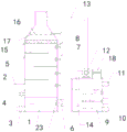
FIG. 1 is a schematic view of the present invention;
FIG. 2 is a partial schematic view showing the connection of the water tank to the air discharge tube;
FIG. 3 is a partial structural view showing the connection of the annular water pipe with a second spray head or the like;
FIG. 4 is a schematic view of a partial axial structure of the tower body connected to a deflector or the like;
wherein: 1. a tower body; 2. an air inlet pipe; 3. a first valve; 4. a second valve; 5. a baffle; 6. a pump body; 7. a water delivery pipe; 8. a first nozzle; 9. a water tank; 10. a third valve; 11. a fourth valve; 12. a fan; 13. a first air pipe; 14. a second air pipe; 15. a filler layer; 16. an annular water pipe; 17. a second nozzle; 18. an exhaust funnel; 19. an activated carbon layer; 20. a stirring paddle; 21. a motor; 22. a water quality monitor; 23. and (4) a filter screen.
Detailed Description
The present invention will be described in further detail with reference to the accompanying drawings and specific embodiments.
A hydrolysis tail gas treatment device is shown in figures 1 to 4 and comprises a tower body 1, an air inlet pipe 2, a first valve 3, a second valve 4, a treatment device, a guide plate 5, a pump body 6, a plurality of groups of first nozzles 8, a packing layer 15, an annular water pipe 16, a plurality of groups of second nozzles 17 and a filter screen 23, wherein the treatment device comprises a water tank 9, a third valve 10, a fourth valve 11, a fan 12, a second air pipe 14, an exhaust funnel 18, an activated carbon layer 19, a stirring paddle 20, a motor 21 and a water quality detector 22.
Be provided with the clear water in the tower body 1, intake pipe 2 and second valve 4 communicate respectively to set up on 1 lateral wall of tower body to intake pipe 2 and second valve 4 all set up above the water level, and 3 intercommunications of first valve set up in 1 bottoms of tower body.
The top end of the tower body 1 is provided with an exhaust port, a plurality of groups of guide plates 5 are respectively installed on the inner side wall of the tower body 1 in a staggered mode, the pump body 6 is installed on the outer side wall of the tower body 1, the input end of the pump body 6 is communicated with the lower portion of the tower body 1, and the filter screen 23 is communicated with the input end of the pump body 6; the output end of the pump body 6 is communicated with a conveying water pipe 7, the input ends of a plurality of groups of first spray heads 8 are communicated with the conveying water pipe 7, and the output ends of a plurality of groups of first spray heads 8 are communicated with the interior of the tower body 1.
9 tops of water tank are provided with the gas vent, third valve 10 intercommunication sets up in 9 bottoms of water tank, fourth valve 11 intercommunication sets up on 9 upper portions of water tank, and the lower part is provided with the clear water in the water tank 9, fan 12 is installed on 9 tops of water tank, fan 12 input intercommunication is provided with first trachea 13, first trachea 13 input and 1 gas vent intercommunication of tower body, second trachea 14 intercommunication sets up on fan 12 output, second trachea 14 output and water tank 9 intercommunication, and the inside clear water that the second trachea 14 output immerges water tank 9.
Packing layer 15 is installed on 1 inside wall upper portion of tower body, and annular water pipe 16 is installed on 1 inside wall upper portion of tower body to annular water pipe 16 sets up in 15 tops of packing layer, carries intercommunication in 7 output of water pipe and the annular water pipe 16, and multiunit second shower nozzle 17 all communicates the setting in 16 outside wall lower parts of annular water pipe.
The 18 intercommunication settings of aiutage 9 exhaust port department in the water tank, activated carbon layer 19 is installed on 18 inside walls of aiutage, 20 right-hand members of stirring rake are rotatory to be installed on 9 inside walls of water tank, motor 21 is installed on 9 lateral walls of water tank, the motor 21 output is connected with 20 right-hand members of stirring rake with one heart, water quality detector 22 sets up on 9 inside walls of water tank, filter screen 23 intercommunication sets up on 6 input ends of the pump body.
The utility model discloses the during operation, the tail gas that condiment processing produced passes through intake pipe 2 and gets into inside 1 tower body, through opening the water extraction of the bottom in the pump body 6 with tower body 1, the water of extraction is carried to the first shower nozzle 8 of multiunit through conveying water pipe 7, thereby spray to inside 1 tower body behind the water atomization through the first shower nozzle 8 of multiunit, the tail gas that gets into in the tower body 1 this moment is S type from up flowing down through 5 water conservancy diversion transports of multiunit guide plate, through the contact of tail gas with the water smoke, make water smoke with tail gas hydrolysis treatment, carry the tail gas water conservancy diversion through setting up multiunit guide plate 5, increase the contact effect of tail gas and water smoke, improve tail gas hydrolysis treatment purifying effect, open fan 12 through the tail gas extraction in first trachea 13 with tower body 1, the tail gas of extraction passes through second trachea 14 and carries to the clear water in the water tank 9, make tail gas and clear water direct mixing, improve the hydrolysis purifying effect of tail gas, later, tail gas passes through the gas of 9 top gas vent outwards discharge, improve the secondary hydrolysis purifying effect of tail gas, reduce the pollution of tail gas to the environment, open more third valve 10 and fourth valve 11 through the cooperation, thereby be convenient to the water drainage in the water tank 9, the operation of water exchange performance in the water tank 9 is improved.
The utility model discloses the main function who realizes does: carry through setting up multiunit guide plate 5 to the tail gas water conservancy diversion, increase the contact effect of tail gas and water smoke, improve tail gas hydrolysis treatment purifying effect, later the tail gas in the tower body 1 is carried to the processing apparatus secondary and is hydrolyzed the purification treatment, reduces the pollution of tail gas to the environment, opens through the cooperation with first valve 3 and second valve 4 to be convenient for discharge the change with the clear water in the tower body 1.
The utility model discloses a pump body 6, fan 12, packing layer 15, motor 21 and water quality testing ware 22 for purchase on the market, this industry technical staff only need according to its subsidiary service instruction install and operate can, and need not the technical staff in this field and pay out creative work.
The foregoing is only a preferred embodiment of the present invention, and it should be noted that, for those skilled in the art, a plurality of modifications and variations can be made without departing from the technical principle of the present invention, and these modifications and variations should also be regarded as the protection scope of the present invention.
Claims (7)
1. The hydrolysis tail gas treatment device comprises a tower body (1), an air inlet pipe (2), a first valve (3) and a second valve (4), clear water is arranged in the tower body (1), the air inlet pipe (2) and the second valve (4) are respectively communicated and arranged on the outer side wall of the tower body (1), the air inlet pipe (2) and the second valve (4) are both arranged above the water level, and the first valve (3) is communicated and arranged at the bottom of the tower body (1); its characterized in that still includes processing apparatus, guide plate (5), the first shower nozzle (8) of the pump body (6) and multiunit, tower body (1) top is provided with the gas vent, gas vent and processing apparatus intercommunication, processing apparatus is used for the secondary hydrolysis to the tail gas and handles, install on tower body (1) inside wall multiunit guide plate (5) position staggered respectively, install on tower body (1) lateral wall pump body (6), pump body (6) input and tower body (1) lower part intercommunication, pump body (6) output intercommunication is provided with delivery pipe (7), intercommunication in first shower nozzle (8) input of multiunit all with delivery pipe (7), communicate with each other in first shower nozzle (8) output of multiunit all with tower body (1).
2. The hydrolysis tail gas treatment device according to claim 1, wherein the treatment device comprises a water tank (9), a third valve (10), a fourth valve (11), a fan (12) and a second air pipe (14), an air outlet is formed in the top end of the water tank (9), the third valve (10) is communicated with the bottom of the water tank (9), the fourth valve (11) is communicated with the upper portion of the water tank (9), clear water is arranged on the inner lower portion of the water tank (9), the fan (12) is installed on the top end of the water tank (9), a first air pipe (13) is communicated with the input end of the fan (12), the input end of the first air pipe (13) is communicated with the air outlet of the tower body (1), the second air pipe (14) is communicated with the output end of the fan (12), the output end of the second air pipe (14) is communicated with the interior of the water tank (9), and the output end of the second air pipe (14) is immersed in the clear water of the water tank (9).
3. The hydrolysis tail gas treatment device according to claim 1, further comprising a packing layer (15), an annular water pipe (16) and a plurality of groups of second spray nozzles (17), wherein the packing layer (15) is installed on the upper portion of the inner side wall of the tower body (1), the annular water pipe (16) is arranged above the packing layer (15), the output end of the conveying water pipe (7) is communicated with the interior of the annular water pipe (16), and the plurality of groups of second spray nozzles (17) are all communicated with the lower portion of the outer side wall of the annular water pipe (16).
4. The hydrolysis tail gas treatment device according to claim 2, further comprising an exhaust funnel (18) and an activated carbon layer (19), wherein the exhaust funnel (18) is communicated with an exhaust port of the water tank (9), and the activated carbon layer (19) is arranged on the inner side wall of the exhaust funnel (18).
5. The hydrolysis tail gas treatment device according to claim 2, further comprising a stirring paddle (20) and a motor (21), wherein the right end of the stirring paddle (20) is rotatably mounted on the inner side wall of the water tank (9), the motor (21) is mounted on the outer side wall of the water tank (9), and the output end of the motor (21) is concentrically connected with the right end of the stirring paddle (20).
6. The hydrolysis tail gas treatment device according to claim 2, further comprising a water quality detector (22), wherein the water quality detector (22) is arranged on the inner side wall of the water tank (9).
7. The hydrolysis tail gas treatment device according to claim 1, further comprising a filter screen (23), wherein the filter screen (23) is communicated with the input end of the pump body (6).
Priority Applications (1)
| Application Number | Priority Date | Filing Date | Title |
|---|---|---|---|
| CN202223295128.4U CN218741029U (en) | 2022-12-08 | 2022-12-08 | Hydrolysis tail gas treatment device |
Applications Claiming Priority (1)
| Application Number | Priority Date | Filing Date | Title |
|---|---|---|---|
| CN202223295128.4U CN218741029U (en) | 2022-12-08 | 2022-12-08 | Hydrolysis tail gas treatment device |
Publications (1)
| Publication Number | Publication Date |
|---|---|
| CN218741029U true CN218741029U (en) | 2023-03-28 |
Family
ID=85682112
Family Applications (1)
| Application Number | Title | Priority Date | Filing Date |
|---|---|---|---|
| CN202223295128.4U Active CN218741029U (en) | 2022-12-08 | 2022-12-08 | Hydrolysis tail gas treatment device |
Country Status (1)
| Country | Link |
|---|---|
| CN (1) | CN218741029U (en) |
-
2022
- 2022-12-08 CN CN202223295128.4U patent/CN218741029U/en active Active
Similar Documents
| Publication | Publication Date | Title |
|---|---|---|
| CN215403456U (en) | Chemical wastewater purification device | |
| CN108404550A (en) | A kind of gas energy-saving purifier of boiler scraped dust granule | |
| CN120420777B (en) | A waste gas treatment device for corrugated paper printing machines | |
| CN110559754A (en) | A flue gas purification and whitening treatment equipment for production and processing in building materials factories | |
| CN218834024U (en) | Granite plate surface treatment dust collector | |
| CN220328239U (en) | Cement plant air dust fall machine | |
| CN210186844U (en) | Packing spraying absorption tower | |
| CN210021636U (en) | Weld cigarette dust collecting equipment | |
| CN217015966U (en) | Pneumatic mixing cyclone tower suitable for flue gas treatment | |
| CN221656223U (en) | Tail gas absorption tower for chemical production | |
| CN219252129U (en) | Waste gas spray treatment device | |
| CN219308366U (en) | Spray washing tower for deodorizing waste gas | |
| CN218307193U (en) | Chemical waste gas treatment device | |
| CN218475104U (en) | Tungsten hexafluoride production spray tower | |
| CN216150364U (en) | Raw material impurity removing device for starch bulking machine | |
| CN210845869U (en) | A kind of desulfurization and dust removal equipment | |
| CN213492883U (en) | Adsorption tower for industrial waste gas treatment | |
| CN211635950U (en) | Coking waste gas processor | |
| CN213492962U (en) | A tail gas spray column for high-efficient haloxyfop original medicine | |
| CN210495711U (en) | A welding fume dedusting equipment | |
| CN210356500U (en) | Integrated energy-saving reconstruction and flue gas treatment flue gas and air device for industrial boiler | |
| CN223474653U (en) | Waste gas treatment device for microbial fertilizer production | |
| CN223351314U (en) | Rotary spraying dust collector | |
| CN221601566U (en) | Environment-friendly dust removal equipment convenient for dust removal | |
| CN222342410U (en) | Multistage waste gas washing tower |
Legal Events
| Date | Code | Title | Description |
|---|---|---|---|
| GR01 | Patent grant | ||
| GR01 | Patent grant |