CN218737612U - Mechanical cipher safe - Google Patents
Mechanical cipher safe Download PDFInfo
- Publication number
- CN218737612U CN218737612U CN202221883918.1U CN202221883918U CN218737612U CN 218737612 U CN218737612 U CN 218737612U CN 202221883918 U CN202221883918 U CN 202221883918U CN 218737612 U CN218737612 U CN 218737612U
- Authority
- CN
- China
- Prior art keywords
- password
- lock
- upper cover
- wheel
- control panel
- Prior art date
- Legal status (The legal status is an assumption and is not a legal conclusion. Google has not performed a legal analysis and makes no representation as to the accuracy of the status listed.)
- Active
Links
- 239000012634 fragment Substances 0.000 claims description 8
- 206010063659 Aversion Diseases 0.000 claims description 3
- 238000009434 installation Methods 0.000 abstract 1
- 230000000694 effects Effects 0.000 description 4
- 239000003814 drug Substances 0.000 description 3
- 229940079593 drug Drugs 0.000 description 2
- 206010019233 Headaches Diseases 0.000 description 1
- 230000015572 biosynthetic process Effects 0.000 description 1
- 230000007547 defect Effects 0.000 description 1
- 238000000151 deposition Methods 0.000 description 1
- 238000010586 diagram Methods 0.000 description 1
- 230000005489 elastic deformation Effects 0.000 description 1
- 231100000869 headache Toxicity 0.000 description 1
- 230000004048 modification Effects 0.000 description 1
- 238000012986 modification Methods 0.000 description 1
- 125000003003 spiro group Chemical group 0.000 description 1
Images


Landscapes
- Lock And Its Accessories (AREA)
Abstract
The utility model discloses a mechanical password safe deposit box, including lock box seat, the upper cover, lock floodgate and password wheelset, lock box seat forms the box structure of upper side open-ended, upper cover one end lateral wall is articulated with a lock box seat end, the upper cover can cover or open the opening of lock box seat, be equipped with the hasp structure on the inside wall of the lock box seat other end, the installation that lock floodgate can slide is in the upper cover, lock floodgate can be connected or the dropout with hasp structure lock, two at least password wheelsets can be rotated install in the upper cover, the upper cover has the structure of windowing that corresponds with the password wheelset, there is coaxial pivoted eccentric wheel on the password wheelset, each eccentric wheel circumference outside surface all tightly supports in lock floodgate surface, the big one section circumference outside surface of eccentric wheel radius on the password wheelset can prevent lock floodgate orientation and hasp structure dropout, the utility model discloses a make things convenient for important article to deposit and take, wholly be pure mechanical structure, it is convenient to go out, need not to use under can being fit for any environment.
Description
Technical Field
The utility model relates to a theftproof technical field especially indicates a mechanical password safe box.
Background
When people go out to travel, people often need to store articles such as car keys, home door lock keys, cards, mobile phones, medicines and the like, at present, people carry the articles with them, and when going out to travel, the articles need to be scattered in a trunk or a bag carried with them, and at present, the storage mode has the following disadvantages:
1. the places where people go out to travel are affected by carrying the articles with the objects, and for some travel occasions where the articles cannot be carried with the objects, the articles need to be additionally stored in a storage place, which is very troublesome;
2. the articles are very important, and when the articles are lost carelessly during traveling, great trouble is brought to people;
3. because the articles are scattered and placed in the luggage or the bag, the articles are often required to be turned over when being used, and the turning over is time-consuming, labor-consuming and easy to damage.
Therefore, when people go out to travel, how to keep the important articles properly becomes a problem of headache.
SUMMERY OF THE UTILITY MODEL
In order to overcome the defects, the utility model provides a mechanical password safe box, this mechanical password safe box simple structure, can deposit the important article of hand-carrying safely, avoid losing, still need not the power consumption, ensure the normal use of going out.
The utility model discloses a solve the technical scheme that its technical problem adopted: the mechanical password safe deposit box comprises a lock box base, an upper cover, a lock gate and password wheel sets, wherein the lock box base is of a box-shaped structure with an upper opening, one side wall of one end of the upper cover is hinged to one side wall of one end of the lock box base, the upper cover can cover or open an opening of the lock box base by overturning around a hinge shaft, a lock structure is arranged on the inner side wall of the other end of the lock box base, the lock gate can be installed on the inner side of the upper cover in a sliding mode with a set distance, the lock gate can be fixedly connected with or disengaged from the lock structure on the inner side wall of the lock box base in a sliding mode, at least two password wheel sets can be installed on the inner side of the upper cover in a rotating mode, window disengaging structures corresponding to the password wheel sets one by one are formed on the upper cover, password marks uniformly distributed on the circumference outer side walls of the password wheels can be exposed out of the outer side of the upper cover through the window disengaging structures of the upper cover, coaxial rotating eccentric wheels are formed on the password wheel sets, the circumference outer side surfaces of the eccentric wheels on the password wheel sets are tightly abutted to one side surfaces of the lock gate moving towards the lock gate and the lock gate structure disengaging directions, and the eccentric wheels, and one section of the eccentric wheels with large radius can be prevented from moving towards the eccentric wheels.
As a further improvement, the upper cover is internally provided with a reset elastic part which provides elastic holding force for the lock brake to move towards the direction of the lock structure lock.
As a further improvement, be equipped with spring slot on the lock floodgate, elastic component one end that resets is inserted and is located in the spring slot, and elastic component one end that resets tightly supports on the spring slot bottom surface, be equipped with spring backstop convex surface on the upper cover inside wall, the elastic component other end that resets tightly supports on the spring backstop convex surface of upper cover.
As the utility model discloses a further improvement, be equipped with on the lock floodgate along its slip direction's rectangular hole, on cover be equipped with the just right screw hole in rectangular hole, the threaded hole internal spiro union of upper cover has connecting screw, on connecting screw can relative slip insert locate the rectangular hole of lock floodgate, and the connecting screw head stops in lock floodgate screw hole side surface dorsad.
As the utility model discloses a further improvement still is equipped with the control panel, the control panel can be in installing of certain limit internal motion in the upper cover, and the control panel tightly supports the lateral wall surface of lock brake orientation direction of unblanking motion along the one end of the direction of its motion, and the control panel tightly supports on the eccentric wheel circumference lateral surface of all password wheelsets along the other end of its direction of motion.
As the utility model discloses a further improvement, control panel one end is installed on covering, and the control panel other end can be relative rather than one end swing settlement angle, the lock floodgate is equipped with the hole of keeping away of indent on the lateral wall surface of direction motion of unblanking, and the control panel other end swing realize with the lock floodgate towards the lateral wall surface of direction motion of unblanking or keep away the hole on its surface just right, and the control panel is followed the lateral wall elasticity of its direction of swing and is tightly supported on the eccentric wheel circumference outside on all password wheelsets on the surface.
As a further improvement, control panel one end is articulated to be located and to cover, still is equipped with the control panel elastic component that resets, control panel elastic component both ends that reset tightly support the eccentric wheel side surface of upper cover inside wall or control panel dorsad password wheelset respectively.
As a further improvement, the lock catch structure on the inner side wall of the lock box base is an inward concave slot or a boss protruding from the edge of the side wall of the opening of the lock box base, the lock gate can be slid along the direction of depth of the inward concave slot or the direction of extension of the boss, one end of the lock gate is provided with a lock tongue, the lock tongue can be inserted into the inward concave slot and stopped on the inner side wall of the inward concave slot or on the boss lower side and stopped on the boss.
As a further improvement, the spring bolt is inclined plane or cambered surface structure along the both sides wall of upper cover rotation direction, and the upper cover outside still is equipped with the T shape groove structure that an opening size is less than inside size on the surface, T shape groove structure just right with the password wheelset, and the structure of windowing that covers on is located this T shape groove structure bottom surface, be formed with sunken spout on the T shape groove structure opening lateral wall, can the gliding password apron of installing in the spout, the password apron can be followed the spout and slided and open or be closed with T shape groove structure opening, forms the pull handle structure that supplies the people to hand pulling on this password apron.
As a further improvement, the password wheel group includes dabber, interior password wheel, outer password wheel, password elastic component, password number modulation spare and password wheel location shell fragment, install in the upper cover that dabber axial can slide the settlement distance, dabber one end circumference lateral wall is equipped with the fender ring of a radial evagination, password number modulation spare one end stretches out in the upper cover outside, the dabber one end outside is located to password number modulation spare other pot head, and the backstop is in fender ring one end terminal surface, the dabber outside is located to two at least interior password wheel sequence covers, interior password wheel forms the stair structure that one end diameter is less than other end diameter, the one end that its diameter is big forms the eccentric wheel, be formed with one section spline structure on the little one end circumference lateral wall root of its diameter, the one end outside that interior password wheel diameter is little is located to the cover of outer password wheel one-to-one, and outer password wheel inboard is formed with the keyway that inner password wheel spline structure matches, each interior password wheel axial sequence in close contact with the dabber and finally support on the fender ring other end terminal surface of one end, the elastic component cover locates the other end outside, the elastic component cover is located the password wheel inside wall and the password wheel location shell fragment outside respectively, the other end outside.
The utility model has the advantages that: the utility model discloses an upper cover covers on lock box seat, supply to form a confined space with lock box seat and be used for having the key, the card, the cell-phone, important article such as medicine, these article have been avoided scattering in case and bag, be convenient for take, the upper cover carries out the lock with lock box seat through lock floodgate and hasp structure and is connected, set up and input password through the password wheelset, realize lock box seat and upper cover locking and unblank, the security of depositing of this kind of important article has been improved, avoid being stolen, and it conveniently hand-carries or fixes at the assigned position, make things convenient for important article to deposit and take, this password safe deposit box is whole to be pure mechanical structure, go out convenient to carry, need not the power consumption, can be fit for using under any environment.
Drawings
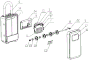
Fig. 1 is an exploded perspective view of the present invention;
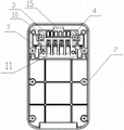
FIG. 2 is a front view of the upper cover of the present invention;
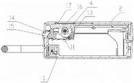
FIG. 3 is a cross-sectional view of the present invention in a locked state;
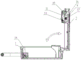
FIG. 4 is a sectional view showing the uncapped state of the present invention;
FIG. 5 is a schematic view of the control panel of the present invention in an unlocked state;
fig. 6 is a schematic diagram of the present invention showing the control panel in a locked state.
Detailed Description
The embodiment is as follows: a mechanical password safe deposit box comprises a lock box base 1, an upper cover 2, a lock gate 3 and password wheel sets 4, wherein the lock box base 1 is formed into a box-shaped structure with an opening at the upper side, the side wall at one end of the upper cover 2 is hinged with the side wall at one end of the lock box base 1, the upper cover 2 can cover or open the opening of the lock box base 1 by turning around a hinge shaft, a lock catch structure 14 is arranged on the inner side wall at the other end of the lock box base 1, the lock gate 3 can be installed at the inner side of the upper cover 2 in a sliding way with a set distance, the lock gate 3 can be fixedly connected or disconnected with the lock catch structure 14 on the inner side wall of the lock box base 1 in a sliding way, at least two password wheel sets 4 can be installed at the inner side of the upper cover 2 in a rotating way, the window structure that is formed with on the upper cover 2 with each 4 one-to-one of password wheelset, evenly distributed's password sign can expose in the upper cover 2 outside through the window structure of upper cover 2 on the circumference lateral wall on the password wheel, be formed with coaxial pivoted eccentric wheel on the password wheelset 4, the eccentric wheel circumference outside surface on each password wheelset 4 all tightly supports in the side surface of lock brake 3 orientation and the motion of hasp structure 14 dropout direction, and the big one section circumference outside surface of eccentric wheel radius on the password wheelset 4 can prevent lock brake 3 orientation and the motion of hasp structure 14 dropout direction.
When the upper cover 2 covers the opening slot structure opening of the lock box base 1, a closed article storage space is formed between the opening slot structure of the lock box base 1 and the upper cover 2 and is used for placing articles such as car keys, home door lock keys, cards, mobile phones, medicines and the like, after the articles are placed, the upper cover 2 covers the opening of the lock box base 1, the eccentric wheel structure on the cipher wheel group 4 rotates along with the cipher wheel group 4 by rotating the cipher wheel group 4, the position with large radius of the eccentric wheel structure on at least one cipher wheel group 4 is contacted with the lock brake 3, the lock brake 3 slides forwards and is buckled and fixedly connected with the lock catch structure 14 on the side wall of the opening slot structure of the lock box base 1, the upper cover 2 is fixedly connected and positioned with the lock box base 1, when the lock is required to be unlocked, only the cipher wheel group 4 needs to be rotated, so that the cipher mark of the cipher wheel group 4 exposed through the opening structure is correct, the position with small radius of the eccentric wheel structure of the password wheel group 4 is contacted with the lock brake 3, so that the lock brake 3 can slide reversely, and further is separated from the lock catch structure 14 on the side wall of the open slot structure of the lock box base 1, so as to realize unlocking, at the moment, the upper cover 2 can be opened, and the articles in the lock box base 1 can be taken, the lock box base 1 can also be provided with a hanging buckle 6 hung on the clothes of people or the case, so as to be convenient for carrying, one side wall of the lock box base 1 is optimally formed with an L-shaped structure, one side wall of the upper cover 2 is stopped on the two side walls of the L-shaped structure, the structure can realize the limitation of the opening angle of the upper cover 2, so that the upper cover 2 can be opened and closed within the range of 90 degrees, the damage caused by the overlarge opening and the articles in the box can be prevented from falling off, the upper cover 2 can be made into an integral structure or a split structure, for example, the cover plate 5 is fixedly assembled with the bracket 24 with the groove, and a space for containing the lock brake 3 and the password wheel group 4 is formed between the two, this kind of structure makes things convenient for the equipment of lock floodgate 3 and password wheelset 4 more, simultaneously, hides the space of protection formation between apron and support with lock floodgate 3 and password wheelset 4 in, prevents to damage.
The upper cover 2 is also provided with a reset elastic piece 7, and the reset elastic piece 7 provides elastic retaining force for the locking brake 3 to move towards the buckling direction of the locking structure 14. The elastic component 7 that resets makes upper cover 2 cover lock box seat 1 opening on the back, and lock brake 3 is in the same place with the hasp structure 14 lock on the lock box seat 1 automatically under the elastic force effect, avoids the user to forget to operate lock brake 3 and leads to upper cover 2 and lock box seat 1 to carry out the lock failure, simultaneously, avoids the password to open the back, and upper cover 2 and lock box seat 1 stand the horse to be opened, leads to the interior article of lock box seat 1 to fall out, leads to losing or damaging.
The lock brake 3 is provided with a spring slot 8, one end of the reset elastic piece 7 is inserted into the spring slot 8, one end of the reset elastic piece 7 tightly abuts against the bottom surface of the spring slot 8, the inner side wall of the upper cover 2 is provided with a spring stop convex surface 9, and the other end of the reset elastic piece 7 tightly abuts against the spring stop convex surface 9 on the upper cover 2. Through set up spring slot 8 on lock floodgate 3, realize the direction of the elastic deformation direction of elastic component 7 that resets to and reset the support of elastic component 7 and press the location, the elastic component 7 that resets is the spring best, also can be for elasticity cushion or shell fragment etc..
The lock brake 3 is provided with a long hole 10 along the sliding direction, the upper cover 2 is provided with a threaded hole right opposite to the long hole 10, a connecting screw is screwed in the threaded hole of the upper cover 2, the connecting screw can be inserted into the long hole 10 of the lock brake 3 in a relative sliding mode, and the head of the connecting screw is stopped on one side surface, opposite to the threaded hole, of the lock brake 3. The limit of the sliding distance of the lock brake 3 and the guide of the sliding direction of the lock brake 3 are realized by the connection screw sliding in the long hole 10 of the lock brake 3.
The anti-theft lock is characterized in that a control plate 11 is further arranged, the control plate 11 can be installed in the upper cover 2 in a certain range in a moving mode, one end of the control plate 11 in the moving direction tightly abuts against the surface of the side wall of the lock brake 3 moving towards the unlocking direction, and the other end of the control plate 11 in the moving direction tightly abuts against the outer side face of the circumference of the eccentric wheel of all the password wheel sets 4. Because the other end of the control panel 11 is tightly propped against the outer side surfaces of the circumferences of the eccentric wheels of all the password wheel sets 4, only when all the eccentric wheels are the outer circular surfaces with small radiuses and are contacted with the other end of the control panel 11, one end of the control panel 11 is in an unlocking position, and unlocking is realized.
The lock catch structure 14 on the inner side wall of the lock box base 1 is an inward concave slot or a boss protruding from the edge of the opening side wall of the lock box base 1, the lock gate 3 can slide along the depth direction of the inward concave slot or the extension direction of the boss, a lock tongue 15 is arranged at one end of the lock gate 3, the lock tongue 15 can be inserted into the inward concave slot and stopped on the upper side wall of the inward concave slot or on the lower side of the boss and stopped on the boss. The locking is realized through the grafting, simple structure, and the dropout is convenient, and in addition, hasp structure 14 also can realize the lock with lock brake 3 through the mode that the latch hook catches on and be connected, and this kind is the equivalent alternative structure that this kind of technical personnel in the field thought very easily according to this patent, belongs to this patent protection scope.
The utility model discloses a password lock bolt, including lock tongue 15, password apron 17, the both sides wall of upper cover 2 direction of rotation is inclined plane or cambered surface structure, and 2 outside surfaces of upper cover still are equipped with an opening size and are less than the T shape groove structure 16 of inside dimension on the surface, T shape groove structure 16 just right with password wheelset 4, and the structure of windowing on the upper cover 2 is located this T shape groove structure 16 bottom surfaces, be formed with sunken spout on the 16 opening lateral walls of T shape groove structure, can be gliding in the spout installs password apron 17, password apron 17 can slide along the spout and open or be closed with T shape groove structure 16 openings, forms the pull handle structure that supplies the staff to stimulate on this password apron 17. Through designing into inclined plane or cambered surface with spring bolt 15 edge, form and unblank and the shutting direction, when guaranteeing that upper cover 2 covers on lock box seat 1 opening, and when uncapping, spring bolt 15 of lock floodgate 3 can let automatically realize and lock box seat 1 on 14 tripping of hasp structures, password apron 17 can cover password wheelset 4, play dirt-proof effect, realize password wheelset 4 hidden effect simultaneously, make the surface of whole upper cover 2 one side of lock box seat 1 dorsad level and smooth, pleasing to the eye.
The password wheel set 4 comprises a mandrel 18, an inner password wheel 19, an outer password wheel 20, a password elastic part 21, a password number adjusting part 22 and a password wheel positioning elastic sheet 23, the mandrel 18 is axially installed in the upper cover 2 in a sliding way with a set distance, a retaining ring which is protruded outwards in the radial direction is arranged on the circumferential outer side wall at one end of the mandrel 18, one end of the password number adjusting part 22 extends out of the upper cover 2, the other end of the password number adjusting part 22 is sleeved outside one end of the mandrel 18 and is stopped at the end surface at one end of the retaining ring, at least two inner password wheels 19 are sequentially sleeved outside the mandrel 18, the inner password wheel 19 forms a step structure with one end having a diameter smaller than that of the other end, the end having a large diameter forms an eccentric wheel, and the root of the circumferential outer side wall at one end having a small diameter forms a spline structure, the one-to-one cover of outer password wheel 20 locates the one end outside that interior password wheel 19 diameter is little, and outer password wheel 20 inboard is formed with the keyway that matches with the spline structure on the interior password wheel 19, 19 axial order in close contact with of each interior password wheel finally tightly support on the fender ring other end terminal surface of dabber 18 one end, 18 other end outsides of dabber are located to password elastic component 21 cover, password elastic component 21 both ends tightly support 2 inside walls of upper cover and lie in on the interior password wheel 19 other end terminal surface of the dabber 18 other end respectively, password wheel location shell fragment 23 one end fixed mounting is in the inner cup inboard, the password wheel location shell fragment 23 other end tightly supports with each outer password wheel 20 circumference outside surface elasticity. The password wheel group 4 can realize password modification through the password number adjusting part 22, and the use safety is improved.
Claims (10)
1. A mechanical password safe deposit box, characterized by: the anti-theft lock comprises a lock box base (1), an upper cover (2), a lock gate (3) and password wheel sets (4), wherein the lock box base is of a box-shaped structure with an upper opening, one end side wall of the upper cover is hinged to one end side wall of the lock box base, the upper cover can cover or open the opening of the lock box base by overturning around a hinged shaft, a lock catch structure (14) is arranged on the inner side wall of the other end of the lock box base, the lock gate can be installed on the inner side of the upper cover in a sliding mode with a set distance, the lock gate can be fixedly connected with or disengaged from the lock catch structure on the inner side wall of the lock box base in a buckling mode, at least two password wheel sets can be installed on the inner side of the upper cover in a rotating mode, window opening structures corresponding to the password wheel sets one by one are formed on the upper cover, password marks uniformly distributed on the outer side wall of the circumference of the password wheel sets can be exposed out of the outer side of the upper cover through the window opening structures of the upper cover, coaxial rotating eccentric wheels are formed on the password wheel sets, the outer side surfaces of the circumference of the eccentric wheels on each password wheel set are tightly abutted to one side surface of the lock gate moving towards the lock gate and the lock catch structure in a tripping direction of the lock gate.
2. The mechanical password safe of claim 1, wherein: and a reset elastic piece (7) is also arranged in the upper cover and provides elastic retaining force for the locking brake to move towards the buckling direction of the locking structure.
3. The mechanical password safe of claim 2, wherein: the lock brake is provided with a spring slot (8), one end of the reset elastic piece is inserted into the spring slot, one end of the reset elastic piece tightly abuts against the bottom surface of the spring slot, the inner side wall of the upper cover is provided with a spring stop convex surface (9), and the other end of the reset elastic piece tightly abuts against the spring stop convex surface on the upper cover.
4. The mechanical password safe deposit box of claim 1, 2, or 3, wherein: the lock brake is provided with a long hole (10) along the sliding direction of the lock brake, a threaded hole right opposite to the long hole is formed in the upper cover, a connecting screw is screwed in the threaded hole of the upper cover, the connecting screw can be inserted into the long hole of the lock brake in a relative sliding mode, and the head of the connecting screw is stopped on one side surface, back to the threaded hole, of the lock brake.
5. A mechanical password safe deposit box according to claim 1 or 2, characterized in that: the anti-theft device is characterized in that a control panel (11) is further arranged, the control panel can be installed in the upper cover in a certain range to move, one end of the control panel in the moving direction tightly supports the surface of the side wall of the locking brake moving towards the unlocking direction, and the other end of the control panel in the moving direction tightly supports the outer side faces of the circumferences of the eccentric wheels of all the password wheel sets.
6. The mechanical password safe of claim 5, wherein: control panel one end is installed on covering, and the control panel other end can be relative rather than one end swing set angle, be equipped with the aversion hole (12) of indent on the lateral wall surface that the lock floodgate moved towards the direction of unblanking, the control panel other end swing realize with the lock floodgate towards the lateral wall surface of the direction of unblanking motion or keep away the hole on its surface just right, the control panel along its swing direction's lateral wall elasticity tightly support on all the eccentric wheel circumference outside surfaces on the wheelset.
7. The mechanical password safe of claim 5, wherein: one end of the control panel is hinged to the upper cover, and the control panel reset elastic piece (13) is further arranged, and two ends of the control panel reset elastic piece respectively tightly abut against the inner side wall of the upper cover or the surface of one side of the eccentric wheel of the control panel, which faces away from the password wheel set.
8. A mechanical password safe deposit box according to claim 1 or 2, characterized in that: the lock catch structure on the inner side wall of the lock box base is an inward concave slot or a boss protruding from the edge of the side wall of the opening of the lock box base, the lock brake can slide along the depth direction of the inward concave slot or the extension direction of the boss, a lock tongue (15) is arranged at one end of the lock brake, and the lock tongue can be inserted into the inward concave slot and stopped on the upper side wall of the inward concave slot or on the lower side of the boss and stopped on the boss.
9. A mechanical password safe according to claim 8, wherein: the utility model discloses a password lock bolt, including lock tongue, password apron, spout, password apron, the lock tongue is for inclined plane or cambered surface structure along the both sides wall of upper cover direction of rotation, and the upper cover outside still is equipped with an opening size on the surface and is less than inside size's T shape groove structure (16), T shape groove structure just right with the password wheelset, and the structure of windowing of upper cover is located this T shape groove structure bottom surface, be formed with sunken spout on the T shape groove structure opening lateral wall, can gliding password apron (17) of installing in the spout, password apron can slide along the spout and open or be closed with T shape groove structure opening, forms the pull handle structure that supplies the staff to stimulate on this password apron.
10. The mechanical password safe of claim 1, wherein: the password wheel set comprises a mandrel (18), an inner password wheel (19), an outer password wheel (20), a password elastic part (21), a password number adjusting part (22) and a password wheel positioning elastic sheet (23), the mandrel is axially installed in an upper cover in a sliding manner with a set distance, a retaining ring which is radially protruded outwards is arranged on the outer side wall of the circumference at one end of the mandrel, one end of the password number adjusting part extends out of the outer side of the upper cover, the other end of the password number adjusting part is sleeved outside one end of the mandrel and is stopped at the end surface at one end of the retaining ring, at least two inner password wheels are sequentially sleeved outside the mandrel, the inner password wheels form a step structure with one end diameter smaller than that of the other end, and the end with a large diameter forms an eccentric wheel, the one end circumference lateral wall root that its diameter is little is formed with one section spline structure on, the one end outside that interior password wheel diameter is little is located to the cover of outer password wheel one-to-one, and outer password wheel inboard is formed with the keyway that matches with interior password wheel on spline structure, each interior password wheel axial order in close contact with and finally tightly support on the fender ring other end terminal surface of dabber one end, the dabber other end outside is located to the password elastic component cover, the password elastic component both ends tightly support the upper cover inside wall respectively and lie in on the interior password wheel other end terminal surface of the dabber other end, password wheel location shell fragment one end fixed mounting is inboard in the inner cup, the password wheel location shell fragment other end tightly supports with each outer password wheel circumference outside surface elasticity.
Priority Applications (1)
| Application Number | Priority Date | Filing Date | Title |
|---|---|---|---|
| CN202221883918.1U CN218737612U (en) | 2022-07-21 | 2022-07-21 | Mechanical cipher safe |
Applications Claiming Priority (1)
| Application Number | Priority Date | Filing Date | Title |
|---|---|---|---|
| CN202221883918.1U CN218737612U (en) | 2022-07-21 | 2022-07-21 | Mechanical cipher safe |
Publications (1)
| Publication Number | Publication Date |
|---|---|
| CN218737612U true CN218737612U (en) | 2023-03-28 |
Family
ID=85690503
Family Applications (1)
| Application Number | Title | Priority Date | Filing Date |
|---|---|---|---|
| CN202221883918.1U Active CN218737612U (en) | 2022-07-21 | 2022-07-21 | Mechanical cipher safe |
Country Status (1)
| Country | Link |
|---|---|
| CN (1) | CN218737612U (en) |
Cited By (1)
| Publication number | Priority date | Publication date | Assignee | Title |
|---|---|---|---|---|
| CN115177085A (en) * | 2022-07-21 | 2022-10-14 | 苏州琨山智能科技有限公司 | Mechanical cipher safe |
-
2022
- 2022-07-21 CN CN202221883918.1U patent/CN218737612U/en active Active
Cited By (1)
| Publication number | Priority date | Publication date | Assignee | Title |
|---|---|---|---|---|
| CN115177085A (en) * | 2022-07-21 | 2022-10-14 | 苏州琨山智能科技有限公司 | Mechanical cipher safe |
Similar Documents
| Publication | Publication Date | Title |
|---|---|---|
| US8910498B2 (en) | Lockout cabinet | |
| TWM265430U (en) | Storage apparatus for safety check media of lock | |
| CN114562176B (en) | Smart safe | |
| TWM267899U (en) | Depositing apparatus of suitcase security checking medium | |
| US20180142497A1 (en) | Door lock | |
| GB2037257A (en) | Safe | |
| US2941837A (en) | Package receiver for automobiles | |
| US12264509B1 (en) | Merchandise anti-theft device with a quick-release mechanism | |
| CN206031601U (en) | Motorcycle rear box | |
| CN213710693U (en) | One-key release anti-theft protection direct-locking device of luggage case | |
| CN219891610U (en) | Computer safety anti-theft box | |
| CN115177085A (en) | Mechanical cipher safe | |
| CN218484180U (en) | Vertical display cabinet | |
| CN220979137U (en) | Intelligent invisible drawer lock | |
| GB2058196A (en) | A Casket and its Lock Device | |
| JP3197691U (en) | Locking device with unlocking button | |
| CN220645632U (en) | Safe deposit box convenient to take and put | |
| CN201062456Y (en) | Drawing-button of theft protection installation for railway signal transformer box | |
| CN111642906B (en) | Anti-theft detection mechanism of scheme storage device for city planning | |
| US2163042A (en) | Container closure | |
| CN202611369U (en) | Key cover mounting structure for combination lock | |
| CN215873727U (en) | Intelligent anti-loss and anti-theft computer bag | |
| CN207457321U (en) | A kind of electrical energy metering tank | |
| US1459375A (en) | Safety receptacle for bottles and the like | |
| CN202073403U (en) | Lock head for oil tank cover |
Legal Events
| Date | Code | Title | Description |
|---|---|---|---|
| GR01 | Patent grant | ||
| GR01 | Patent grant |