CN218735595U - Security protection light current network control cabinet - Google Patents

Security protection light current network control cabinet Download PDF

Info

Publication number
CN218735595U
CN218735595U CN202222478542.2U CN202222478542U CN218735595U CN 218735595 U CN218735595 U CN 218735595U CN 202222478542 U CN202222478542 U CN 202222478542U CN 218735595 U CN218735595 U CN 218735595U
Authority
CN
China
Prior art keywords
cabinet body
mounting panel
network control
cabinet
current network
Prior art date
Legal status (The legal status is an assumption and is not a legal conclusion. Google has not performed a legal analysis and makes no representation as to the accuracy of the status listed.)
Active
Application number
CN202222478542.2U
Other languages
Chinese (zh)
Inventor
周柱
Current Assignee (The listed assignees may be inaccurate. Google has not performed a legal analysis and makes no representation or warranty as to the accuracy of the list.)
Guizhou Yishun Communication Construction Engineering Co.,Ltd.
Original Assignee
Yancheng Fuyin Information Technology Co ltd
Priority date (The priority date is an assumption and is not a legal conclusion. Google has not performed a legal analysis and makes no representation as to the accuracy of the date listed.)
Filing date
Publication date
Application filed by Yancheng Fuyin Information Technology Co ltd filed Critical Yancheng Fuyin Information Technology Co ltd
Priority to CN202222478542.2U priority Critical patent/CN218735595U/en
Application granted granted Critical
Publication of CN218735595U publication Critical patent/CN218735595U/en
Active legal-status Critical Current
Anticipated expiration legal-status Critical

Links

Images

Landscapes

  • Casings For Electric Apparatus (AREA)

Abstract

The utility model discloses a security protection weak current network control cabinet, which comprises a cabinet body, wherein the inner walls of the two sides of the upper end and the lower end of the cabinet body are both provided with a limiting groove, the front of the cabinet body is hinged with a cabinet door, and the cabinet body is internally provided with an installation mechanism; installation mechanism includes the mounting panel, and the equal sliding connection of mounting panel is in the inside of the cabinet body, and the both sides of mounting panel all are connected with the commentaries on classics board through the pivot rotation, and the equal fixedly connected with fixed plate of back lower extreme of two commentaries on classics boards all pegs graft on two fixed plates has the picture peg, the beneficial effects of the utility model are that: the utility model discloses a set up a mobilizable installation mechanism in the inside of the cabinet body, installation mechanism's mounting panel sliding connection is in the inside of the cabinet body, and the internal electronic parts of cabinet is fixed on installation mechanism's mounting panel, and the staff can pull out the mounting panel from the inside of the cabinet body when overhauing, enlarges the operating space when overhauing, makes things convenient for light to illuminate the electronic parts periphery that overhauls simultaneously, has made things convenient for staff's maintenance work.

Description

Security protection light current network control cabinet
Technical Field
The utility model relates to a switch board technical field specifically is a security protection light current network control cabinet.
Background
The network control cabinet is also called a network cabinet, is used for combining and installing a panel, a plug-in box, an electronic component, a device, a mechanical part and a component to form an integral installation box, generally has a cuboid shape, is placed on the ground, provides adaptive environment and safety protection for normal work of electronic equipment, is also one of hardware components of a security weak current system, and can be convenient for workers to control other equipment of the security weak current system during use.
The network control cabinet of the weak current system of present security protection is when using, various electronic parts are fixed on the inner wall of switch board mostly, therefore the staff is when examining and repairing the electronic parts in the switch board, open the cabinet door mostly, stretch the inside of switch board with the hand and examine and repair the operation, and the space in the switch board is most less, and light is darker, when examining and repairing, the staff is difficult to see clearly the periphery of examining and repairing the electronic parts, action when the staff overhauls simultaneously is too big, just can strike on the inner wall of switch board, or on peripheral other electronic parts, cause the damage, inconvenient maintenance.
SUMMERY OF THE UTILITY MODEL
An object of the utility model is to provide a security protection light current network switch board to solve the problem that proposes among the above-mentioned background art.
In order to achieve the above object, the utility model provides a following technical scheme: a security protection weak current network control cabinet comprises a cabinet body, wherein limiting grooves are formed in the inner walls of two sides of the upper end and the lower end of the cabinet body, a cabinet door is hinged to the front of the cabinet body, and an installation mechanism is installed inside the cabinet body;
installation mechanism includes the mounting panel, the equal sliding connection of mounting panel is in the inside of the cabinet body, the both sides of mounting panel all are rotated through the pivot and are connected with the commentaries on classics board, two the equal fixedly connected with fixed plate of back lower extreme of commentaries on classics board, two all peg graft on the fixed plate and have the picture peg.
Preferably, a plurality of radiating holes are formed in the side walls of the two sides of the cabinet body, and the radiating holes in the two sides of the cabinet body are identical in number and correspond to one another.
Preferably, equal fixedly connected with stopper on the back outer wall of lower extreme both sides on the mounting panel, the equal sliding connection of stopper is in the inside of homonymy spacing groove.
Preferably, one side of the rotating plates far away from the cabinet body is abutted to the inner wall of the cabinet body, and the middle parts of the rotating plates close to one side are provided with pull grooves.
Preferably, the two insertion plates are both in an L-shaped structure, and the horizontal parts of the two insertion plates are longer than the fixed plate at the same side of the rotating plate.
Preferably, the upper and lower end outer wall of mounting panel all supports on the inner wall of the cabinet body, the distance between the side all is the same with the distance between the side around the cabinet body is inside about the lower extreme on the mounting panel.
Compared with the prior art, the beneficial effects of the utility model are that: the utility model discloses a set up a mobilizable installation mechanism in the inside of the cabinet body, installation mechanism's mounting panel sliding connection is in the inside of the cabinet body, and the internal electronic parts of cabinet is fixed on installation mechanism's mounting panel, and the staff can pull out the mounting panel from the inside of the cabinet body when overhauing, enlarges the operating space when overhauing, makes things convenient for light to illuminate the electronic parts periphery that overhauls simultaneously, has made things convenient for staff's maintenance work.
Drawings
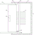
FIG. 1 is a front sectional structure diagram of the present invention;
FIG. 2 is a schematic side sectional structure view of the present invention installed in the cabinet body;
FIG. 3 is a schematic view of the present invention when it is deployed;
FIG. 4 is a schematic view of the connection structure of the inserting plate and the fixing plate of the present invention;
fig. 5 is a schematic view of the external structure of the present invention when closed.
In the figure: 1. a cabinet body; 2. a limiting groove; 3. an installation mechanism; 31. mounting a plate; 32. a limiting block; 33. a rotating shaft; 34. rotating the plate; 35. groove drawing; 36. a fixing plate; 37. inserting plates; 4. a cabinet door; 5. and (4) heat dissipation holes.
Detailed Description
The technical solutions in the embodiments of the present invention will be described clearly and completely with reference to the accompanying drawings in the embodiments of the present invention, and it is obvious that the described embodiments are only some embodiments of the present invention, not all embodiments. Based on the embodiments in the present invention, all other embodiments obtained by a person skilled in the art without creative work belong to the protection scope of the present invention.
Referring to fig. 1-5, the present invention provides a technical solution: a security protection weak current network control cabinet comprises a cabinet body 1, wherein limiting grooves 2 are formed in the inner walls of two sides of the upper end and the lower end of the cabinet body 1, a cabinet door 4 is hinged to the front side of the cabinet body 1, and an installation mechanism 3 is installed inside the cabinet body 1; installation mechanism 3 includes mounting panel 31, and the equal sliding connection of mounting panel 31 is in the inside of the cabinet body 1, and the both sides of mounting panel 31 all rotate through pivot 33 and are connected with commentaries on classics board 34, and the equal fixedly connected with fixed plate 36 of back lower extreme of two commentaries on classics boards 34 has all pegged graft on two fixed plates 36 and has picture peg 37, can fix electronic parts on mounting panel 31 during the use, can pull out the cabinet body 1 with electronic parts when overhauing, convenient maintenance work.
Two picture peg 37 all are L shape structure, and the length of two picture peg 37 horizontal part distance homonymy commentaries on classics board 34 all is longer than the length of place fixed plate 36, plug picture peg 37 when convenient to use, the upper and lower end outer wall of mounting panel 31 all supports on the inner wall of cabinet body 1, distance between the side all is the same with the distance between the side around cabinet body 1 inside about the mounting panel 31 is last lower extreme front and back, avoid mounting panel 31 to rock in cabinet body 1's inside, a plurality of louvres 5 have all been seted up on the lateral wall of cabinet body 1's both sides, louvre 5 quantity the same and the one-to-one of cabinet body 1 both sides, be convenient for dispel the heat in the cabinet body 1, all fixedly connected with stopper 32 on the back outer wall of mounting panel 31 upper and lower extreme both sides, stopper 32 all sliding connection is in homonymy spacing groove 2's inside, can descend mounting panel 31 and fix in cabinet body 1's inside in the circumstances that does not influence mounting panel 31 is gliding, one side is kept away from mutually for two commentaries on board 34 all supports on cabinet body 1's inner wall, pull groove 35 has all been seted up to two commentaries on one side mutually, the middle part of two commentaries on one side of commentaries on board 34 is close to fix the front of cabinet body 31 outside when being convenient to overhaul, fix the cabinet body 1 simultaneously, the position of maintaining, change board 34.
Specifically, use the utility model discloses the time, fix electronic parts on mounting panel 31, and pull out cabinet body 1 with the wire on the electronic parts, link together with other equipment, the equipment that electronic parts control on the staff accessible mounting panel 31 is connected, when the staff overhauls the electronic parts on the mounting panel 31, expand two cabinet doors 4, and lean on in the positive side of cabinet body 1, grasp commentaries on classics board 34, stimulate mounting panel 31 forward through commentaries on classics board 34, pull out cabinet body 1 with mounting panel 31's front, then rotate commentaries on classics board 34, support commentaries on classics board 34 on cabinet door 4, extrude picture peg 37 again, insert picture peg 37 on mounting panel 31 lower extreme inner wall, fix the position of commentaries on classics board 34, make mounting panel 31 unable in cabinet body 1 slide, then the staff can overhaul the electronic parts on the mounting panel 31, after the maintenance, extract picture peg 37 again, and change commentaries on classics board 34 back original position, and push back the inside of cabinet body 1 with mounting panel 31, it can to close cabinet door 4.
In the description of the present invention, it is to be understood that the terms "coaxial", "bottom", "one end", "top", "middle", "other end", "upper", "one side", "top", "inner", "front", "center", "both ends", and the like, indicate orientations or positional relationships based on the orientations or positional relationships shown in the drawings, and are only for convenience of description and simplicity of description, and do not indicate or imply that the device or element referred to must have a particular orientation, be constructed and operated in a particular orientation, and therefore, should not be construed as limiting the present invention.
Furthermore, the terms "first", "second", "third", "fourth" are used for descriptive purposes only and are not to be construed as indicating or implying a relative importance or implicitly indicating the number of technical features indicated, whereby the features defined as "first", "second", "third", "fourth" may explicitly or implicitly include at least one such feature.
In the present invention, unless otherwise expressly stated or limited, the terms "mounted," "disposed," "connected," "fixed," "screwed" and the like are to be construed broadly, e.g., as meaning fixedly connected, detachably connected, or integrally formed; can be mechanically or electrically connected; they may be directly connected or indirectly connected through an intermediate medium, and may be connected through the inside of two elements or in an interaction relationship between two elements, unless otherwise specifically defined, and the specific meaning of the above terms in the present invention will be understood by those skilled in the art according to specific situations.
Although embodiments of the present invention have been shown and described, it will be appreciated by those skilled in the art that various changes, modifications, substitutions and alterations can be made in these embodiments without departing from the principles and spirit of the invention, the scope of which is defined in the appended claims and their equivalents.

Claims (6)

1. The security protection weak current network control cabinet is characterized by comprising a cabinet body (1), wherein limiting grooves (2) are formed in the inner walls of two sides of the upper end and the lower end of the cabinet body (1), a cabinet door (4) is hinged to the front of the cabinet body (1), and an installation mechanism (3) is installed inside the cabinet body (1);
installation mechanism (3) are including mounting panel (31), the equal sliding connection in the inside of the cabinet body (1) of mounting panel (31), the both sides of mounting panel (31) are all rotated through pivot (33) and are connected with commentaries on classics board (34), two the equal fixedly connected with fixed plate (36) of back lower extreme of commentaries on classics board (34), two all peg graft on fixed plate (36) and have picture peg (37).
2. The security weak current network control cabinet according to claim 1, characterized in that: a plurality of heat dissipation holes (5) are formed in the side walls of the two sides of the cabinet body (1), and the heat dissipation holes (5) in the two sides of the cabinet body (1) are identical in number and correspond to one another.
3. The security weak current network control cabinet according to claim 1, characterized in that: equal fixedly connected with stopper (32) on the back outer wall of lower extreme both sides about mounting panel (31), the equal sliding connection of stopper (32) is in the inside of homonymy spacing groove (2).
4. The security weak current network control cabinet according to claim 1, characterized in that: two it all supports on the inner wall of the cabinet body (1) to keep away from one side mutually to change board (34), two it has all seted up kerve (35) to change board (34) and be close to one side middle part mutually.
5. The security weak current network control cabinet according to claim 1, characterized in that: the two insertion plates (37) are both in L-shaped structures, and the horizontal part of the two insertion plates (37) is longer than the fixed plate (36) in the same side rotating plate (34).
6. The security weak current network control cabinet according to claim 1, characterized in that: the upper and lower end outer wall of mounting panel (31) all supports on the inner wall of the cabinet body (1), the distance between the side all is the same with the distance between the side around cabinet body (1) inside about the lower extreme about mounting panel (31).
CN202222478542.2U 2022-09-20 2022-09-20 Security protection light current network control cabinet Active CN218735595U (en)

Priority Applications (1)

Application Number Priority Date Filing Date Title
CN202222478542.2U CN218735595U (en) 2022-09-20 2022-09-20 Security protection light current network control cabinet

Applications Claiming Priority (1)

Application Number Priority Date Filing Date Title
CN202222478542.2U CN218735595U (en) 2022-09-20 2022-09-20 Security protection light current network control cabinet

Publications (1)

Publication Number Publication Date
CN218735595U true CN218735595U (en) 2023-03-24

Family

ID=85635358

Family Applications (1)

Application Number Title Priority Date Filing Date
CN202222478542.2U Active CN218735595U (en) 2022-09-20 2022-09-20 Security protection light current network control cabinet

Country Status (1)

Country Link
CN (1) CN218735595U (en)

Similar Documents

Publication Publication Date Title
CN212183989U (en) Cloud storage server cabinet convenient and rapid to cool
CN216355490U (en) Power distribution cabinet convenient to maintain
CN114071915A (en) Electrical control cabinet convenient to install inside electrical component
CN215452065U (en) Block terminal convenient to installation
CN215528315U (en) Power distribution cabinet structure
CN214176505U (en) Distribution box convenient to maintain
CN219626801U (en) Distributed energy storage battery cabinet convenient to overhaul
CN212784262U (en) Combined AC low-voltage power distribution cabinet
CN216215355U (en) Low-voltage intelligent power distribution and utilization device
CN215499837U (en) Marine waterproof dustproof server rack
CN218070658U (en) Switch board convenient to overhaul
CN221633250U (en) Drawer unit of low-voltage switch cabinet
CN224036863U (en) Block terminal with energy-conserving lighting mechanism
CN219205113U (en) Cabinet heat dissipation air conditioner
CN211209017U (en) Isolated safe type block terminal
CN216794337U (en) Control cabinet with precisely interchangeable parts
CN219394126U (en) Wall-mounted distribution box
CN222015992U (en) A wall-mounted photovoltaic combiner box structure
CN221552570U (en) Indoor alternating current metal closed ring network switch equipment
CN220652716U (en) Shock-resistant high-voltage switch cabinet
CN220475191U (en) Block terminal with automatic ejecting structure
CN219205033U (en) Automatic PLC electric control cabinet of protection
CN223109479U (en) An electrical test cabinet with door panel reset structure
CN217882350U (en) Electric intelligent control cabinet
CN213989828U (en) Intelligent switch cabinet with heat dissipation device

Legal Events

Date Code Title Description
GR01 Patent grant
GR01 Patent grant
TR01 Transfer of patent right

Effective date of registration: 20240415

Address after: No. 22 Guihua Group, Ruxi Village, Puchang Town, Suiyang County, Zunyi City, Guizhou Province, 563000

Patentee after: Yang Chaohuai

Country or region after: China

Patentee after: Wang Xiaomin

Address before: Incubation Park 311, No.19 Xingang Avenue, Industrial Economic Zone, Xiangshui County, Yancheng City, Jiangsu Province, 224600

Patentee before: Yancheng Fuyin Information Technology Co.,Ltd.

Country or region before: China

TR01 Transfer of patent right

Effective date of registration: 20240529

Address after: 550000, Unit 202, Building 9, Xicheng Courtyard, Baihua Avenue, Qinglongshan Street Office, Qingzhen City, Guiyang City, Guizhou Province

Patentee after: Guizhou Yishun Communication Construction Engineering Co.,Ltd.

Country or region after: China

Address before: No. 22 Guihua Group, Ruxi Village, Puchang Town, Suiyang County, Zunyi City, Guizhou Province, 563000

Patentee before: Yang Chaohuai

Country or region before: China

Patentee before: Wang Xiaomin

TR01 Transfer of patent right