CN218731279U - Cylindrical battery and battery module of integrated liquid cooling structure - Google Patents
Cylindrical battery and battery module of integrated liquid cooling structure Download PDFInfo
- Publication number
- CN218731279U CN218731279U CN202222961007.2U CN202222961007U CN218731279U CN 218731279 U CN218731279 U CN 218731279U CN 202222961007 U CN202222961007 U CN 202222961007U CN 218731279 U CN218731279 U CN 218731279U
- Authority
- CN
- China
- Prior art keywords
- liquid
- liquid cooling
- cylindrical battery
- cooling pipe
- winding core
- Prior art date
- Legal status (The legal status is an assumption and is not a legal conclusion. Google has not performed a legal analysis and makes no representation as to the accuracy of the status listed.)
- Active
Links
Images






Classifications
-
- Y—GENERAL TAGGING OF NEW TECHNOLOGICAL DEVELOPMENTS; GENERAL TAGGING OF CROSS-SECTIONAL TECHNOLOGIES SPANNING OVER SEVERAL SECTIONS OF THE IPC; TECHNICAL SUBJECTS COVERED BY FORMER USPC CROSS-REFERENCE ART COLLECTIONS [XRACs] AND DIGESTS
- Y02—TECHNOLOGIES OR APPLICATIONS FOR MITIGATION OR ADAPTATION AGAINST CLIMATE CHANGE
- Y02E—REDUCTION OF GREENHOUSE GAS [GHG] EMISSIONS, RELATED TO ENERGY GENERATION, TRANSMISSION OR DISTRIBUTION
- Y02E60/00—Enabling technologies; Technologies with a potential or indirect contribution to GHG emissions mitigation
- Y02E60/10—Energy storage using batteries
Landscapes
- Secondary Cells (AREA)
Abstract
本实用新型提出了一种集成液冷结构的圆柱电池及电池模组,圆柱电池包括壳体、卷芯及盖板组件,壳体内具有一端开口的容置腔室,卷芯设置在容置腔室内,盖板组件密封设置在壳体的开口端并与卷芯相连接;圆柱电池还包括液冷管,液冷管一端开口,液冷管设置在容置腔室内并与壳体同轴,卷芯的中心轴线处设置有卷芯孔,液冷管封闭的一端穿过卷芯孔并与盖板组件固定连接,壳体外底面设置有与液冷管内腔相连通的进液口和出液口。本实用新型的圆柱电池可以通过自身集成的液冷结构来实现散热,无需在圆柱电池外壳上安装其他散热结构,圆柱电池更加轻量化,避免通过传统散热结构和圆柱电池装配带来的复杂程度,同时大大提高圆柱电池模组的能量密度。

The utility model proposes a cylindrical battery and a battery module with an integrated liquid cooling structure. The cylindrical battery includes a shell, a winding core and a cover plate assembly. The shell has an accommodating chamber with one end open, and the winding core is arranged in the accommodating chamber. Indoors, the cover plate assembly is sealed at the open end of the casing and connected to the winding core; the cylindrical battery also includes a liquid cooling tube, one end of which is open, and the liquid cooling tube is arranged in the accommodating chamber and is coaxial with the casing. The central axis of the winding core is provided with a winding core hole, and the closed end of the liquid cooling tube passes through the winding core hole and is fixedly connected with the cover assembly. mouth. The cylindrical battery of the utility model can realize heat dissipation through its own integrated liquid cooling structure, without installing other heat dissipation structures on the cylindrical battery casing, the cylindrical battery is lighter, and avoids the complexity brought by the traditional heat dissipation structure and cylindrical battery assembly. At the same time, the energy density of the cylindrical battery module is greatly improved.
Description
技术领域technical field
本实用新型涉及圆柱电池热管理技术领域,尤其涉及一种集成液冷结构的圆柱电池及电池模组。The utility model relates to the technical field of thermal management of cylindrical batteries, in particular to a cylindrical battery with an integrated liquid cooling structure and a battery module.
背景技术Background technique
动力电池在使用中,需要在合适的温度下才能保证其正常的使用。目前在电池成组后,在大倍率充放电时多存在发热严重、内部温度分布不均匀等问题,严重影响电池寿命。常见的电池结构可分为方形、软包和圆柱形电池,方形和软包由于其较大的表面,保证了其与液冷板换热时较大的接触面积,换热效率高。圆柱形电池由于其特殊的圆形结构,液冷板往往无法有效与其进行接触,从而导出电芯产生的热量。When the power battery is in use, it needs to be at a suitable temperature to ensure its normal use. At present, after the batteries are grouped, there are many problems such as severe heating and uneven internal temperature distribution when charging and discharging at a high rate, which seriously affects the battery life. Common battery structures can be divided into square, soft pack and cylindrical batteries. Due to their large surface, square and soft packs ensure a large contact area with the liquid cooling plate for heat exchange and high heat transfer efficiency. Due to the special circular structure of the cylindrical battery, the liquid cooling plate often cannot effectively contact it, thereby dissipating the heat generated by the battery cell.
针对圆柱形电池的散热方案,常见的形式一般为底部冷板平铺式或蛇形管缠绕式等进行导热。平铺式冷板结构通过与电芯端部接触进行换热,电池单体间温差大,效果差。如公开号为CN114050347A的中国专利公开了一种圆柱电池模组,它是利用蛇形液冷管缠绕在电池模组中进行导热。让蛇形液冷管紧贴圆柱形电池的侧面,并在各个圆柱电池侧面之间的间隙中穿插,圆柱电池的正极和负极分别从圆柱电池的顶部和底部引出。此种散热方式虽然可以提高圆柱电池的散热效果,但蛇形液冷管与多个圆柱电池装配成组复杂,特别是针对大直径圆柱电池的散热,电池模组中除了配置多条蛇形液冷管,还会配置平铺式液冷板,这些液冷管之间和/或液冷板之间也需要通过相应连接部件来实现相互连接,一方面导致电池模组装配结构复杂,另一方面,因多个液冷部件和其他连接部件的加入,导致电池模组整体体积增加,能量密度降低。For the heat dissipation scheme of cylindrical batteries, the common forms are generally the bottom cold plate flat type or the serpentine tube winding type for heat conduction. The flat cold plate structure exchanges heat through contact with the end of the battery cell, and the temperature difference between the battery cells is large and the effect is poor. For example, the Chinese patent with the publication number CN114050347A discloses a cylindrical battery module, which utilizes serpentine liquid cooling tubes to be wound in the battery module for heat conduction. Make the serpentine liquid cooling tube close to the side of the cylindrical battery and pass through the gap between the sides of each cylindrical battery. The positive and negative electrodes of the cylindrical battery are respectively drawn from the top and bottom of the cylindrical battery. Although this heat dissipation method can improve the heat dissipation effect of cylindrical batteries, the assembly of serpentine liquid cooling tubes and multiple cylindrical batteries is complicated, especially for the heat dissipation of large-diameter cylindrical batteries. In addition to configuring multiple serpentine liquid cooling tubes in the battery module The cold pipes will also be equipped with flat liquid-cooled plates. These liquid-cooled pipes and/or liquid-cooled plates also need to be connected with each other through corresponding connecting parts. On the one hand, the battery module assembly structure is complicated, and on the other hand On the one hand, due to the addition of multiple liquid cooling components and other connecting components, the overall volume of the battery module increases and the energy density decreases.
实用新型内容Utility model content
有鉴于此,本实用新型提出了一种集成液冷结构的圆柱电池及电池模组,来解决现有的圆柱电池和液冷部件集成度较低,导致液冷部件和单体电池组成的电池模组存结构复杂、能量密度低的问题。In view of this, the utility model proposes a cylindrical battery and a battery module with an integrated liquid cooling structure to solve the problem of the low integration of the existing cylindrical battery and liquid cooling components, resulting in a battery composed of liquid cooling components and single batteries. The module has the problems of complex structure and low energy density.
本实用新型的技术方案是这样实现的:The technical scheme of the utility model is achieved in that:
一方面,本实用新型提供了一种集成液冷结构的圆柱电池,所述圆柱电池包括壳体、卷芯及盖板组件,所述壳体内具有一端开口的容置腔室,所述卷芯设置在所述容置腔室内,所述盖板组件密封设置在所述壳体的开口端并与所述卷芯相连接;On the one hand, the utility model provides a cylindrical battery with an integrated liquid cooling structure. The cylindrical battery includes a casing, a winding core and a cover assembly. The casing has an accommodating chamber with one end open. The winding core Arranged in the accommodating chamber, the cover plate assembly is sealingly arranged on the open end of the housing and connected with the winding core;
所述圆柱电池还包括液冷管,所述液冷管一端开口,另一端封闭,所述液冷管设置在所述容置腔室内并与所述壳体同轴,所述液冷管具有开口的一端与所述容置腔室内底面固定连接,所述卷芯的中心轴线处设置有卷芯孔,所述液冷管封闭的一端穿过所述卷芯孔并与所述盖板组件固定连接,所述壳体外底面设置有与所述液冷管内腔相连通的进液口和出液口。The cylindrical battery also includes a liquid cooling tube, one end of the liquid cooling tube is open and the other end is closed, the liquid cooling tube is arranged in the accommodating chamber and is coaxial with the housing, and the liquid cooling tube has One end of the opening is fixedly connected to the inner bottom surface of the accommodating chamber, a winding core hole is provided at the central axis of the winding core, and the closed end of the liquid cooling tube passes through the winding core hole and is connected with the cover plate assembly Fixedly connected, the outer bottom surface of the housing is provided with a liquid inlet and a liquid outlet communicating with the inner cavity of the liquid cooling tube.
在上述技术方案的基础上,优选的,所述液冷管内中心轴线处设置有隔板,所述隔板的一端与所述容置腔室内底面固定连接,所述隔板的另一端朝所述液冷管的封闭端延伸,所述隔板将所述液冷管内腔分割为相互连通的进液腔室和出液腔室,所述进液口与所述进液腔室相连通,所述出液口与所述出液腔室相连通。On the basis of the above technical solution, preferably, a baffle is provided at the central axis of the liquid-cooled tube, one end of the baffle is fixedly connected to the inner bottom surface of the accommodating chamber, and the other end of the baffle faces toward the The closed end of the liquid cooling tube is extended, and the partition plate divides the inner cavity of the liquid cooling tube into a liquid inlet chamber and a liquid outlet chamber that communicate with each other, and the liquid inlet is connected to the liquid inlet chamber. The liquid outlet is in communication with the liquid outlet chamber.
作为一些实施例而言,所述进液腔室和出液腔室沿液冷管径向方向上均设置有多个散热翅片,多个所述散热翅片沿液冷管径向方向等间距排布,所述散热翅片远离进液口的一端与液冷管内顶面之间设置有间隙。As some embodiments, the liquid inlet chamber and the liquid outlet chamber are provided with a plurality of cooling fins along the radial direction of the liquid cooling tube, and the plurality of cooling fins are arranged along the radial direction of the liquid cooling tube, etc. Arranged at intervals, there is a gap between the end of the heat dissipation fins away from the liquid inlet and the inner top surface of the liquid cooling tube.
作为另一些实施例而言,所述进液腔室和出液腔室沿液冷管径向方向上均设置有多个散热管,多个所述散热管沿液冷管径向呈蜂窝状排布,所述散热管远离进液口的一端与液冷管内顶面之间设置有间隙。As another example, the liquid inlet chamber and the liquid outlet chamber are provided with a plurality of heat dissipation pipes along the radial direction of the liquid cooling pipe, and the plurality of heat dissipation pipes are honeycomb-shaped along the radial direction of the liquid cooling pipe Arranged, there is a gap between the end of the heat dissipation pipe away from the liquid inlet and the inner top surface of the liquid cooling pipe.
在上述技术方案的基础上,优选的,所述液冷管外周壁上包裹有绝缘膜。On the basis of the above technical solution, preferably, the outer peripheral wall of the liquid cooling tube is wrapped with an insulating film.
在上述技术方案的基础上,优选的,所述盖板组件包括顶盖及两个电极组件,所述顶盖中心处设置有供液冷管穿过的安装孔,两个所述电极组件相对于所述安装孔对称固定设置在顶盖上,两个所述电极组件分别与卷芯上的正极极耳和负极极耳相连接。On the basis of the above technical solution, preferably, the cover plate assembly includes a top cover and two electrode assemblies, the center of the top cover is provided with a mounting hole for the liquid cooling pipe to pass through, and the two electrode assemblies are opposite to each other. The mounting holes are symmetrically fixed on the top cover, and the two electrode assemblies are respectively connected to the positive tab and the negative tab on the winding core.
进一步,优选的,所述盖板组件还包括位于顶盖底面的下绝缘件,所述电极组件包括极柱、上绝缘件、压块及集流体,所述压块、上绝缘件、顶盖及下绝缘件顺次层叠设置,所述极柱顺次穿过所述下绝缘件、顶盖、上绝缘件及压块进行铆接,所述集流体一端与极柱相连接,另一端与卷芯上的极耳相连接。Further, preferably, the cover plate assembly also includes a lower insulator located on the bottom surface of the top cover, the electrode assembly includes a pole, an upper insulator, a pressing block and a current collector, the pressing block, the upper insulating member, the top cover and the lower insulator are stacked in sequence, and the pole is riveted through the lower insulator, the top cover, the upper insulator and the pressing block in sequence, and one end of the current collector is connected to the pole, and the other end is connected to the coil The tabs on the core are connected.
更进一步,优选的,所述电极组件还包括密封件,所述密封件包括相互连接的第一密封部和第二密封部,所述顶盖上开设有供所述极柱穿过的连接孔,所述第一密封部设置于所述连接孔中,并抵紧于所述连接孔的内壁与所述柱体之间,所述下绝缘件上设置有围绕所述连接孔的环形槽,所述第二密封部容纳于所述环形槽中。Furthermore, preferably, the electrode assembly further includes a sealing member, the sealing member includes a first sealing part and a second sealing part connected to each other, and the top cover is provided with a connecting hole for the pole to pass through. , the first sealing part is arranged in the connection hole, and is pressed between the inner wall of the connection hole and the cylinder, and the lower insulating member is provided with an annular groove surrounding the connection hole, The second sealing portion is accommodated in the annular groove.
优选的,所述顶盖上还开设有注液孔及防爆阀。Preferably, the top cover is also provided with a liquid injection hole and an explosion-proof valve.
另一方面,本实用新型还公开了一种电池模组,包括多个所述的圆柱电池,多个所述圆柱电池并排设置。On the other hand, the utility model also discloses a battery module, which includes a plurality of the cylindrical batteries, and the plurality of cylindrical batteries are arranged side by side.
本实用新型相对于现有技术具有以下有益效果:Compared with the prior art, the utility model has the following beneficial effects:
(1)本实用新型公开圆柱电池,通过在壳体中心轴线处固定设置液冷管,将卷芯插入到壳体内,使液冷管穿过卷芯上的卷芯孔来与盖板组件固定连接,通过在壳体外底面设置与液冷内腔连通的进液口和出液冷口,可以实现向液冷管内部循环通入冷却介质,从而实现对壳体内部的卷芯进行散热。通过在壳体内部集成液冷管,并使卷芯套设在液冷管来构成圆柱电池,在圆柱电池组成电池模组过程中,圆柱电池可以通过自身集成的液冷结构来实现散热,无需在圆柱电池外壳上安装其他散热结构,圆柱电池更加轻量化,避免通过传统散热结构和圆柱电池装配带来的复杂程度,同时大大提高圆柱电池模组的能量密度;(1) The utility model discloses a cylindrical battery. By fixing a liquid-cooled tube at the central axis of the shell, inserting the core into the shell, the liquid-cooled tube passes through the core hole on the core to fix it with the cover assembly Connection, by setting a liquid inlet and a liquid outlet connected to the liquid-cooled inner cavity on the outer bottom of the housing, the cooling medium can be circulated into the liquid-cooled tube, thereby realizing the heat dissipation of the winding core inside the housing. A cylindrical battery is formed by integrating a liquid-cooled tube inside the shell, and the winding core is sleeved on the liquid-cooled tube. In the process of forming a battery module from a cylindrical battery, the cylindrical battery can dissipate heat through its own integrated liquid-cooled structure without the need for Installing other heat dissipation structures on the cylindrical battery casing, the cylindrical battery is lighter, avoiding the complexity brought by the traditional heat dissipation structure and cylindrical battery assembly, and greatly improving the energy density of the cylindrical battery module;
(2)通过在壳体中部设置液冷管,通过对卷芯中部进行散热,可以大大降低圆柱电池充放电时中心温度,避免圆柱电池中心温度过高而发生热失控;(2) By arranging a liquid cooling tube in the middle of the shell and dissipating heat from the middle of the winding core, the center temperature of the cylindrical battery during charging and discharging can be greatly reduced, avoiding thermal runaway caused by excessive center temperature of the cylindrical battery;
(3)通过在进液腔室和出液腔室均设置多个散热翅片或散热管,一方面,可以通过散热翅片或散热管增大冷却液的换热面积,另一方面,多个散热翅片或散热管沿液冷管径向方向等间距布置,可以散热翅片或散热管之间的冷却液流量均匀,进而使卷芯中部散热均匀;(3) By arranging a plurality of heat dissipation fins or heat dissipation pipes in both the liquid inlet chamber and the liquid discharge chamber, on the one hand, the heat exchange area of the cooling liquid can be increased through the heat dissipation fins or heat dissipation pipes; The heat dissipation fins or heat dissipation pipes are arranged at equal intervals along the radial direction of the liquid cooling pipe, so that the cooling liquid flow between the heat dissipation fins or heat dissipation pipes can be uniform, and the heat dissipation in the middle of the winding core can be evenly distributed;
(4)通过在顶盖上设置两个电极组件,使的正负极在圆柱电池的同一端,使得电池的空间利用率提高,更一步让电池能量密度提高。(4) By arranging two electrode assemblies on the top cover, the positive and negative electrodes are at the same end of the cylindrical battery, so that the space utilization rate of the battery is improved, and the energy density of the battery is further improved.
附图说明Description of drawings
为了更清楚地说明本实用新型实施例或现有技术中的技术方案,下面将对实施例或现有技术描述中所需要使用的附图作简单地介绍,显而易见地,下面描述中的附图仅仅是本实用新型的一些实施例,对于本领域普通技术人员来讲,在不付出创造性劳动的前提下,还可以根据这些附图获得其他的附图。In order to more clearly illustrate the technical solutions in the embodiments of the present invention or the prior art, the following will briefly introduce the accompanying drawings that need to be used in the description of the embodiments or the prior art. Obviously, the accompanying drawings in the following description These are only some embodiments of the utility model, and those skilled in the art can also obtain other drawings based on these drawings without creative work.
图1为本实用新型公开的集成液冷结构的圆柱电池的立体结构示意图;Fig. 1 is a three-dimensional structural schematic diagram of a cylindrical battery with an integrated liquid cooling structure disclosed by the utility model;
图2为本实用新型公开的集成液冷结构的圆柱电池的爆炸结构示意图;Fig. 2 is a schematic diagram of the explosion structure of the cylindrical battery with integrated liquid cooling structure disclosed by the utility model;
图3为本实用新型公开的壳体的结构示意图;Fig. 3 is a structural schematic diagram of the housing disclosed by the utility model;
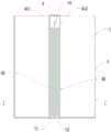
图4为本实用新型公开的液冷管与壳体装配结构平面图;Fig. 4 is a plan view of the assembly structure of the liquid cooling tube and the shell disclosed by the utility model;
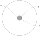
图5为本实用新型公开的液冷管A-A处平面剖视图;Fig. 5 is a plane sectional view of the liquid cooling tube A-A disclosed by the utility model;
图6为本实用新型公开的液冷管A-A处平面剖视图;Fig. 6 is a plane sectional view of the liquid cooling tube A-A disclosed by the utility model;
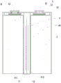
图7为本实用新型公开的集成液冷结构的圆柱电池的平面剖视图;Fig. 7 is a plane sectional view of a cylindrical battery with an integrated liquid cooling structure disclosed by the utility model;
图8为图7中B处局部放大图;Fig. 8 is a partial enlarged view of place B in Fig. 7;
图9为本实用新型公开的盖板组件的立体结构示意图;Fig. 9 is a schematic diagram of the three-dimensional structure of the cover plate assembly disclosed by the utility model;
附图标识:Drawing logo:
1、壳体;2、卷芯;3、盖板组件;10、容置腔室;4、液冷管;11、进液口;12、出液口;20、卷芯孔;41、隔板;411、进液腔室;412、出液腔室;42、散热翅片;43、散热管;44、绝缘膜;31、顶盖;32、电极组件;310、安装孔;33、下绝缘件;321、极柱;322、上绝缘件;323、压块;324、集流体;325、密封件;3251、第一密封部;3252、第二密封部;311、连接孔;331、环形槽;313、注液孔;314、防爆阀。1. Housing; 2. Rolling core; 3. Cover assembly; 10. Accommodating chamber; 4. Liquid cooling tube; 11. Liquid inlet; 12. Liquid outlet; 20. Rolling core hole; 41. Partition Plate; 411, liquid inlet chamber; 412, liquid outlet chamber; 42, heat dissipation fin; 43, heat dissipation pipe; 44, insulating film; 31, top cover; 32, electrode assembly; 310, installation hole; 33, lower Insulator; 321, pole; 322, upper insulator; 323, pressing block; 324, current collector; 325, seal; 3251, first sealing part; 3252, second sealing part; 311, connection hole; 331, Annular groove; 313, liquid injection hole; 314, explosion-proof valve.
具体实施方式Detailed ways
下面将结合本实用新型实施方式,对本实用新型实施方式中的技术方案进行清楚、完整地描述,显然,所描述的实施方式仅仅是本实用新型一部分实施方式,而不是全部的实施方式。基于本实用新型中的实施方式,本领域普通技术人员在没有做出创造性劳动前提下所获得的所有其他实施方式,都属于本实用新型保护的范围。The technical solutions in the embodiments of the present invention will be clearly and completely described below in conjunction with the embodiments of the present invention. Obviously, the described embodiments are only part of the embodiments of the present invention, not all of them. Based on the embodiments of the present utility model, all other embodiments obtained by persons of ordinary skill in the art without making creative efforts belong to the scope of protection of the present utility model.
现有技术中,圆柱电池通常pack成电池模组用在新能源汽车或其他用电领域,为了实现对圆柱电池进行散热,大多是利用蛇形液冷管缠绕在电池模组中进行导热,此种散热方式虽然可以提高圆柱电池的散热效果,但蛇形液冷管与多个圆柱电池装配成组复杂,特别是针对大直径圆柱电池的散热,电池模组中除了配置多条蛇形液冷管,还会配置平铺式液冷板,这些液冷管之间和/或液冷板之间也需要通过相应连接部件来实现相互连接,一方面导致电池模组装配结构复杂,另一方面,因多个液冷部件和其他连接部件的加入,导致电池模组整体体积增加,能量密度降低。In the prior art, cylindrical batteries are usually packed into battery modules and used in new energy vehicles or other fields of electricity consumption. In order to realize heat dissipation for cylindrical batteries, serpentine liquid-cooled tubes are mostly used to conduct heat conduction in battery modules. Although this heat dissipation method can improve the heat dissipation effect of cylindrical batteries, the assembly of serpentine liquid cooling tubes and multiple cylindrical batteries is complicated, especially for the heat dissipation of large-diameter cylindrical batteries. In addition to configuring multiple serpentine liquid cooling tubes in the battery module tubes, and will also be equipped with flat liquid-cooled plates. These liquid-cooled tubes and/or liquid-cooled plates also need to be connected to each other through corresponding connecting parts. On the one hand, the assembly structure of the battery module is complicated. , due to the addition of multiple liquid cooling components and other connecting components, the overall volume of the battery module increases and the energy density decreases.
现有技术中的圆柱电池和液冷部件均是相互独立的,仅在组成电池模组时进行连接,相互之间关联集成度较低,同时这些液冷结构和圆柱电池组成的电池模组存在结构复杂、能量密度偏低。Cylindrical batteries and liquid-cooled components in the prior art are independent of each other and are only connected when forming a battery module, and the degree of integration between them is relatively low. Complex structure and low energy density.
为此,为了解决上述问题,本实用新型实施例提出的方案是:提供了一种集成液冷结构的圆柱电池及电池模组,参照图1所示,结合图2和3,本实施例的圆柱电池包括壳体1、卷芯2及盖板组件3,壳体1内具有一端开口的容置腔室10,卷芯2设置在容置腔室10内,盖板组件3密封设置在壳体1的开口端并与卷芯2相连接。For this reason, in order to solve the above problems, the solution proposed by the embodiment of the present invention is to provide a cylindrical battery and battery module with an integrated liquid cooling structure, as shown in Figure 1, combined with Figures 2 and 3, the embodiment of the present invention The cylindrical battery includes a
为了使液冷部件集成在圆柱电池上,本实施例的圆柱电池还包括液冷管4,液冷管4一端开口,另一端封闭,液冷管4设置在容置腔室10内并与壳体1同轴,液冷管4具有开口的一端与容置腔室10内底面固定连接,卷芯2的中心轴线处设置有卷芯孔20,液冷管4封闭的一端穿过卷芯孔20并与盖板组件3固定连接,壳体1外底面设置有与液冷管4内腔相连通的进液口11和出液口12。In order to integrate the liquid cooling components on the cylindrical battery, the cylindrical battery of this embodiment also includes a
采用上述结构设置,通过在壳体1中心轴线处固定设置液冷管4,将卷芯2插入到壳体1内,使液冷管4穿过卷芯2上的卷芯孔20来与盖板组件3固定连接,通过在壳体1外底面设置与液冷内腔连通的进液口11和出液冷口,可以实现向液冷管4内部循环通入冷却介质,从而实现对壳体1内部的卷芯2进行散热。通过在壳体1内部集成液冷管4,并使卷芯2套设在液冷管4来构成圆柱电池,在圆柱电池组成电池模组过程中,圆柱电池可以通过自身集成的液冷结构来实现散热,无需在单体电池外壳上安装其他散热结构,圆柱电池更加轻量化,避免通过传统散热结构和圆柱电池装配带来的复杂程度,同时大大提高圆柱电池模组的能量密度。With the above structure, by fixing the
另外,现有技术中在圆柱电池底面铺设水平液冷板及在圆柱电池外表面缠绕蛇形液冷板的结构,均只是对圆柱电池外表面进行散热,但圆柱电池中卷芯2的能量密度较高,圆柱电池在充放电过程中,其中部的温度是最高的,圆柱电池中部的热量慢慢向外周传递,而现有技术中通过对圆柱电池表面进行散热,无法第一时间对圆柱电池中部进行散热,在高功率或大圆柱电池使用过程中,圆柱电池中心温度过高时,极易引发热失控,导致圆柱电池爆炸。In addition, in the prior art, the structure of laying a horizontal liquid cold plate on the bottom surface of the cylindrical battery and winding the serpentine liquid cold plate on the outer surface of the cylindrical battery only dissipates heat from the outer surface of the cylindrical battery, but the energy density of the winding
而本实用新型实施例通过在壳体1中部设置液冷管4,通过对卷芯2中部进行散热,可以大大降低圆柱电池充放电时中心温度,避免圆柱电池中心温度过高而发生热失控。However, in the embodiment of the present invention, by setting the
为了能够实现冷却液在液冷管4中循环,本实施例在液冷管4内中心轴线处设置有隔板41,隔板41的一端与容置腔室10内底面固定连接,隔板41的另一端朝液冷管4的封闭端延伸,隔板41将液冷管4内腔分割为相互连通的进液腔室411和出液腔室412,进液口11与进液腔室411相连通,出液口12与出液腔室412相连通。由此设置,冷却液通过进液口11进入到进液腔室411,沿圆柱电池轴向方向向上流动,然后经过隔板41顶面与液冷管4之间的通道流入到出液腔室412内,最后经出液口12排出,冷却液在进液腔室411和出液腔室412中一上一下流动,一方面可以实现冷却液在液冷管4内腔中循环,另一方面,可以实现液冷管4内部的冷却液始终处于均温状态,从而实现卷芯2中部换热均匀。In order to realize the circulation of the cooling liquid in the liquid-cooled
参照附图4-6所示,为了提高卷芯2中部散热效率,进液腔室411和出液腔室412沿液冷管4轴向方向上均设置有多个散热翅片42,多个散热翅片42沿液冷管4径向方向等间距排布,散热翅片远离进液口的一端与液冷管内顶面之间设置有间隙。由此可以保证,进液腔室和出液腔室内的冷却液可以流通,不会被散热翅片进行阻挡。Referring to Figures 4-6, in order to improve the heat dissipation efficiency in the middle of the winding
进液腔室411和出液腔室412沿液冷管4轴向方向上设置有多个散热管43,多个所述散热管43沿液冷管4径向呈蜂窝状排布,散热管远离进液口的一端与液冷管内顶面之间设置有间隙。由此可以保证,进液腔室和出液腔室内的冷却液可以流通,不会被散热管进行阻挡。The
值得注意的是,散热翅片宽度方向两侧与液冷管内腔侧壁相连接,散热管相互之间呈蜂窝状排布,相邻两个散热管侧壁相互连接,最外侧的散热管与液冷管内腔侧壁相连接。It is worth noting that the two sides in the width direction of the cooling fins are connected to the side walls of the liquid cooling tubes, the cooling tubes are arranged in a honeycomb shape, the side walls of two adjacent cooling tubes are connected to each other, and the outermost cooling tube is connected to the The side walls of the inner cavity of the liquid cooling tube are connected.
采用上述技术方案,一方面,可以通过散热翅片42或散热管43增大冷却液的换热面积,另一方面,多个散热翅片42或散热管43沿液冷管4径向方向等间距布置,可以散热翅片42或散热管43之间的冷却液流量均匀,进而使卷芯2中部散热均匀。By adopting the above-mentioned technical scheme, on the one hand, the heat exchange area of the cooling liquid can be increased through the
在本实施例中,液冷管4的材质为金属材质,优选为和壳体1一样的材质,为了避免壳体1和卷芯2之间发生短路,液冷管4外周壁上包裹有绝缘膜44,从而实现液冷管4和卷芯2之间电性隔离。In this embodiment, the
作为一些较佳实施方式,参照附图7-9,盖板组件3包括顶盖31及两个电极组件32,顶盖31中心处设置有供液冷管4穿过的安装孔310,液冷管4穿过安装孔310后,和顶盖31外表面齐平,通过液冷管4和顶盖31连接处进行焊接,可以实现液冷管4在壳体1内与顶盖31之间保持固定。两个所述电极组件32相对于所述安装孔310对称固定设置在顶盖31上,两个所述电极组件32分别与卷芯2上的正极极耳和负极极耳相连接。通过在顶盖31上设置两个电极组件32,使的正负极在圆柱电池的同一端,使得电池的空间利用率提高,更一步让电池能量密度提高。As some preferred implementation modes, referring to the accompanying drawings 7-9, the
在本实施例中,盖板组件3还包括位于顶盖31底面的下绝缘件33,所述电极组件32包括极柱321、上绝缘件322、压块323及集流体324,所述压块323、上绝缘件322、顶盖31及下绝缘件33顺次层叠设置,所述极柱321顺次穿过所述下绝缘件33、顶盖31、上绝缘件322及压块323进行铆接,所述集流体324一端与极柱321相连接,另一端与卷芯2上的极耳相连接。由此设置,极柱321穿过下绝缘件33、顶盖31、上绝缘件322后通过和压块323进行铆接,来实现将极柱321和顶盖31进行铆接固定,下绝缘件33设置在集流体324和顶盖31之间,可以避免集流体324与顶盖31接触短路。在本实施例中,极柱321铆接工艺属于现有技术。In this embodiment, the
在本实施例中,电极组件32还包括密封件325,所述密封件325包括相互连接的第一密封部3251和第二密封部3252,所述顶盖31上开设有供所述极柱321穿过的连接孔311,所述第一密封部3251设置于所述连接孔311中,并抵紧于所述连接孔311的内壁与极柱321之间,所述下绝缘件33上设置有围绕所述连接孔311的环形槽331,所述第二密封部3252容纳于所述环形槽331中。通过第一密封部3251的设置,可以将极柱321与连接孔311之间进行密封,避免电解液从极柱321与连接孔311之间的间隙中泄露通过第二密封部3252嵌入到环形槽331中,第二密封部3252的上部抵持顶盖31,下部抵持极柱321,可以实现下绝缘件33和顶盖31之间的密封,避免电解液通过下绝缘件33和顶盖31之间的间隙泄露。In this embodiment, the
在本实施例中,顶盖31上还开设有注液孔313及防爆阀314,通过注液孔313可以实现向壳体1内添加电解液,通过防爆阀314可以在电池内部压力过大时,起到泄压作用。In this embodiment, the
本实用新型还公开了一种电池模组,包括多个所述的圆柱电池,多个所述圆柱电池并排设置。在圆柱电池组成电池模组过程中,圆柱电池可以通过自身集成的液冷结构来实现散热,无需在圆柱电池外壳上安装其他散热结构,圆柱电池更加轻量化,避免通过传统散热结构和圆柱电池装配带来的复杂程度,同时大大提高圆柱电池模组的能量密度。The utility model also discloses a battery module, which comprises a plurality of the cylindrical batteries, and the plurality of cylindrical batteries are arranged side by side. In the process of forming a battery module from a cylindrical battery, the cylindrical battery can dissipate heat through its own integrated liquid cooling structure, without installing other heat dissipation structures on the cylindrical battery casing, and the cylindrical battery is lighter in weight, avoiding the traditional heat dissipation structure and cylindrical battery assembly The degree of complexity brought by it greatly improves the energy density of the cylindrical battery module.
以上仅为本实用新型的较佳实施方式而已,并不用以限制本实用新型,凡在本实用新型的精神和原则之内,所作的任何修改、等同替换、改进等,均应包含在本实用新型的保护范围之内。The above is only a preferred embodiment of the utility model, and is not intended to limit the utility model. Any modifications, equivalent replacements, improvements, etc. made within the spirit and principles of the utility model should be included in the utility model. within the scope of the new protection.
Claims (10)
Priority Applications (1)
| Application Number | Priority Date | Filing Date | Title |
|---|---|---|---|
| CN202222961007.2U CN218731279U (en) | 2022-11-08 | 2022-11-08 | Cylindrical battery and battery module of integrated liquid cooling structure |
Applications Claiming Priority (1)
| Application Number | Priority Date | Filing Date | Title |
|---|---|---|---|
| CN202222961007.2U CN218731279U (en) | 2022-11-08 | 2022-11-08 | Cylindrical battery and battery module of integrated liquid cooling structure |
Publications (1)
| Publication Number | Publication Date |
|---|---|
| CN218731279U true CN218731279U (en) | 2023-03-24 |
Family
ID=85610375
Family Applications (1)
| Application Number | Title | Priority Date | Filing Date |
|---|---|---|---|
| CN202222961007.2U Active CN218731279U (en) | 2022-11-08 | 2022-11-08 | Cylindrical battery and battery module of integrated liquid cooling structure |
Country Status (1)
| Country | Link |
|---|---|
| CN (1) | CN218731279U (en) |
Cited By (4)
| Publication number | Priority date | Publication date | Assignee | Title |
|---|---|---|---|---|
| CN116315016A (en) * | 2023-03-28 | 2023-06-23 | 楚能新能源股份有限公司 | A square battery, battery module and battery pack |
| CN118431609A (en) * | 2023-09-08 | 2024-08-02 | 重庆太蓝新能源有限公司 | Battery module, module containing ring-shaped battery and power-consuming device |
| WO2025066966A1 (en) * | 2023-09-26 | 2025-04-03 | 双澳储能科技(西安)有限公司 | Large-capacity battery, energy storage device, glue injection sealing method for large-capacity battery, glue injection mold, and terminal post adapter |
| WO2025261219A1 (en) * | 2024-06-20 | 2025-12-26 | 武汉路特斯汽车有限公司 | Battery, battery pack, and electric device |
-
2022
- 2022-11-08 CN CN202222961007.2U patent/CN218731279U/en active Active
Cited By (6)
| Publication number | Priority date | Publication date | Assignee | Title |
|---|---|---|---|---|
| CN116315016A (en) * | 2023-03-28 | 2023-06-23 | 楚能新能源股份有限公司 | A square battery, battery module and battery pack |
| CN116315016B (en) * | 2023-03-28 | 2025-08-29 | 楚能新能源股份有限公司 | A square battery, battery module and battery pack |
| CN118431609A (en) * | 2023-09-08 | 2024-08-02 | 重庆太蓝新能源有限公司 | Battery module, module containing ring-shaped battery and power-consuming device |
| CN118431609B (en) * | 2023-09-08 | 2025-07-11 | 重庆太蓝新能源有限公司 | Battery module, module comprising annular battery and electric equipment |
| WO2025066966A1 (en) * | 2023-09-26 | 2025-04-03 | 双澳储能科技(西安)有限公司 | Large-capacity battery, energy storage device, glue injection sealing method for large-capacity battery, glue injection mold, and terminal post adapter |
| WO2025261219A1 (en) * | 2024-06-20 | 2025-12-26 | 武汉路特斯汽车有限公司 | Battery, battery pack, and electric device |
Similar Documents
| Publication | Publication Date | Title |
|---|---|---|
| CN114628866A (en) | A high energy density cylindrical battery and its assembly process | |
| CN211480235U (en) | battery pack | |
| CN219144456U (en) | Battery pack | |
| CN219658914U (en) | Single battery and battery pack | |
| CN217589199U (en) | Battery cell carrier and power battery | |
| CN116526015A (en) | Battery module and energy storage system | |
| WO2024251069A1 (en) | High-capacity battery and outer housing | |
| CN116387685B (en) | Heat dissipation cylinder lithium cell and battery heat dissipation module with from inhaling function | |
| CN218123544U (en) | A battery case with integrated liquid cooling structure | |
| CN219226380U (en) | A new energy power battery pack with heat dissipation structure | |
| CN221239666U (en) | Battery module, module comprising annular battery and electric equipment | |
| WO2025261219A1 (en) | Battery, battery pack, and electric device | |
| CN221201301U (en) | Battery with cooling channel | |
| CN219350374U (en) | Single battery and electric vehicle | |
| CN220797038U (en) | High-capacity battery and shell | |
| CN111540978A (en) | A lithium-ion battery photo frame filled with phase change material | |
| CN219144347U (en) | A large-capacity battery casing and a large-capacity battery | |
| CN216671797U (en) | Power battery module of integrated liquid cooling board subassembly | |
| CN222690794U (en) | Cylindrical battery pack | |
| CN218887361U (en) | Battery, battery pack and vehicle with battery pack | |
| CN223363216U (en) | Heat exchange component, upper cover assembly, single battery and battery module | |
| CN221766847U (en) | Cooling structure and battery pack | |
| CN222190879U (en) | Cylindrical battery and electric equipment | |
| CN118431609B (en) | Battery module, module comprising annular battery and electric equipment | |
| CN221102207U (en) | A straight tube fluid circulation cooling system for power batteries |
Legal Events
| Date | Code | Title | Description |
|---|---|---|---|
| GR01 | Patent grant | ||
| GR01 | Patent grant |