CN218728221U - Fiber grating with pre-twist structure - Google Patents
Fiber grating with pre-twist structure Download PDFInfo
- Publication number
- CN218728221U CN218728221U CN202222864456.5U CN202222864456U CN218728221U CN 218728221 U CN218728221 U CN 218728221U CN 202222864456 U CN202222864456 U CN 202222864456U CN 218728221 U CN218728221 U CN 218728221U
- Authority
- CN
- China
- Prior art keywords
- fixedly connected
- equipment
- rubber
- sleeve
- fiber grating
- Prior art date
- Legal status (The legal status is an assumption and is not a legal conclusion. Google has not performed a legal analysis and makes no representation as to the accuracy of the status listed.)
- Active
Links
Images



Landscapes
- Gasket Seals (AREA)
Abstract
The utility model belongs to the technical field of fiber bragg gratings, in particular to a fiber bragg grating with a pre-twist structure, which comprises a rubber sleeve and a connecting mechanism arranged inside the rubber sleeve, wherein the connecting mechanism comprises a rotating component and a clamping component; the runner assembly includes protective housing, nut hole axle, coupling sleeve, screw hole axle, screw thread recess hole and bearing, one side fixedly connected with protective housing of rubber sleeve, the utility model discloses a set up connecting groove, when equipment is installed, the rubber sleeve of installation carries out certain protection work for the fibre core in the outside for fixed connection with the protective housing, then the protective housing can carry out the block through connecting the joint block between bolt and chute piece and the connecting groove and be connected, carry out certain connection between with equipment fixedly, and be convenient for the dismantlement work between the equipment, and when the position of the joint block of installation between and chute piece was fixed state, the assurance equipment carries out the fixed of position when installing, prevent to take place the skew and cause the harm.
Description
Technical Field
The utility model relates to a fiber grating technical field specifically is a fiber grating of pre-twist structure.
Background
The fiber grating has the characteristics of small volume, low loss, high coupling, good wavelength selectivity and the like, so the fiber grating has wide application in the field of fiber sensing. The existing fiber grating is generally written by directly scanning a common single-mode fiber with a carbon dioxide laser in a radial direction.
However, in the conventional fiber grating, since the elements inside the device are not accurately positioned when in use, and the elements inside the device are damaged when bent to a certain degree when in use, a fiber grating having a pre-twisted structure has been proposed to solve the above-mentioned problems.
SUMMERY OF THE UTILITY MODEL
In order to compensate prior art's not enough, solve fiber grating and lead to causing certain harm when using between the inside component of equipment owing to can't carry out accurate location when using, and can lead to the fact the problem of harm to equipment inside when carrying out certain bending when using, the utility model provides a fiber grating of structure of buckling in advance.
The utility model provides a technical scheme that its technical problem adopted is: the fiber bragg grating with the pre-twisted structure comprises a rubber sleeve and a connecting mechanism arranged in the rubber sleeve, wherein the connecting mechanism comprises a rotating component and a clamping component;
the rotating assembly comprises a protective shell, a nut hole shaft, a connecting shaft sleeve, a threaded hole shaft, a threaded groove hole and a bearing, wherein the protective shell is fixedly connected to one side of the rubber sleeve, the connecting shaft sleeve is fixedly connected to one side of the protective shell, the threaded groove hole is formed in the connecting shaft sleeve, the threaded hole shaft is rotatably connected to the interior of the threaded groove hole, the bearing is fixedly connected to the interior of the connecting shaft sleeve, and the nut hole shaft is fixedly connected to the interior of the threaded hole shaft;
the clamping assembly comprises a connecting groove, a connecting clamping bolt and a chute block, the connecting groove is formed in the connecting shaft sleeve, the connecting clamping bolt is fixedly connected to the inside of the protective shell, and the chute block is fixedly connected to the inner wall of the connecting clamping bolt.
Preferably, the inner wall laminating of rubber sleeve is connected with the rubber axle, the inside fixedly connected with go-between of rubber axle, the inside fixedly connected with seal of go-between, the inside fixedly connected with fibre core of seal, the inner wall fixedly connected with spacing ring of protective housing.
Preferably, the rubber sleeve is fixedly connected with the protective shell, and the protective shell is connected with the connecting groove in a clamping manner through the connecting clamping bolt and the chute block.
Preferably, the threaded hole shaft is connected with the bearing in a clamping mode, and the connecting shaft sleeve is rotatably connected with the threaded hole shaft through the threaded groove hole.
Preferably, the chute block is provided with three groups along the inner wall of the connecting clamping bolt, and the inner wall of the connecting groove is of a gear-shaped structure.
Preferably, the sealing body has a rubber-like structure, and the core is fixedly connected along the inside of the sealing body.
Preferably, the outer side of the sealing body is uniformly distributed with connecting rings, and the connecting rings are fixedly connected through rubber shafts.
The utility model discloses an useful part lies in:
1. the utility model discloses a set up the connecting groove, when equipment is installed, the rubber sleeve of installation carries out certain protection work to the fibre core in the outside for fixed connection with the protective housing, then the protective housing can carry out block connection through connecting the joint block between hitch and chute piece and the connecting groove, carry out certain connection between the equipment and fix, and the dismantlement work between the equipment of being convenient for, and when the position of the joint block of installation between and chute piece is the fixed state, guarantee that equipment carries out the fixed of position when installing, prevent to take place the skew and cause the harm;
2. the utility model discloses a set up the rubber axle, the outside evenly distributed of equipment internally mounted's seal has the go-between, will carry out certain fixed fixing between the seal of installation and carry out the fixing between the equipment, then the go-between carries out fixed connection between through the rubber axle, can carry out certain distortion, and the recovery between the equipment of being convenient for, improve equipment's work efficiency prevents that the excessive distortion of equipment from causing certain harm to equipment.
Drawings
In order to more clearly illustrate the embodiments of the present invention or the technical solutions in the prior art, the drawings needed to be used in the description of the embodiments or the prior art will be briefly described below, it is obvious that the drawings in the following description are only some embodiments of the present invention, and for those skilled in the art, other drawings can be obtained according to the drawings without inventive exercise.
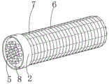
FIG. 1 is a schematic view of the overall structure of the present invention;
FIG. 2 is a schematic view of the internal structure of the rubber sleeve of the present invention;
FIG. 3 is a schematic view of the structure of the threaded hole shaft of the present invention;
fig. 4 is a schematic view of the protective shell structure of the present invention.
In the figure: 1. a rubber sleeve; 2. a protective shell; 3. a nut bore axis; 4. a connecting shaft sleeve; 5. a fiber core; 6. a rubber shaft; 7. a connecting ring; 8. a seal body; 9. a threaded bore shaft; 10. a threaded recess bore; 11. a bearing; 12. a connecting groove; 13. connecting the clamping bolt; 14. a chute block; 15. a limit ring.
Detailed Description
The technical solutions in the embodiments of the present invention will be described clearly and completely with reference to the accompanying drawings in the embodiments of the present invention, and it is obvious that the described embodiments are only some embodiments of the present invention, not all embodiments. Based on the embodiments in the present invention, all other embodiments obtained by a person skilled in the art without creative efforts belong to the protection scope of the present invention.
Example one
Referring to fig. 1-4, a fiber grating with a pre-twisted structure includes a rubber sleeve 1 and a connection mechanism disposed inside the rubber sleeve 1, where the connection mechanism includes a rotation component and a clamping component;
the rotating assembly comprises a protective shell 2, a nut hole shaft 3, a connecting shaft sleeve 4, a threaded hole shaft 9, a threaded groove hole 10 and a bearing 11, wherein the protective shell 2 is fixedly connected to one side of the rubber sleeve 1, the connecting shaft sleeve 4 is fixedly connected to one side of the protective shell 2, the threaded groove hole 10 is formed in the connecting shaft sleeve 4, the threaded hole shaft 9 is rotatably connected to the inside of the threaded groove hole 10, the bearing 11 is fixedly connected to the inside of the connecting shaft sleeve 4, and the nut hole shaft 3 is fixedly connected to the inside of the threaded hole shaft 9;
the block subassembly includes connecting groove 12, connection bayonet catch 13 and chute piece 14, and the inside of connecting axle sleeve 4 is provided with connecting groove 12, and the inside fixedly connected with of protective housing 2 connects bayonet catch 13, connects the inner wall fixedly connected with chute piece 14 of bayonet catch 13.
Further, rubber sleeve 1 is fixed connection with protective housing 2, protective housing 2 is connected for the block through connecting cotter 13 and chute block 14 and coupling groove 12, when equipment is installed, certain protection work is carried out for fixed connection to the fibre core 5 in the outside to rubber sleeve 1 of installation and protective housing 2, then protective housing 2 can carry out the block through connecting cotter 13 and chute block 14 and coupling groove 12 between be connected, carry out certain connection between the equipment fixedly, and be convenient for the dismantlement work between the equipment, and between the position of connecting cotter 13 of installation and chute block 14 when the fixed state, guarantee that equipment carries out the fixed of position when installing, prevent to take place the skew and cause the harm.
Further, the threaded hole shaft 9 is connected with the bearing 11 in a clamping mode, the connecting shaft sleeve 4 is connected with the threaded hole shaft 9 in a rotating mode through the threaded groove hole 10, when the clamping connection between the devices is fixed, the installed threaded hole shaft 9 is connected with the bearing 11 in a clamping mode, then the connecting shaft sleeve 4 is connected with the threaded hole shaft 9 in a rotating mode through the threaded groove hole 10, certain fixed connection is conducted between the devices, and the devices are convenient to detach and install.
Further, chute block 14 is provided with three groups along the inner wall of connecting the bayonet catch 13, the inner wall of connecting groove 12 is gear column structure, when equipment carries out the during operation, carries out the block connection and carries out certain fixed, and the chute block 14 of installation is provided with three groups along the inner wall of connecting the bayonet catch 13, when equipment carry out with the block connection between connecting groove 12 carry out the bolt fixed, the degree of depth of the bolt between the adjustment device when the inner wall of the connecting groove 12 of installation can carry out the block with equipment between the equipment for gear column structure, is convenient for carry out the regulation of block connection between the equipment.
Example two
Please refer to fig. 1 and 4, a first comparative example, as another implementation manner of the present invention, an inner wall of the rubber sleeve 1 is attached to a rubber shaft 6, an inner fixed connection ring 7 of the rubber shaft 6 is connected to the inner wall, an inner fixed connection seal body 8 of the connection ring 7 is connected to the inner wall, an inner fixed connection fiber core 5 of the seal body 8 is connected to the inner wall of the protective shell 2 is connected to a limiting ring 15.
Further, the seal 8 is of a rubber-like structure, the fiber cores 5 are fixedly connected along the inside of the seal 8, the seal 8 installed between the devices is of a rubber-like structure, the installed fiber cores 5 are fixedly connected along the inside of the seal 8, the fiber cores 5 between the devices are separated, isolation between the devices and insulation protection are facilitated, and damage is caused between the devices.
Further, the outside evenly distributed of seal 8 has go-between 6, go-between 7 carries out fixed connection through between the rubber axle 6, and the outside evenly distributed of seal 8 of equipment internally mounted has go-between 6, carries out certain fixed fixing between the seal 8 that will install and carries out the fixed between the equipment, then go-between 7 carries out fixed connection through between the rubber axle 6, can carry out certain distortion, and the recovery between the equipment of being convenient for, improve equipment's work efficiency prevents that equipment excessive distortion from leading to the fact certain harm to equipment.
The working principle is that firstly, when equipment is installed to a certain extent, the installed rubber sleeve 1 and the installed protective shell 2 are fixedly connected to the outside fiber core 5 to perform certain protection work, then the protective shell 2 can be connected with the inclined groove block 14 and the connecting groove 12 in a clamping mode through the connecting clamping bolt 13, certain connection and fixation are performed between the equipment, and convenience is brought to disassembly work between the equipment, when the positions of the connecting clamping bolt 13 and the inclined groove block 14 which are installed between the protective shell and the protective shell are in a fixed state, the equipment is guaranteed to be fixed in position when being installed, damage caused by deviation is prevented, three groups of inclined groove blocks 14 which are installed are arranged along the inner wall of the connecting clamping bolt 13, when the equipment is connected with the connecting groove 12 in a clamping mode to perform bolt fixation, the depth of a bolt between the equipment can be adjusted when the equipment is clamped between the equipment through the gear-shaped structure, then the connecting shaft sleeve 4 is rotatably connected with the threaded hole shaft 9 through the threaded groove hole 10, certain fixed connection between the equipment is performed, and convenience is brought to disassembly and installation between the equipment.
Finally, carry out certain fixed protection to equipment, the inside fixed connection of 8 seals is followed to the fibre core 5 of installation, separate between 5 fibre cores between the equipment, and be convenient for isolation between the equipment and carry out insulation protection, then 8 seals's of equipment internally mounted outside evenly distributed has go-between 6, carry out certain fixed the carrying on between the equipment fixing between the seal 8 of installation, then go-between 7 carries out fixed connection between through rubber shaft 6, can carry out certain distortion, and be convenient for the recovery between the equipment, improve equipment's work efficiency.
In the description herein, references to the description of "one embodiment," "an example," "a specific example," etc., mean that a particular feature, structure, material, or characteristic described in connection with the embodiment or example is included in at least one embodiment or example of the invention. In this specification, the schematic representations of the terms used above do not necessarily refer to the same embodiment or example. Furthermore, the particular features, structures, materials, or characteristics described may be combined in any suitable manner in any one or more embodiments or examples.
The foregoing shows and describes the general principles, essential features, and advantages of the invention. It will be understood by those skilled in the art that the present invention is not limited to the above embodiments, and that the foregoing embodiments and descriptions are provided only to illustrate the principles of the present invention without departing from the spirit and scope of the present invention.
Claims (7)
1. The utility model provides a fiber grating of structure of prewarping, includes rubber sleeve (1) and sets up the coupling mechanism in rubber sleeve (1) inside, its characterized in that: the connecting mechanism comprises a rotating component and a clamping component;
the rotating assembly comprises a protective shell (2), a nut hole shaft (3), a connecting shaft sleeve (4), a threaded hole shaft (9), a threaded groove hole (10) and a bearing (11), wherein the protective shell (2) is fixedly connected to one side of the rubber sleeve (1), the connecting shaft sleeve (4) is fixedly connected to one side of the protective shell (2), the threaded groove hole (10) is formed in the connecting shaft sleeve (4), the threaded hole shaft (9) is rotatably connected to the inside of the threaded groove hole (10), the bearing (11) is fixedly connected to the inside of the connecting shaft sleeve (4), and the nut hole shaft (3) is fixedly connected to the inside of the threaded hole shaft (9);
the clamping assembly comprises a connecting groove (12), a connecting clamp bolt (13) and a chute block (14), the connecting groove (12) is arranged inside the connecting shaft sleeve (4), the connecting clamp bolt (13) is fixedly connected inside the protective shell (2), and the chute block (14) is fixedly connected to the inner wall of the connecting clamp bolt (13).
2. The fiber grating of claim 1, wherein: the inner wall laminating of rubber sleeve (1) is connected with rubber axle (6), the inside fixedly connected with go-between (7) of rubber axle (6), the inside fixedly connected with seal (8) of go-between (7), the inside fixedly connected with fibre core (5) of seal (8), the inner wall fixedly connected with spacing ring (15) of protective housing (2).
3. The fiber grating of claim 1, wherein: rubber sleeve (1) is fixed connection with protective housing (2), protective housing (2) are connected for the block through connecting clamp bolt (13) and chute piece (14) and connecting groove (12).
4. The fiber grating of claim 1, wherein: the threaded hole shaft (9) is connected with the bearing (11) in a clamping mode, and the connecting shaft sleeve (4) is rotatably connected with the threaded hole shaft (9) through the threaded groove hole (10).
5. The fiber grating of claim 1, wherein: the inner wall that the chute piece (14) was followed connection bayonet catch (13) is provided with three groups, the inner wall of connecting groove (12) is the gear column structure.
6. The fiber grating of claim 2, wherein: the sealing body (8) is of a rubber-like structure, and the fiber cores (5) are fixedly connected along the inside of the sealing body (8).
7. The fiber grating of claim 2, wherein: the outer side of the sealing body (8) is uniformly distributed with connecting rings (7), and the connecting rings (7) are fixedly connected through rubber shafts (6).
Priority Applications (1)
| Application Number | Priority Date | Filing Date | Title |
|---|---|---|---|
| CN202222864456.5U CN218728221U (en) | 2022-10-29 | 2022-10-29 | Fiber grating with pre-twist structure |
Applications Claiming Priority (1)
| Application Number | Priority Date | Filing Date | Title |
|---|---|---|---|
| CN202222864456.5U CN218728221U (en) | 2022-10-29 | 2022-10-29 | Fiber grating with pre-twist structure |
Publications (1)
| Publication Number | Publication Date |
|---|---|
| CN218728221U true CN218728221U (en) | 2023-03-24 |
Family
ID=85594853
Family Applications (1)
| Application Number | Title | Priority Date | Filing Date |
|---|---|---|---|
| CN202222864456.5U Active CN218728221U (en) | 2022-10-29 | 2022-10-29 | Fiber grating with pre-twist structure |
Country Status (1)
| Country | Link |
|---|---|
| CN (1) | CN218728221U (en) |
-
2022
- 2022-10-29 CN CN202222864456.5U patent/CN218728221U/en active Active
Similar Documents
| Publication | Publication Date | Title |
|---|---|---|
| CN110212485A (en) | Three core high-voltage undersea cable connector boxs of one kind and its installation method | |
| CN211180307U (en) | Photoelectric combined micro slip ring | |
| WO2025082207A1 (en) | Large-water-depth optical fiber splicing box | |
| CN102073107A (en) | Underground optical cable connecting device | |
| CN105179502A (en) | Insulation coupler and replacement method thereof | |
| CN213332108U (en) | Universal shaft for ship | |
| CN212717680U (en) | Simple tooth type coupling | |
| CN213521179U (en) | Sealing element for shielding cylinder and shielding cylinder easy to install | |
| CN115163729A (en) | Circumferential array type inhaul cable vibration energy dissipation ring based on acoustic black hole beam | |
| CN219627510U (en) | Motor and gear box integrated configuration | |
| CN220815567U (en) | Mobilizable oil pipe short circuit for oil well | |
| CN214007529U (en) | Centrifugal pump | |
| CN208503294U (en) | A kind of high-accuracy shaft coupling | |
| CN207701621U (en) | A kind of mechanical seal bearing protection formula drive mechanism | |
| CN218122298U (en) | Sealing protection structure for bendable optical cable connector and optical cable connector | |
| CN220872712U (en) | High-precision integrated FC optical fiber connector | |
| CN223285407U (en) | Integrated photoelectric liquid slip ring | |
| CN220646530U (en) | Bearing housing convenient to installation | |
| CN218630301U (en) | Optical cable fixing device for buried pipeline construction | |
| CN222338599U (en) | Reinforced type horsehead | |
| CN201859231U (en) | Single-core optical fiber rotary connector | |
| CN221033122U (en) | Compressor device | |
| CN218266864U (en) | Sealed coupling | |
| CN218427656U (en) | Grinding rod flexible shaft protective sleeve fixing device for steel pipe internal grinding | |
| CN223664819U (en) | An optical transmission protection device |
Legal Events
| Date | Code | Title | Description |
|---|---|---|---|
| GR01 | Patent grant | ||
| GR01 | Patent grant |