CN218717233U - Modular wind power blade fixing structure - Google Patents
Modular wind power blade fixing structure Download PDFInfo
- Publication number
- CN218717233U CN218717233U CN202223235760.XU CN202223235760U CN218717233U CN 218717233 U CN218717233 U CN 218717233U CN 202223235760 U CN202223235760 U CN 202223235760U CN 218717233 U CN218717233 U CN 218717233U
- Authority
- CN
- China
- Prior art keywords
- shell
- leeward
- windward
- fixing structure
- side shell
- Prior art date
- Legal status (The legal status is an assumption and is not a legal conclusion. Google has not performed a legal analysis and makes no representation as to the accuracy of the status listed.)
- Active
Links
Images



Classifications
-
- Y—GENERAL TAGGING OF NEW TECHNOLOGICAL DEVELOPMENTS; GENERAL TAGGING OF CROSS-SECTIONAL TECHNOLOGIES SPANNING OVER SEVERAL SECTIONS OF THE IPC; TECHNICAL SUBJECTS COVERED BY FORMER USPC CROSS-REFERENCE ART COLLECTIONS [XRACs] AND DIGESTS
- Y02—TECHNOLOGIES OR APPLICATIONS FOR MITIGATION OR ADAPTATION AGAINST CLIMATE CHANGE
- Y02E—REDUCTION OF GREENHOUSE GAS [GHG] EMISSIONS, RELATED TO ENERGY GENERATION, TRANSMISSION OR DISTRIBUTION
- Y02E10/00—Energy generation through renewable energy sources
- Y02E10/70—Wind energy
- Y02E10/72—Wind turbines with rotation axis in wind direction
Landscapes
- Wind Motors (AREA)
Abstract
本实用新型涉及模块化风电叶片技术领域,尤其涉及一种模块化风电叶片固定结构,包括相对设置迎风面壳体和背风面壳体,以及设置在迎风面壳体和背风面壳体之间的加强组件,其中:加强组件包括横向加强筋、纵向加强筋和工字梁,迎风面壳体和背风面壳体相对拼合,拼合后的截面形成完整的叶片截面结构;横向加强筋沿叶片的宽度方向贴合在迎风面壳体和背风面壳体内壁上,纵向加强筋沿与横向加强筋垂直的方向贴合在迎风面和背风面壳体的内壁上,工字梁沿风电叶片长度方向上平行设置有多条,且工字梁的顶部和底部分别与迎风面壳体、背风面壳体的内壁连接。本实用新型通过上述方式设置,使得叶片整体的抗剪能力得以提升,整体结构强度得以加强。

The utility model relates to the technical field of modularized wind power blades, in particular to a fixed structure for modularized wind power blades, which includes a windward side shell and a leeward side shell, and a shell arranged between the windward side shell and the leeward side shell. Reinforcement components, wherein: the reinforcement components include transverse reinforcement ribs, longitudinal reinforcement ribs and I-shaped beams, the windward side shell and the leeward side shell are relatively assembled, and the cross-section after combination forms a complete blade section structure; the transverse reinforcement ribs are along the width of the blade The direction is attached to the inner wall of the windward side shell and the leeward side shell, the longitudinal rib is attached to the inner wall of the windward side and the leeward side shell in the direction perpendicular to the transverse rib, and the I-beam is attached to the inner wall of the wind turbine blade along the length direction of the wind turbine blade. A plurality of beams are arranged in parallel, and the top and bottom of the I-beams are respectively connected with the inner walls of the shell on the windward side and the shell on the leeward side. The utility model is arranged in the above manner, so that the overall shear resistance of the blade can be improved, and the overall structural strength can be strengthened.
Description
技术领域technical field
本实用新型涉及模块化风电叶片技术领域,尤其涉及一种模块化风电叶片固定结构。The utility model relates to the technical field of modularized wind power blades, in particular to a fixing structure for modularized wind power blades.
背景技术Background technique
随着风电叶片朝着大型化方向的发展,传统的叶片制造方式难度也越来越大,为了提高制造和安装的便捷性,风电叶片的发展也逐渐走向模块化的方向,然而模块化的连接,对于每个模块的连接以及模块与模块之间的连接提出了更高的要求;With the development of large-scale wind power blades, the traditional blade manufacturing method is becoming more and more difficult. In order to improve the convenience of manufacturing and installation, the development of wind power blades is gradually moving towards the direction of modularization. However, the modular connection , put forward higher requirements for the connection of each module and the connection between modules;
相关技术中,对于每个模块的连接,多采用箱型分块式连接结构,如公开号为CN113323797A的中国发明专利于2021年08月31日公开的一种模块化风电叶片,其在风电叶片的宽度方向上设置前缘件、后缘件和中间件,通过螺栓的方式将三者进行紧固连接;In related technologies, for the connection of each module, a box-shaped block-type connection structure is often used, such as a modular wind power blade disclosed on August 31, 2021 in a Chinese invention patent with the publication number CN113323797A. The front edge piece, the rear edge piece and the middle piece are arranged in the width direction of the machine, and the three are fastened and connected by bolts;
然而发明人在实施上述方案时发现,上述连接方式使得叶片整体在迎风面和背风面的抗剪力有所下降,使得风电叶片的使用寿命对于连接螺栓的依赖性较强,不利于承载迎风面和背风面的载荷。However, when implementing the above solution, the inventors found that the above connection method reduces the shear force of the overall blade on the windward side and the leeward side, making the service life of wind turbine blades more dependent on the connecting bolts, which is not conducive to bearing the windward side. and loads on the leeward side.
实用新型内容Utility model content
鉴于以上技术问题中的至少一项,本实用新型提供了一种模块化风电叶片固定结构,采用连接结构的改进以提高风电叶片的抗剪能力。In view of at least one of the above technical problems, the utility model provides a modular wind power blade fixing structure, which adopts an improved connection structure to improve the shear resistance of the wind power blade.
根据本实用新型的第一方面,提供一种模块化风电叶片固定结构,包括相对设置迎风面壳体和背风面壳体,以及设置在所述迎风面壳体和背风面壳体之间的加强组件,其中:According to the first aspect of the present utility model, there is provided a modular wind turbine blade fixing structure, which includes a windward side shell and a leeward side shell oppositely arranged, and a reinforcement arranged between the windward side shell and the leeward side shell components, where:
所述加强组件包括横向加强筋、纵向加强筋和工字梁,所述迎风面壳体和背风面壳体相对拼合,拼合后的截面形成完整的叶片截面结构;所述横向加强筋沿叶片的宽度方向贴合在所述迎风面壳体和背风面壳体内壁上,所述纵向加强筋沿与所述横向加强筋垂直的方向贴合在所述迎风面和背风面壳体的内壁上,所述工字梁沿风电叶片长度方向上平行设置有多条,且所述工字梁的顶部和底部分别与所述迎风面壳体、背风面壳体的内壁连接。The reinforcement assembly includes transverse reinforcement ribs, longitudinal reinforcement ribs and I-beams, the windward side shell and the leeward side shell are joined together, and the combined cross section forms a complete blade section structure; The width direction is attached to the inner wall of the windward side shell and the leeward side shell, and the longitudinal rib is attached to the inner wall of the windward side and the leeward side shell in a direction perpendicular to the transverse rib, A plurality of I-beams are arranged in parallel along the length direction of the wind power blade, and the top and bottom of the I-beams are respectively connected to the inner walls of the windward shell and the leeward shell.
在本实用新型的一些实施例中,所述迎风面壳体和背风面壳体在宽度方向上的前缘部分均具有朝内翻折的连接部,两所述连接部呈平行设置的板状结构,所述迎风面壳体和背风面壳体的前缘部分通过所述连接部连接。In some embodiments of the present utility model, the front edge parts of the shell on the windward side and the shell on the leeward side in the width direction both have connecting parts that are folded inward, and the two connecting parts are in the shape of plates arranged in parallel. structure, the front edge parts of the shell on the windward side and the shell on the leeward side are connected through the connecting portion.
在本实用新型的一些实施例中,两所述连接部之间具有结构胶层。In some embodiments of the present invention, there is a structural adhesive layer between the two connecting parts.
在本实用新型的一些实施例中,所述迎风面壳体和背风面壳体在宽度方向的后缘位置处还具有后缘梁,所述后缘梁沿风电叶片的长度方向延伸,并且底面与所述背风面壳体的内壁贴合连接,顶面与所述迎风面壳体的内壁贴合连接。In some embodiments of the present utility model, the shell on the windward side and the shell on the leeward side further have a trailing edge beam at the position of the trailing edge in the width direction, the trailing edge beam extends along the length direction of the wind turbine blade, and the bottom surface The top surface is fitted and connected with the inner wall of the shell on the leeward side, and the top surface is fitted and connected with the inner wall of the shell on the windward side.
在本实用新型的一些实施例中,所述后缘梁包括U型梁和将所述U型梁的开口侧封闭的封板。In some embodiments of the present utility model, the trailing edge beam includes a U-shaped beam and a closing plate closing the opening side of the U-shaped beam.
在本实用新型的一些实施例中,所述纵向加强筋为T型梁,包括底板和与底板连接的竖板,所述底板与所述迎风面壳体或背风面壳体的内壁贴合。In some embodiments of the present utility model, the longitudinal reinforcement is a T-shaped beam, including a bottom plate and a vertical plate connected to the bottom plate, and the bottom plate is attached to the inner wall of the windward side shell or the leeward side shell.
在本实用新型的一些实施例中,所述纵向加强筋沿风电叶片的宽度方向平行间隔布置有多条,且所述竖板平行设置。In some embodiments of the present utility model, a plurality of longitudinal reinforcing ribs are arranged in parallel and at intervals along the width direction of the wind turbine blade, and the vertical plates are arranged in parallel.
在本实用新型的一些实施例中,所述工字梁包括中间的腹板和设置在腹板顶部和底部的翼板,两所述翼板分别与所述迎风面壳体内壁、背风面壳体内壁贴合。In some embodiments of the present utility model, the I-beam includes a middle web and wing plates arranged at the top and bottom of the web, and the two wing plates are respectively connected to the inner wall of the windward shell and the leeward shell. Inner wall fit.
在本实用新型的一些实施例中,所述工字梁沿叶片宽度方向上间隔平行设置有多个,多个所述工字梁的所述腹板平行设置。In some embodiments of the present utility model, a plurality of I-beams are arranged in parallel at intervals along the width direction of the blade, and the webs of the plurality of I-beams are arranged in parallel.
在本实用新型的一些实施例中,所述工字梁的腹板与翼板之间还具有加强块,所述加强块与所述横向加强筋对接设置。In some embodiments of the present utility model, there is a reinforcing block between the web and the wing of the I-beam, and the reinforcing block is arranged in abutment with the transverse reinforcing rib.
本实用新型的有益效果为:本实用新型通过完整的迎风面壳体和背风面壳体的设置,提供气动外形的同时使得整个面整体受力,满足了风电叶片的稳定性要求,同时,通过加强组件中工字梁的设置实现迎风面和背风面所承受载荷的传递,通过横向筋加强筋和纵向加强筋的设置,使得壳体的强度得以提升,通过上述方式设置,与现有的通过螺栓和箱型体的连接方式相比,使得叶片整体的抗剪能力得以提升,整体结构强度得以加强。The beneficial effects of the utility model are as follows: the utility model provides an aerodynamic shape through the complete setting of the windward side shell and the leeward side shell, and at the same time makes the entire surface under force, which meets the stability requirements of the wind power blades. At the same time, through The setting of the I-beam in the reinforcement component realizes the transmission of the load on the windward side and the leeward side, and the strength of the shell can be improved through the setting of the transverse and longitudinal ribs. Compared with the connection method of the bolt and the box-shaped body, the overall shear resistance of the blade can be improved, and the overall structural strength can be strengthened.
附图说明Description of drawings
为了更清楚地说明本实用新型实施例或现有技术中的技术方案,下面将对实施例或现有技术描述中所需要使用的附图作简单地介绍,显而易见地,下面描述中的附图仅仅是本实用新型中记载的一些实施例,对于本领域普通技术人员来讲,在不付出创造性劳动的前提下,还可以根据这些附图获得其他的附图。In order to more clearly illustrate the technical solutions in the embodiments of the present invention or the prior art, the following will briefly introduce the accompanying drawings that need to be used in the description of the embodiments or the prior art. Obviously, the accompanying drawings in the following description These are only some embodiments recorded in the utility model, and those skilled in the art can also obtain other drawings according to these drawings without creative work.
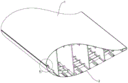
图1为本实用新型实施例中模块化风电叶片固定结构的结构示意图;Fig. 1 is a structural schematic diagram of a fixed structure of a modular wind power blade in an embodiment of the present invention;
图2为本实用新型实施例中模块化风电叶片固定结构的爆炸分解结构示意图;Fig. 2 is a schematic diagram of the exploded decomposition structure of the fixed structure of the modular wind power blade in the embodiment of the present invention;
图3为本实用新型实施例中图1中的A处局部放大图;Fig. 3 is a partial enlarged view of A place in Fig. 1 in the utility model embodiment;
图4为本实用新型实施例中模块化风电叶片固定结构的结构示意图(省略迎风面壳体);Fig. 4 is a structural schematic diagram of the fixed structure of the modular wind power blade in the embodiment of the utility model (the shell on the windward side is omitted);
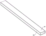
图5为本实用新型实施例中后缘梁的结构示意图;Fig. 5 is a schematic structural view of the trailing edge beam in the embodiment of the present invention;
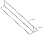
图6为本实用新型实施例中纵向加强筋的结构示意图;Fig. 6 is a structural schematic diagram of longitudinal ribs in an embodiment of the present invention;
图7为本实用新型实施例中工字梁与背风面壳体的连接结构示意图。Fig. 7 is a schematic diagram of the connection structure between the I-beam and the shell on the leeward side in the embodiment of the utility model.
具体实施方式Detailed ways
下面将结合本实用新型实施例中的附图,对本实用新型实施例中的技术方案进行清楚、完整地描述,显然,所描述的实施例仅仅是本实用新型一部分实施例,而不是全部的实施例。The technical solutions in the embodiments of the present invention will be clearly and completely described below in conjunction with the accompanying drawings in the embodiments of the present invention. Obviously, the described embodiments are only part of the embodiments of the present invention, not all of them. example.
需要说明的是,当元件被称为“固定于”另一个元件,它可以直接在另一个元件上或者也可以存在居中的元件。当一个元件被认为是“连接”另一个元件,它可以是直接连接到另一个元件或者可能同时存在居中元件。本文所使用的术语“垂直的”、“水平的”、“左”、“右”以及类似的表述只是为了说明的目的,并不表示是唯一的实施方式。It should be noted that when an element is referred to as being “fixed” to another element, it can be directly on the other element or there can also be an intervening element. When an element is referred to as being "connected to" another element, it can be directly connected to the other element or intervening elements may also be present. The terms "vertical," "horizontal," "left," "right," and similar expressions are used herein for purposes of illustration only and are not intended to represent the only embodiments.
除非另有定义,本文所使用的所有的技术和科学术语与属于本实用新型的技术领域的技术人员通常理解的含义相同。在本实用新型的说明书中所使用的术语只是为了描述具体的实施例的目的,不是旨在于限制本实用新型。本文所使用的术语“及/或”包括一个或多个相关的所列项目的任意的和所有的组合。Unless otherwise defined, all technical and scientific terms used herein have the same meaning as commonly understood by one of ordinary skill in the technical field of this invention. The terms used in the description of the utility model are only for the purpose of describing specific embodiments, and are not intended to limit the utility model. As used herein, the term "and/or" includes any and all combinations of one or more of the associated listed items.
如图1至图7所示的模块化风电叶片固定结构,包括相对设置迎风面壳体1和背风面壳体2,以及设置在迎风面壳体1和背风面壳体2之间的加强组件3,其中:The modularized wind turbine blade fixing structure shown in Figures 1 to 7 includes a windward shell 1 and a
如图2中所示,加强组件3包括横向加强筋31、纵向加强筋32和工字梁33,迎风面壳体1和背风面壳体2相对拼合,拼合后的截面形成完整的叶片截面结构;在本实用新型实施例中,迎风面壳体1和背风面壳体2均为完整的模块半壳结构,通过这种整体式的结构设计,不仅可以提高风电叶片的承载能力,更加强化了风电叶片的抗剪能力;As shown in Figure 2, the
请继续参照图2 ,在本实用新型实施例中,横向加强筋31沿叶片的宽度方向贴合在迎风面壳体1和背风面壳体2内壁上,纵向加强筋32沿与横向加强筋31垂直的方向贴合在迎风面和背风面壳体2的内壁上,工字梁33沿风电叶片长度方向上平行设置有多条,且工字梁33的顶部和底部分别与迎风面壳体1、背风面壳体2的内壁连接。通过上述横向加强筋31和纵向加强筋32的设置,使得迎风面壳体1和背风面壳体2的整体结构强度得以加强,并且通过多条工字梁33的设置,提高了迎风面壳体1和背风面壳体2之间力的传递和承载能力。Please continue to refer to Fig. 2 , in the embodiment of the present utility model, the transverse reinforcing
在上述实施例中,通过完整的迎风面壳体1和背风面壳体2的设置,提供气动外形的同时使得整个面整体受力,满足了风电叶片的稳定性要求,同时,通过加强组件3中工字梁33的设置实现迎风面和背风面所承受载荷的传递,通过横向筋加强筋和纵向加强筋32的设置,使得壳体的强度得以提升,通过上述方式设置,与现有的通过螺栓和箱型体的连接方式相比,使得叶片整体的抗剪能力得以提升,整体结构强度得以加强。In the above-mentioned embodiments, through the complete setting of the windward side shell 1 and the
在上述实施例的基础上,如图3中所示,为了进一步提高迎风面壳体1和背风面壳体2在连接时的可靠性,迎风面壳体1和背风面壳体2在宽度方向上的前缘部分均具有朝内翻折的连接部11,两连接部11呈平行设置的板状结构,迎风面壳体1和背风面壳体2的前缘部分通过连接部11连接。通过朝内翻折的连接部11的设置,提高了迎风面壳体1和背风面壳体2在连接时的接触面积,这里需要指出的是,迎风面壳体1和背风面壳体2通过连接部11进行连接的方式具有多种,可以是通过紧固件进行连接,也可以是通过结构胶进行连接。本领域技术人员可以根据需要进行选择。在本实用新型的一些实施例中,请继续参照图3,两连接部11之间具有结构胶层21。即在该实施方式中,通过结构胶的方式实现两个连接部11之间的连接,通过结构胶的连接,可以充分利用两个连接部11来增加粘接面积,进而提高粘接的可靠性。On the basis of the above-mentioned embodiment, as shown in Figure 3, in order to further improve the reliability of the connection between the windward side shell 1 and the
在上述实施例的基础上,为了提高迎风面壳体1和背风面壳体2在后缘处的连接可靠性,如图4中所示,迎风面壳体1和背风面壳体2在宽度方向的后缘位置处还具有后缘梁4,后缘梁4沿风电叶片的长度方向延伸,并且底面与背风面壳体2的内壁贴合连接,顶面与迎风面壳体1的内壁贴合连接。这样,通过后缘梁4的设置,提供了摆振方向上的刚度以及承担摆振方向的主要载荷。On the basis of the above-mentioned embodiments, in order to improve the connection reliability between the windward shell 1 and the
具体如图5中所示,在本实用新型的一些实施例中,后缘梁4包括U型梁41和将U型梁41的开口侧封闭的封板42。由于后缘梁4的顶部和底部的面要和迎风面壳体1以及背风面壳体2的内壁贴合,故在加工时存在一定难度,而通过U型梁41和封板42的组合方式,一方面可以提高后缘梁4加工的便捷性,同时通过封板42的设置,可以提高后缘梁4的整体结构强度。Specifically as shown in FIG. 5 , in some embodiments of the present invention, the trailing edge beam 4 includes a
在本实用新型实施例中,如图2和图6中所示,纵向加强筋32为T型梁,包括底板32a和与底板32a连接的竖板32b,底板32a与迎风面壳体1或背风面壳体2的内壁贴合。请参照图2,在本实用新型实施例中,由于迎风面壳体1和背风面壳体2为弧形面,故将纵向加强筋32设置为T型梁的方式,一方面可以实现T型梁的底板32a与迎风面壳体1或者背风面壳体2的内壁贴合,提高连接可靠性,另一方面通过竖板32b的设置,使得纵向加强筋32的整体结构强度得以加强。In the embodiment of the present utility model, as shown in Fig. 2 and Fig. 6, the
请继续参照图2,在本实用新型实施例中,纵向加强筋32沿风电叶片的宽度方向平行间隔布置有多条,且竖板32b平行设置。通过这种方式的设置,使得竖板32b均沿着与叶片转动方向所在平面垂直的方向设置,进而提高了叶片整体的抗剪能力。Please continue to refer to FIG. 2 , in the embodiment of the present invention, a plurality of longitudinal reinforcing
在本实用新型实施例中,关于工字梁33的具体结构形式如图7中所示,工字梁33包括中间的腹板33a和设置在腹板33a顶部和底部的翼板33b,两翼板33b分别与迎风面壳体1内壁、背风面壳体2内壁贴合。这样,通过工字梁33来传递迎风面壳体1或者背风面壳体2所承受的载荷,可以有效地将力分散,进而避免局部应力集中,提高叶片整体的可靠性。In the embodiment of the present utility model, the specific structural form of the I-
在本实用新型一些实施例中,工字梁33沿叶片宽度方向上间隔平行设置有多个,多个工字梁33的腹板33a平行设置。此外,这里还需要指出的是,在本实用新型实施例中,工字梁33与纵向加强筋32间隔设置,通过这种方式的设置,使得工字梁33也同时起到了纵向加强筋32的作用。In some embodiments of the present invention, a plurality of I-
在本实用新型实施例中,为了提高加强组件3的整体结构强度,如图2和图7中所示,工字梁33的腹板33a与翼板33b之间还具有加强块33c,加强块33c与横向加强筋31对接设置。通过这种设置,使得横向加强筋31与工字梁33产生了连接,进而能够将迎风面壳体1或者背风面壳体2所承受的载荷经过横向加强筋31和纵向加强筋32传递至工字梁33上,提高叶片整体的刚度。In the embodiment of the present invention, in order to improve the overall structural strength of the
本行业的技术人员应该了解,本实用新型不受上述实施例的限制,上述实施例和说明书中描述的只是说明本实用新型的原理,在不脱离本实用新型精神和范围的前提下,本实用新型还会有各种变化和改进,这些变化和改进都落入要求保护的本实用新型范围内。本实用新型要求保护范围由所附的权利要求书及其等效物界定。Those skilled in the art should understand that the utility model is not limited by the above-mentioned embodiments. The above-mentioned embodiments and descriptions only illustrate the principle of the utility model. Without departing from the spirit and scope of the utility model, the utility model The new model also has various changes and improvements, and these changes and improvements all fall within the scope of the claimed utility model. The scope of protection required by the utility model is defined by the appended claims and their equivalents.
Claims (10)
Priority Applications (1)
| Application Number | Priority Date | Filing Date | Title |
|---|---|---|---|
| CN202223235760.XU CN218717233U (en) | 2022-12-02 | 2022-12-02 | Modular wind power blade fixing structure |
Applications Claiming Priority (1)
| Application Number | Priority Date | Filing Date | Title |
|---|---|---|---|
| CN202223235760.XU CN218717233U (en) | 2022-12-02 | 2022-12-02 | Modular wind power blade fixing structure |
Publications (1)
| Publication Number | Publication Date |
|---|---|
| CN218717233U true CN218717233U (en) | 2023-03-24 |
Family
ID=85624978
Family Applications (1)
| Application Number | Title | Priority Date | Filing Date |
|---|---|---|---|
| CN202223235760.XU Active CN218717233U (en) | 2022-12-02 | 2022-12-02 | Modular wind power blade fixing structure |
Country Status (1)
| Country | Link |
|---|---|
| CN (1) | CN218717233U (en) |
-
2022
- 2022-12-02 CN CN202223235760.XU patent/CN218717233U/en active Active
Similar Documents
| Publication | Publication Date | Title |
|---|---|---|
| CN111560839B (en) | A large cantilever steel box girder | |
| CN115977866B (en) | Modularized wind power blade and connecting structure thereof | |
| CN113958447B (en) | Modular wind power blade chord direction blocking connection structure | |
| CN101589227A (en) | The reinforced blade that is used for wind turbine | |
| CN115355133B (en) | Modularized wide Liang Fengdian blade structure | |
| CN216767624U (en) | Large-scale modularization wind-powered electricity generation blade connection structure | |
| CN115977867B (en) | A segmented blade module structure and its forming method | |
| CN115506947B (en) | Multi-beam tension type wind power blade and manufacturing method thereof | |
| CN102733492A (en) | H-shaped steel beam and H-shaped steel column minor axis variable beam height fabricated node and construction method thereof | |
| CN113775471B (en) | Truss type modularized wind power blade | |
| CN115837974A (en) | Composite material light truss type wing rib and assembling method | |
| CN115596604B (en) | A multi-web structure modular wind power blade | |
| CN219381693U (en) | Double-web blade module bonding structure | |
| CN111396243B (en) | A large-scale wind turbine blade with three-web structure and its assembly method | |
| CN109208784A (en) | Shear wall | |
| CN210971269U (en) | A longitudinal beam structure and an automobile | |
| CN218669659U (en) | Modular wind power blade composite structure | |
| CN115539292B (en) | Wind power blade main bearing structure and assembling method thereof | |
| CN204153451U (en) | The composite material frame beam of a kind of space three-dimensional posting connects hinge support connector | |
| CN201952137U (en) | Combined transition arm support | |
| CN217834802U (en) | Modular composite material reinforcing rib structure and rib plate | |
| CN115898754B (en) | Blade module and forming method thereof | |
| CN216767623U (en) | Modular wind power blade connecting structure | |
| CN117864383A (en) | Aircraft control surface structure | |
| CN214302358U (en) | A node connection device applied to concealed columns and beams of modular steel structure shear walls |
Legal Events
| Date | Code | Title | Description |
|---|---|---|---|
| GR01 | Patent grant | ||
| GR01 | Patent grant |