CN218716191U - Sliding window - Google Patents
Sliding window Download PDFInfo
- Publication number
- CN218716191U CN218716191U CN202221982029.0U CN202221982029U CN218716191U CN 218716191 U CN218716191 U CN 218716191U CN 202221982029 U CN202221982029 U CN 202221982029U CN 218716191 U CN218716191 U CN 218716191U
- Authority
- CN
- China
- Prior art keywords
- window
- frame
- fixedly connected
- push
- sliding
- Prior art date
- Legal status (The legal status is an assumption and is not a legal conclusion. Google has not performed a legal analysis and makes no representation as to the accuracy of the status listed.)
- Active
Links
Images


Landscapes
- Wing Frames And Configurations (AREA)
Abstract
The utility model discloses an austral window, sliding sash, including the window frame, two sets of slide rails have transversely been seted up to the inside of window frame, the equal sliding connection in inside of slide rail has the window body, the equal fixedly connected with buffer gear of both sides inner wall of window frame, the window body includes sliding connection in the inside push-and-pull frame of slide rail, the standing groove has been seted up in the outside on the inside top side of push-and-pull frame, the inside fixed mounting of standing groove has micro motor, micro motor's output fixedly connected with bull stick, the other end of bull stick is rotated with the inside bottom side of push-and-pull frame and is connected, the fixed surface of bull stick is connected with glass frame, the utility model has the advantages of: at first can remove the position of two sets of window bodies through pulling the window body to adjust to suitable draught area size, if need bigger draught area, remove window body to suitable position, start micro motor and rotate the bull stick and make the glass frame rotate to suitable angle, can make draught area bigger.
Description
Technical Field
The utility model relates to a window technical field specifically is an austral window, sliding sash.
Background
The sliding window has the advantages of not occupying indoor space, beautiful appearance, economic price and better sealing property, adopts a high-grade slide rail, slightly pushes and flexibly opens, is matched with massive glass, not only increases indoor lighting, but also improves the overall appearance of a building, and has good stress state of a window sash and difficult damage.
However, the window of the existing sliding window can only be opened by half, so that the ventilation area is limited to a certain extent, and the air circulation in the room is not positive.
SUMMERY OF THE UTILITY MODEL
The utility model aims at solving the defects existing in the prior art and providing a sliding window.
In order to achieve the above object, the utility model provides a following technical scheme:
the sliding window comprises a window frame, wherein two groups of sliding rails are transversely arranged in the window frame, a window body is respectively and slidably connected in the sliding rails, buffering mechanisms are fixedly connected to the inner walls of the two sides of the window frame, the window body comprises a sliding frame which is slidably connected in the sliding rails, a placing groove is formed in the outer side of the top side in the sliding frame, a micro motor is fixedly arranged in the placing groove, a rotating rod is fixedly connected to the output end of the micro motor, the other end of the rotating rod is rotatably connected with the bottom side in the sliding frame, a glass frame is fixedly connected to the outer surface of the rotating rod, first glass is fixedly connected in the glass frame, and the glass frame is located in the sliding frame.
Preferably, the rear end of the inner part of the push-pull frame is fixedly connected with a rain shielding frame corresponding to the first glass.
Preferably, the buffer mechanism comprises a spring fixedly connected with the inner wall of the window frame, and the other end of the spring is fixedly connected with a buffer plate.
Preferably, the outside fixedly connected with sleeve of buffer board, telescopic inside sliding connection has the connecting rod, the other end and the window frame inner wall fixed connection of connecting rod, sleeve and connecting rod are located the inside of spring.
Preferably, two sets of all fixedly connected with on the window body draws the piece, draw the surface of piece and seted up anti-skidding line.
The utility model has the advantages that: the utility model provides a austral window, sliding sash at first can remove the position of two sets of window bodies through pulling window body to adjust to suitable draught area size, if need bigger draught area, remove window body to suitable position, start micro motor and rotate the bull stick and make the glass frame rotate to suitable angle, can make draught area bigger.
Drawings
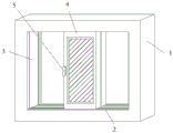
FIG. 1 is a schematic diagram of the basic structure of the present invention;
FIG. 2 is a schematic view of the buffering mechanism of the present invention;
FIG. 3 is a schematic view of the structure of the window body of the present invention;
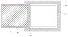
fig. 4 is the schematic view of the working state of the window body of the present invention.
Detailed Description
The technical solutions in the embodiments of the present invention will be described clearly and completely with reference to the accompanying drawings in the embodiments of the present invention, and it is obvious that the described embodiments are only some embodiments of the present invention, not all embodiments. Based on the embodiments in the present invention, all other embodiments obtained by a person skilled in the art without creative work belong to the protection scope of the present invention.
In the description of the present invention, it is to be understood that the terms "center", "longitudinal", "lateral", "length", "width", "thickness", "upper", "lower", "front", "rear", "left", "right", "vertical", "horizontal", "top", "bottom", "inner", "outer", "clockwise", "counterclockwise", and the like indicate orientations or positional relationships based on the orientations or positional relationships shown in the drawings, and are only for convenience of description and to simplify the description, but do not indicate or imply that the device or element referred to must have a particular orientation, be constructed and operated in a particular orientation, and therefore should not be construed as limiting the present invention.
As shown in fig. 1-4, the utility model provides a sliding window, including window frame 1, two sets of slide rails 2 have transversely been seted up to the inside of window frame 1, the equal sliding connection in inside of slide rail 2 has window body 4, the equal fixedly connected with buffer gear 3 of both sides inner wall of window frame 1, window body 4 includes sliding connection in the inside push-and-pull frame 401 of slide rail 2, standing groove 402 has been seted up to the outside on the inside top side of push-and-pull frame 401, the inside fixed mounting of standing groove 402 has micro motor 403, micro motor 403's output fixedly connected with bull stick 404, the other end of bull stick 404 rotates with the inside bottom side of push-and-pull frame 401 and is connected, the surface fixed connection of bull stick 404 has glass frame 405, the inside fixed connection of glass frame 405 has first glass 406, glass frame 405 is located the inside of push-and-pull frame 401; at first can remove the position of two sets of window bodies 4 through pulling window body 4 to adjust to suitable draught area size, if need bigger draught area, remove window body 4 to suitable position, start micro motor 403 and rotate bull stick 404 and make glass frame 405 rotate to suitable angle, can make draught area bigger.
The rear end of the interior of the push-pull frame 401 is fixedly connected with a rain shielding frame 407 corresponding to the first glass 406; the rain shielding frame 407 is set up to prevent rain water from falling into the room when the glass frame 405 is inside the push-pull frame 401.
The buffer mechanism 3 comprises a spring 301 fixedly connected with the inner wall of the window frame 1, and the other end of the spring 301 is fixedly connected with a buffer plate 302; when window body 4 removed the avris one side of window body 4 can contradict with buffer board 302, then utilize spring 301 to cushion flexible, start the absorbing effect of buffering, prolonged window body 4's life.
The outer side of the buffer plate 302 is fixedly connected with a sleeve 303, the inner part of the sleeve 303 is connected with a connecting rod 304 in a sliding manner, the other end of the connecting rod 304 is fixedly connected with the inner wall of the window frame 1, and the sleeve 303 and the connecting rod 304 are positioned inside the spring 301; the movement of the buffer plate 302 is made more smooth by the provision of the sleeve 303 and the connecting rod 304.
The two groups of window bodies 4 are fixedly connected with pull blocks 5, and the outer surfaces of the pull blocks 5 are provided with anti-skid grains; the pull block 5 with the anti-skid lines is arranged, so that a user can push and pull the window body 4 conveniently.
The working principle is as follows: the user draws 5 removal window bodies 4 through the pulling, one side of window body 4 can contradict with buffer board 302 when moving the avris, then utilize spring 301 to cushion telescopically, start the absorbing effect of buffering, the life of window body 4 has been prolonged, at first, can remove the position of two sets of window bodies 4 through pulling window body 4, thereby adjust to suitable draught area size, if need bigger draught area, remove window body 4 to suitable position, start micro motor 403 and rotate bull stick 404 and make glass frame 405 rotate to suitable angle, can make draught area bigger.
The foregoing shows and describes the general principles, essential features, and advantages of the invention. It should be understood by those skilled in the art that the present invention is not limited by the above embodiments, and the description in the above embodiments and the description is only preferred examples of the present invention, and is not intended to limit the present invention, and that the present invention can have various changes and modifications without departing from the spirit and scope of the present invention, and these changes and modifications all fall into the scope of the claimed invention. The scope of the invention is defined by the appended claims and equivalents thereof.
Claims (5)
1. A sliding window, comprising a window frame (1), characterized in that: the window comprises a window frame (1), wherein two groups of sliding rails (2) are transversely arranged in the window frame (1), window bodies (4) are slidably connected in the sliding rails (2), buffer mechanisms (3) are fixedly connected to the inner walls of the two sides of the window frame (1), each window body (4) comprises a push-pull frame (401) slidably connected in the sliding rail (2), a placing groove (402) is formed in the outer side of the top side in the push-pull frame (401), a micro motor (403) is fixedly arranged in the placing groove (402), an output end of the micro motor (403) is fixedly connected with a rotating rod (404), the other end of the rotating rod (404) is rotatably connected with the bottom side in the push-pull frame (401), a glass frame (405) is fixedly connected to the outer surface of the rotating rod (404), first glass (406) is fixedly connected in the glass frame (405), and the glass frame (405) is located in the push-pull frame (401).
2. A sliding window according to claim 1, characterised in that: the rear end of the inner part of the push-pull frame (401) is fixedly connected with a rain shielding frame (407) corresponding to the first glass (406).
3. A sliding window according to claim 1, characterised in that: buffer gear (3) including with window frame (1) inner wall fixed connection's spring (301), the other end fixedly connected with buffer board (302) of spring (301).
4. A sliding window according to claim 3, characterised in that: the outside fixedly connected with sleeve (303) of buffer board (302), the inside sliding connection of sleeve (303) has connecting rod (304), the other end and window frame (1) inner wall fixed connection of connecting rod (304), sleeve (303) and connecting rod (304) are located the inside of spring (301).
5. A sliding window according to claim 1, characterised in that: two sets of equal fixedly connected with draws piece (5) on window body (4), the surface of drawing piece (5) has seted up anti-skidding line.
Priority Applications (1)
| Application Number | Priority Date | Filing Date | Title |
|---|---|---|---|
| CN202221982029.0U CN218716191U (en) | 2022-07-29 | 2022-07-29 | Sliding window |
Applications Claiming Priority (1)
| Application Number | Priority Date | Filing Date | Title |
|---|---|---|---|
| CN202221982029.0U CN218716191U (en) | 2022-07-29 | 2022-07-29 | Sliding window |
Publications (1)
| Publication Number | Publication Date |
|---|---|
| CN218716191U true CN218716191U (en) | 2023-03-24 |
Family
ID=85628378
Family Applications (1)
| Application Number | Title | Priority Date | Filing Date |
|---|---|---|---|
| CN202221982029.0U Active CN218716191U (en) | 2022-07-29 | 2022-07-29 | Sliding window |
Country Status (1)
| Country | Link |
|---|---|
| CN (1) | CN218716191U (en) |
-
2022
- 2022-07-29 CN CN202221982029.0U patent/CN218716191U/en active Active
Similar Documents
| Publication | Publication Date | Title |
|---|---|---|
| CN201377255Y (en) | High-sealing sliding window | |
| CN214062732U (en) | Aluminum alloy door and window convenient to it is clean | |
| CN210685699U (en) | Intelligent control door and window | |
| CN213627240U (en) | Multifunctional sliding bay window capable of being opened into balcony | |
| CN213627226U (en) | Plastic-steel sliding window | |
| CN212026882U (en) | Combined building structure convenient for lighting | |
| CN211646880U (en) | Energy-saving glass curtain wall | |
| CN213175317U (en) | Household self-cleaning energy-saving window | |
| CN212614341U (en) | Anti-corrosion bridge-cut-off sliding window | |
| CN218479737U (en) | Window body structure of plastic steel sliding window | |
| CN206829929U (en) | A kind of road alloy energy-saving sliding window of long-life | |
| CN222615149U (en) | Prevent scraping drift window that bumps | |
| CN211818883U (en) | Electric door and window opening and closing device | |
| CN214463587U (en) | Movable frame body for aluminum alloy movable door and window | |
| CN214786975U (en) | Civil air defense door with multifunctional window | |
| CN217080151U (en) | Window convenient to clearance | |
| CN213234837U (en) | Passive door and window capable of insulating sound and reducing noise | |
| CN218563381U (en) | Auxiliary stress rod piece for window | |
| CN218029840U (en) | High-sealing energy-saving aluminum alloy door and window | |
| CN222376294U (en) | Deformable landing window | |
| CN220747793U (en) | Movable outdoor space capsule | |
| CN220747953U (en) | Window opening distance adjusting device | |
| CN214741004U (en) | Indoor roller shutter type shading and windproof flexible curtain | |
| CN218815987U (en) | Door and window capable of being overturned and cleaned | |
| CN220285616U (en) | Noise-eliminating high-airtight electric double-layer rainproof shutter |
Legal Events
| Date | Code | Title | Description |
|---|---|---|---|
| GR01 | Patent grant | ||
| GR01 | Patent grant |