CN218697884U - Barrel positioner - Google Patents
Barrel positioner Download PDFInfo
- Publication number
- CN218697884U CN218697884U CN202222623467.4U CN202222623467U CN218697884U CN 218697884 U CN218697884 U CN 218697884U CN 202222623467 U CN202222623467 U CN 202222623467U CN 218697884 U CN218697884 U CN 218697884U
- Authority
- CN
- China
- Prior art keywords
- positioning device
- positioning
- base
- clamping cylinder
- clamping
- Prior art date
- Legal status (The legal status is an assumption and is not a legal conclusion. Google has not performed a legal analysis and makes no representation as to the accuracy of the status listed.)
- Active
Links
- 238000012423 maintenance Methods 0.000 abstract description 5
- 238000010586 diagram Methods 0.000 description 2
- 238000000034 method Methods 0.000 description 1
- 230000004048 modification Effects 0.000 description 1
- 238000012986 modification Methods 0.000 description 1
Images


Landscapes
- Jigs For Machine Tools (AREA)
Abstract
The utility model relates to a barrel positioner, include: the clamping cylinder drives the clamping block to move radially, the shell of the clamping cylinder is fixedly connected with the base and evenly distributed along the circumferential direction, the positioning block is fixedly connected with the base and evenly distributed along the circumferential direction, and a positioning groove is formed above the positioning block. The utility model discloses a constant head tank of locating piece fixes a position the rotor barrel, presss from both sides tight piece through the die clamping cylinder drive with the rotor barrel clamp tightly, does not need to use the chuck of major diameter to come the clamping rotor barrel, has solved the purchase of major diameter chuck and the higher problem of maintenance cost.
Description
Technical Field
The utility model belongs to the technical field of anchor clamps and specifically relates to a barrel positioner.
Background
The existing large-diameter motor shell is clamped by a large-diameter chuck, the purchase and maintenance cost of the large-diameter chuck is high, and meanwhile, the subsequent maintenance steps are troublesome. And the chuck is required to be adjusted when part of the chucks are clamped every time, so that the clamping is very inconvenient.
SUMMERY OF THE UTILITY MODEL
The utility model aims at solving the above problem, provide a barrel positioner, solved the purchase of major diameter chuck and the higher problem of maintenance cost.
A cartridge positioning device, comprising: base, locating piece, die clamping cylinder and press from both sides tight piece, die clamping cylinder drive presss from both sides tight piece radial movement, die clamping cylinder's casing and base fixed connection evenly arrange along circumference, locating piece and base fixed connection evenly arrange along circumference, be formed with the top on the locating piece and be formed with the constant head tank.
On the basis of the technical scheme, the positioning grooves are arc grooves, all the positioning grooves are divided into a plurality of groups, and the inner diameter and the outer diameter of each group of positioning grooves are equal.
On the basis of the technical scheme, a chamfer or a fillet is formed on one side of the positioning groove, which is far away from the bottom of the groove.
On the basis of the technical scheme, a plurality of bulges are formed on the inner side of the clamping block.
On the basis of the technical scheme, the bulges are round tables or prismatic tables, and all the bulges of one clamping block are arranged in a rectangular array.
On the basis of the technical scheme, the device further comprises a support frame, the support frame is fixedly connected with the base, and the screw penetrates through the positioning block and is in threaded connection with the support frame.
On the basis of the technical scheme, the number of the positioning blocks and the number of the clamping cylinders are 4.
The utility model has the advantages of as follows: the positioning groove through the positioning block positions the rotor barrel, the clamping block is driven by the clamping cylinder to clamp the rotor barrel, a large-diameter chuck is not required to be used for clamping the rotor barrel, and the problem that the purchase and maintenance cost of the large-diameter chuck is high is solved.
Drawings
In order to more clearly illustrate the embodiments of the present invention or the technical solutions in the prior art, the drawings used in the description of the embodiments or the prior art will be briefly described below. It is obvious that the drawing in the following description is only an embodiment of the invention, and that for a person skilled in the art, other embodiments can be derived from the drawing provided without inventive effort.
FIG. 1: the utility model discloses a schematic overlooking structure;
FIG. 2 is a schematic diagram: the cross-sectional structure at A-A in FIG. 1 is schematic;
FIG. 3: a partial enlarged structure schematic diagram at B;
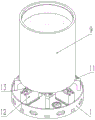
FIG. 4: the three-dimensional structure of the utility model is shown schematically;
FIG. 5: the utility model discloses spatial structure schematic during clamping.
Detailed Description
The invention will be further described with reference to the following figures and examples:
reference will now be made in detail to the embodiments of the present invention, examples of which are illustrated in the accompanying drawings, wherein like reference numerals refer to the same or similar elements or elements having the same or similar functions throughout. The embodiments described below with reference to the drawings are exemplary only for the purpose of explaining the present invention, and should not be construed as limiting the present invention.
In the description of the present invention, it is to be noted that, unless otherwise explicitly specified or limited, the terms "mounted," "connected," and "connected" are to be construed broadly, and may be, for example, fixedly connected, detachably connected, or integrally connected; may be directly connected or indirectly connected through an intermediate. The specific meaning of the above terms in the present invention can be understood in specific cases to those skilled in the art.
In the description of the present invention, it is to be understood that the terms "upper", "lower", "front", "rear", "left", "right", "vertical", "horizontal", "top", "bottom", "inner", "outer", and the like indicate orientations or positional relationships based on those shown in the drawings, and are only for convenience of description and simplification of description, and do not indicate or imply that the device or element referred to must have a particular orientation, be constructed and operated in a particular orientation, and therefore, should not be construed as limiting the present invention.
The first embodiment is as follows:
as shown in fig. 1 to 5, the present embodiment provides a cartridge positioning device including: base 1, locating piece 11, die clamping cylinder 12 and press from both sides tight piece 13, die clamping cylinder 12 drive presss from both sides tight piece 13 radial movement, die clamping cylinder 12's casing and base 1 fixed connection evenly arrange along circumference, locating piece 11 and base 1 fixed connection evenly arrange along circumference, be formed with the top on the locating piece 11 and be formed with constant head tank 110. Wherein radial and circumferential refer to radial and circumferential of the base 1.
On the basis of the technical scheme, the positioning grooves 110 are arc grooves, all the positioning grooves 110 are divided into a plurality of groups, and the inner diameter and the outer diameter of each group of positioning grooves 110 are equal.
On the basis of the above technical solution, a chamfer 111 or a fillet is formed at one side of the positioning groove 110 away from the groove bottom.
On the basis of the above technical solution, a plurality of protrusions 131 are formed inside the clamping block 13.
On the basis of the above technical scheme, the protrusions 131 are truncated cones or truncated pyramids, and all the protrusions 131 of one clamping block 13 are arranged in a rectangular array.
On the basis of the technical scheme, the device further comprises a supporting frame 14, the supporting frame 14 is fixedly connected with the base 1, and a screw penetrates through the positioning block 11 and is in threaded connection with the supporting frame 14.
On the basis of the technical scheme, the number of the positioning blocks 11 and the number of the clamping cylinders 12 are 4. The clamping cylinder 12 is a pneumatic sliding table.
The working principle is as follows:
when the rotor drum body 9 is in work, the rotor drum body 9 is placed into the designated positioning groove 110 by the travelling crane, and the chamfer 111 of the positioning groove 110 plays a guiding role in the placing process. The inner side surface and the outer side surface of the rotor cylinder 9 are respectively attached to the two side surfaces of the positioning groove 110, and then the clamping cylinder 12 drives the clamping block 13 to move towards the direction close to the rotor cylinder 9 until the clamping block 13 clamps and fixes the rotor cylinder 9 relative to the base 1.
Because the positioning grooves 110 on the positioning block 11 are divided into a plurality of groups, the positioning grooves can be adapted to rotor cylinders 9 with different diameters and thicknesses. Because the positioning block 11 can be detached relative to the support frame 14, more rotor cylinders 9 can be accommodated by replacing positioning blocks 11 with different diameters.
The present invention has been described above by way of example, but the present invention is not limited to the above-mentioned embodiments, and any modification or variation based on the present invention is within the scope of the present invention.
Claims (7)
1. A cartridge positioning device, comprising: base (1), locating piece (11), die clamping cylinder (12) and press from both sides tight piece (13), die clamping cylinder (12) drive presss from both sides tight piece (13) radial movement, the casing and base (1) fixed connection of die clamping cylinder (12) evenly arrange along circumference, locating piece (11) and base (1) fixed connection evenly arrange along circumference, be formed with the top on locating piece (11) and be formed with constant head tank (110).
2. A cartridge positioning device as defined in claim 1, wherein: the positioning grooves (110) are arc grooves, all the positioning grooves (110) are divided into a plurality of groups, and the inner diameter and the outer diameter of each group of positioning grooves (110) are equal.
3. A cartridge positioning device according to claim 2, wherein: and a chamfer (111) or a fillet is formed on one side of the positioning groove (110) far away from the groove bottom.
4. A cartridge positioning device according to claim 1, wherein: a plurality of protrusions (131) are formed on the inner side of the clamping block (13).
5. A cartridge positioning device as claimed in claim 4, wherein: the bulges (131) are round tables or prismatic tables, and all the bulges (131) of one clamping block (13) are arranged in a rectangular array.
6. A cartridge positioning device as defined in claim 1, wherein: the positioning device is characterized by further comprising a supporting frame (14), wherein the supporting frame (14) is fixedly connected with the base (1), and a screw penetrates through the positioning block (11) to be in threaded connection with the supporting frame (14).
7. A cartridge positioning device as defined in claim 1, wherein: the number of the positioning blocks (11) and the number of the clamping cylinders (12) are 4.
Priority Applications (1)
| Application Number | Priority Date | Filing Date | Title |
|---|---|---|---|
| CN202222623467.4U CN218697884U (en) | 2022-09-30 | 2022-09-30 | Barrel positioner |
Applications Claiming Priority (1)
| Application Number | Priority Date | Filing Date | Title |
|---|---|---|---|
| CN202222623467.4U CN218697884U (en) | 2022-09-30 | 2022-09-30 | Barrel positioner |
Publications (1)
| Publication Number | Publication Date |
|---|---|
| CN218697884U true CN218697884U (en) | 2023-03-24 |
Family
ID=85639187
Family Applications (1)
| Application Number | Title | Priority Date | Filing Date |
|---|---|---|---|
| CN202222623467.4U Active CN218697884U (en) | 2022-09-30 | 2022-09-30 | Barrel positioner |
Country Status (1)
| Country | Link |
|---|---|
| CN (1) | CN218697884U (en) |
-
2022
- 2022-09-30 CN CN202222623467.4U patent/CN218697884U/en active Active
Similar Documents
| Publication | Publication Date | Title |
|---|---|---|
| CN110153615A (en) | A kind of annular solder equipment and its application method | |
| CN209850201U (en) | Butt spot welding tool clamp for water heater enamel inner container barrel body end socket | |
| CN218363510U (en) | Positioning mechanism for part machining clamp | |
| CN102699715B (en) | Clamping device | |
| CN202212604U (en) | Novel self-centering four-claw clamp | |
| CN212683078U (en) | Automatic screw feeding device | |
| CN219633086U (en) | Four-axis hydraulic clamp for milling surface and drilling | |
| CN213003987U (en) | Pneumatic clamp for plate body machining | |
| CN220480954U (en) | Three-positioning self-centering clamping device | |
| CN211516769U (en) | Quick clamping device for machine manufacturing | |
| CN216176740U (en) | Cage positioning and clamping tool | |
| CN216298963U (en) | Vertical honing automatic clamp | |
| CN217750537U (en) | Clamping and positioning tool in flywheel shell | |
| CN211161979U (en) | Chuck structure with rotary oil cylinder | |
| CN214351672U (en) | Vertical honing machine convenient to feed | |
| CN210306893U (en) | Numerical control machine tool machining positioning fixture | |
| CN219336020U (en) | Double-layer rotating curved surface body clamp | |
| CN219853315U (en) | Metal processing clamp convenient to operate | |
| CN217432748U (en) | Combined clamp for processing shell | |
| CN223997908U (en) | Double-station hydraulic clamping tool | |
| CN219598575U (en) | Laser welding fixture for thin-wall part of aircraft engine in blocks | |
| CN220240782U (en) | Anchor clamps are used in CNC processing | |
| CN218461542U (en) | High-precision clamping jig | |
| CN213795280U (en) | Auxiliary fixing jig | |
| CN218504446U (en) | Mould processing positioner |
Legal Events
| Date | Code | Title | Description |
|---|---|---|---|
| GR01 | Patent grant | ||
| GR01 | Patent grant |