CN218696189U - Tapping machine for processing preposed filter screen - Google Patents
Tapping machine for processing preposed filter screen Download PDFInfo
- Publication number
- CN218696189U CN218696189U CN202222844178.7U CN202222844178U CN218696189U CN 218696189 U CN218696189 U CN 218696189U CN 202222844178 U CN202222844178 U CN 202222844178U CN 218696189 U CN218696189 U CN 218696189U
- Authority
- CN
- China
- Prior art keywords
- filter screen
- plate
- sheet metal
- threaded rod
- installation
- Prior art date
- Legal status (The legal status is an assumption and is not a legal conclusion. Google has not performed a legal analysis and makes no representation as to the accuracy of the status listed.)
- Expired - Fee Related
Links
Images



Landscapes
- Filtering Materials (AREA)
Abstract
The utility model discloses a tapping machine of leading filter screen processing, including mount pad, deflector and installation pole, one side of installation pole is run through movable mounting and is had the movable plate, the bracing piece is installed to the one end of movable plate, a plurality of second installation pieces are installed at the top of bracing piece, the inboard movable mounting of second installation piece has the rotation wheel, the spring is installed at the top of bracing piece, the clamp plate is installed to the one end of spring. The utility model discloses an adjust the distance between two bracing pieces and make the bracing piece can support the not sheet metal of equidimension, the pulling clamp plate makes the sheet metal be located the clamp plate below, make the clamp plate can exert pressure to the sheet metal, and then guarantee the stability when the sheet metal is trompil, then extrude the sheet metal through the gag lever post, make the sheet metal keep parallel with the gag lever post, and then make the hole of opening on the sheet metal keep neat, frictional force when can reducing the removal sheet metal through rotating the wheel, save physical power.
Description
Technical Field
The utility model relates to a filter screen processing technology field specifically is a tapping machine of leading filter screen processing.
Background
Need use filter screen among the water treatment system, some filter screen are columniform, columniform filter screen is rolled up the filter screen of film shape and welds and form, consequently, it all punches to film shape filter screen to filter screen, it generally punches to use laser-beam drilling machine to punch a large amount of holes on the sheet metal, laser-beam drilling machine's the efficient of punching, a large amount of heavier sheet metal of staff's transport is to the support position of puncher, and can consume a large amount of physical power to the in-process that adjusts the sheet metal, cause fatigue, and then influence work efficiency, consequently, need a tapping machine convenient to adjust the sheet metal position.
The existing tapping machine has the defects that:
1. patent document CN213561345U discloses a numerical control tapping machine, "including workstation, supporting legs, dust collection box, play tuber pipe, sweeps collection net, air exhauster, filter screen, active carbon adsorption net, first step motor, first lead screw, slider, backup pad, stand, rack, mounting panel, second step motor, second lead screw, install bin, cylinder, piston rod, driving motor, tool bit, mount and hair-dryer, its characterized in that: the utility model discloses a workstation, including workstation bottom four corners, workstation bottom four corners all welds the supporting legs, the workstation bottom is provided with the dust collection box, be provided with the sweeps in the middle of the dust collection box inner wall and collect the net, the air exhauster is installed to dust collection box inner wall bottom one end, the welding of dust collection box outer wall one side bottom has out the tuber pipe, and air exhauster one end and play tuber union coupling, workstation top one side corresponds both ends and all is fixed with first step motor, the utility model discloses, the trompil is convenient, can collect the sweeps, protects the environment, "with the utility model discloses compare, the unable position of adjusting the support frame of this equipment can't support the sheet metal of different width, and the staff removes also more extravagant physical power to heavier sheet metal when placing the sheet metal on the rack.
SUMMERY OF THE UTILITY MODEL
An object of the utility model is to provide a tapping machine of leading filter screen processing to solve the problem that proposes among the above-mentioned background art.
In order to achieve the above object, the utility model provides a following technical scheme: a tapping machine for processing a front-mounted filter screen comprises a mounting seat, a guide plate and a mounting rod, wherein the guide plate is mounted at the top of the mounting seat, and a first mounting plate is mounted on one side of the guide plate;
one side of installation pole runs through movable mounting and has the movable plate, the bracing piece is installed to the one end of movable plate, a plurality of second installation pieces are installed at the top of bracing piece, the inboard movable mounting of second installation piece has the rotation wheel, the spring is installed at the top of bracing piece, the clamp plate is installed to the one end of spring.
Preferably, first support column is installed to the bottom symmetry of mount pad, and a plurality of stoppers are installed to the top symmetry of mount pad, and the stopper is located the outside of movable plate, and first installation piece is installed at the top of mount pad, and the back mounted of mount pad has the cooling bath, and the second support column is installed to the bottom symmetry of cooling bath.
Preferably, a support block is mounted on the top of the guide plate.
Preferably, a first motor is installed at the top of the first installation plate, a first threaded rod is installed at the output end of the first motor, one end of the first threaded rod penetrates through one side of the support block, a first moving block is installed on the outer side of the first threaded rod, and a guide frame is installed at the bottom of the first moving block.
Preferably, the mounting box is installed in the front of guide frame, and the internally mounted of mounting box has the second motor, and the second threaded rod is installed to the output of second motor, and the back inner wall of guide frame is run through to the one end of second threaded rod.
Preferably, a second moving block is installed on the outer side of the second threaded rod, an air cylinder is installed inside the second moving block, a second installation plate is installed at the output end of the air cylinder, and a laser gun is installed at the bottom of the second installation plate.
Preferably, the top of bracing piece is installed the gag lever post, and the top of installation pole is run through and is installed the third threaded rod.
Preferably, the top of clamp plate is installed thermal-insulated cotton pad, and the handle is installed at the top of clamp plate, and the outside of handle is installed first thermal-insulated cotton cover.
Preferably, the front surface of the first mounting block is provided with a push rod in a penetrating and movable manner, and the outer side of the push rod is provided with a second heat insulation cotton sleeve.
Preferably, the mounting ring is installed in the outside of push rod, and the top of mounting ring is run through and is installed the fourth threaded rod, and the back mounted of mounting ring has the ejector pad, and the cotton cover of third thermal-insulated is installed in the outside of ejector pad.
Compared with the prior art, the beneficial effects of the utility model are that:
1. the utility model discloses an adjust the distance between two bracing pieces and make the bracing piece can support the not sheet metal of equidimension, the pulling clamp plate makes the sheet metal be located the clamp plate below, make the clamp plate can exert pressure to the sheet metal, and then guarantee the stability when the sheet metal is trompil, then extrude the sheet metal through the gag lever post, make the sheet metal keep parallel with the gag lever post, and then make the hole of opening on the sheet metal keep neat, frictional force when can reducing the removal sheet metal through rotating the wheel, save physical power, make the tapping machine can support the sheet metal of different width, and can reduce the frictional force when the sheet metal removes, reduce the physical power when the staff adjusts the removal sheet metal.
2. The utility model discloses a promote the push rod then and make the ejector pad promote the good filter screen of processing backward, filter screen removes inside the cooling bath, the heat on the filter screen is walked by the inside hosepipe of cooling bath, and then carry out rapid cooling to filter screen, stability when the push rod removes can be guaranteed to first installation piece, rocking phenomenon about can not appearing when making the staff promote filter screen, stability when guaranteeing to promote filter screen, can remove the fixed to the push rod through rotating the fourth threaded rod, the convenience is changed ejector pad and push rod, make the tapping machine can promote the stable ejection bracing piece with the sheet metal of push rod, avoid the filter screen that the staff manual handling processed, reduce the possibility that the staff scalded, and the convenience is changed push rod and ejector pad.
Drawings
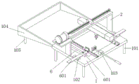
Fig. 1 is a perspective view of the present invention;
fig. 2 is a schematic diagram of the structure of the guide plate of the present invention;
FIG. 3 is a schematic structural view of the guide frame of the present invention;
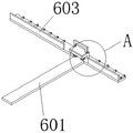
fig. 4 is a schematic view of the structure of the support rod of the present invention;
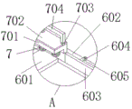
fig. 5 is a schematic structural view of the position a of the present invention;
fig. 6 is a schematic view of the push rod structure of the present invention.
In the figure: 1. a mounting seat; 101. a first support column; 102. a limiting block; 103. a first mounting block; 104. a cooling tank; 105. a second support column; 2. a guide plate; 201. a support block; 3. a first mounting plate; 301. a first motor; 302. a first threaded rod; 303. a first moving block; 304. a guide frame; 4. mounting a box; 401. a second motor; 402. a second threaded rod; 5. a second moving block; 501. a cylinder; 502. a second mounting plate; 503. a laser gun; 6. mounting a rod; 601. moving the plate; 602. a support bar; 603. a limiting rod; 604. a second mounting block; 605. a rotating wheel; 606. a third threaded rod; 7. a spring; 701. pressing a plate; 702. a heat insulating cotton pad; 703. a handle; 704. a first heat insulating cotton sleeve; 8. a push rod; 801. a second heat insulating cotton sleeve; 9. a mounting ring; 901. a fourth threaded rod; 902. a push block; 903. and a third heat insulation cotton sleeve.
Detailed Description
The technical solutions in the embodiments of the present invention will be described clearly and completely with reference to the accompanying drawings in the embodiments of the present invention, and it is obvious that the described embodiments are only some embodiments of the present invention, not all embodiments. Based on the embodiments in the present invention, all other embodiments obtained by a person skilled in the art without creative work belong to the protection scope of the present invention.
In the description of the present invention, it should be noted that the terms "upper", "lower", "inner", "outer", "front end", "rear end", "both ends", "one end", "the other end" and the like indicate orientations or positional relationships based on the orientations or positional relationships shown in the drawings, and are only for convenience of description and simplification of description, but do not indicate or imply that the device or element to which the reference is made must have a specific orientation, be constructed in a specific orientation, and be operated, and thus, should not be construed as limiting the present invention. Furthermore, the terms "first" and "second" are used for descriptive purposes only and are not to be construed as indicating or implying relative importance.
In the description of the present invention, it is to be noted that, unless otherwise explicitly specified or limited, the terms "mounted," "disposed," "connected," and the like are to be construed broadly, and for example, "connected" may be either fixedly connected or detachably connected, or integrally connected; can be mechanically or electrically connected; they may be connected directly or indirectly through intervening media, or they may be interconnected between two elements. The specific meaning of the above terms in the present invention can be understood as a specific case by those skilled in the art.
Referring to fig. 1, fig. 2 and fig. 3, the present invention provides an embodiment: a tapping machine for processing a front-mounted filter screen;
the device comprises an installation seat 1, a guide plate 2, a first installation plate 3, an installation box 4 and a second moving block 5, wherein first supporting columns 101 are symmetrically installed at the bottom of the installation seat 1, a plurality of limiting blocks 102 are symmetrically installed at the top of the installation seat 1, the limiting blocks 102 are located on the outer side of a moving plate 601, a first installation block 103 is installed at the top of the installation seat 1, a cooling groove 104 is installed at the back of the installation seat 1, second supporting columns 105 are symmetrically installed at the bottom of the cooling groove 104, the installation seat 1 can provide installation positions for other parts of the device, so that the other parts of the device can be installed, the first supporting columns 101 can support the installation seat 1, the limiting blocks 102 play a limiting role, the moving plate 601 can be prevented from inclining, the moving plate 601 can be enabled to move in parallel, water can be injected into the cooling groove 104, and the temperature of the perforated filtering screen can be further reduced, the second supporting column 105 can provide support for the cooling groove 104, the guide plate 2 is installed at the top of the mounting base 1, the supporting block 201 is installed at the top of the guide plate 2, the guide plate 2 can provide guide for the first moving block 303 and can prevent the first moving block 303 from rotating, the supporting block 201 can provide support for the first threaded rod 302 and prevent the first threaded rod 302 from being bent, the first mounting plate 3 is installed at one side of the guide plate 2, the first motor 301 is installed at the top of the first mounting plate 3, the first threaded rod 302 is installed at the output end of the first motor 301, one end of the first threaded rod 302 penetrates through one side of the supporting block 201, the first moving block 303 is installed at the outer side of the first threaded rod 302, the guide frame 304 is installed at the bottom of the first moving block 303, the first mounting plate 3 can provide a mounting position for the first motor 301, and the first motor 301 can convert electric energy into kinetic energy, thereby can drive first threaded rod 302 and rotate, first threaded rod 302 can drive first movable block 303 through rotating and remove about, first movable block 303 can indirectly drive laser gun 503 and remove about through removing about and remove, make laser gun 503 punch about the sheet metal, guide frame 304 plays the effect of direction, can provide the guide function to second movable block 5, can avoid second movable block 5 rotatory simultaneously, install box 4 in the front of guide frame 304, the internally mounted of installation box 4 has second motor 401, second threaded rod 402 is installed to the output of second motor 401, and the one end of second threaded rod 402 runs through the back inner wall of guide frame 304, installation box 4 plays the effect of installing second motor 401, second motor 401 can convert the electric energy into kinetic energy, thereby can drive second threaded rod 402 and rotate, second threaded rod 402 can drive second movable block 5 through rotating and carry out the back-and-forth movement, second movable block 5 is installed to the outside of second threaded rod 402, the internally mounted of second movable block 5 has cylinder 501, the output of cylinder is installed second mounting panel 502, the bottom mounting panel 503 is installed to the bottom of second threaded rod 502, second threaded rod 502 can drive the laser gun 503 and can drive the high temperature gun 503 and carry out the effect of punching to the laser gun and can drive the laser gun 503 and carry out the high temperature punching to the laser gun.
Referring to fig. 1, 4, 5 and 6, the present invention provides an embodiment: a tapping machine for processing a front-mounted filter screen;
the device comprises an installation rod 6, a spring 7, a push rod 8 and an installation ring 9, wherein a movable plate 601 penetrates through one side of the installation rod 6 and is movably installed, one end of the movable plate 601 is provided with a support rod 602, the top of the support rod 602 is provided with a limiting rod 603, the top of the support rod 602 is provided with a plurality of second installation blocks 604, the inner sides of the second installation blocks 604 are movably provided with rotating wheels 605, the top of the installation rod 6 is provided with a third threaded rod 606 in a penetrating manner, the installation rod 6 can provide an installation position for the movable plate 601 and simultaneously can prevent the movable plate 601 from inclining so that the movable plate 601 can move in parallel, the movable plate 601 can drive the support rod 602 to move left and right through movement, the support rod 602 can support thin plates with different widths through moving left and right, the limiting rod 603 can extrude the thin plates so that the thin plates can be kept horizontal with the limiting rod 603 and prevent the thin plates from inclining, the second installation blocks 604 can provide installation positions for the rotating wheels 605, the rotating wheel 605 can be installed, the rotating wheel 605 can support the thin plate, the friction force when the thin plate moves is reduced, the physical force consumed when an operator moves the thin plate is reduced, the third threaded rod 606 can extrude and fix the moving plate 601 through rotation to maintain the stability of the moving plate 601, the spring 7 is installed at the top of the supporting rod 602, the pressing plate 701 is installed at one end of the spring 7, the heat insulation cotton pad 702 is installed at the top of the pressing plate 701, the handle 703 is installed at the top of the pressing plate 701, the first heat insulation cotton sleeve 704 is installed at the outer side of the handle 703, the spring 7 can provide elastic force, so that pulling force can be provided for the pressing plate 701, the pressure of the pressing plate 701 on the thin plate is larger, the stability of the thin plate on the rotating wheel 605 can be better ensured, the thin plate is prevented from moving, and the stability of punching the thin plate can be ensured by pressing the pressing plate 701, the heat insulation cotton pad 702 plays a role in heat insulation, heat transmitted by the thin plate is isolated, the situation that the hands of a worker are directly contacted with the pressing plate 701 to cause scalding can be avoided, the handle 703 can provide a holding position for the worker to facilitate the worker to lift the pressing plate 701, the first heat insulation cotton sleeve 704 plays a role in heat insulation, the situation that the hands of the worker are scalded by the heat on the handle 703 can be avoided, the push rod 8 is movably installed on the front side of the first installation block 103 in a penetrating mode, the second heat insulation cotton sleeve 801 is installed on the outer side of the push rod 8, the push rod 8 can drive the push block 902 to move through moving, meanwhile, the stability of the push rod 8 in moving can be kept through moving inside the first installation block 103 through the push rod 8, and inclination of the push rod 8 in pushing the thin plate is avoided, second thermal-insulated cotton cover 801 can completely cut off the heat on the push rod 8, reduce the possibility that staff's hand was scalded, collar 9 is installed in the outside of push rod 8, collar 9's top is run through and is installed fourth threaded rod 901, collar 9's back mounted has ejector pad 902, third thermal-insulated cotton cover 903 is installed in the outside of ejector pad 902, collar 9 plays the effect of connecting push rod 8 and ejector pad 902, make ejector pad 902 can remove along with push rod 8, fourth threaded rod 901 can extrude push rod 8 fixedly through rotating, guarantee the stability that collar 9 and push rod 8 are connected, ejector pad 902 plays the effect that promotes the sheet metal, it causes the scald to avoid staff's manual promotion sheet metal, the heat of third thermal-insulated cotton cover 903 can completely cut off the sheet metal, reduce the heating of sheet metal to ejector pad 902.
The working principle is as follows: before using the tapping machine of leading filter screen processing, whether the tapping machine of this leading filter screen processing has the problem that influences the use should be examined earlier, adjust the distance between two bracing pieces 602 according to the width of sheet metal and make bracing piece 602 can support the sheet metal of equidimension not, pulling clamp plate 701 makes the sheet metal be located clamp plate 701 below, make clamp plate 701 can exert pressure to the sheet metal, and then guarantee the stability when the sheet metal is trompiled, then extrude the sheet metal through gag lever post 603, make the sheet metal can keep parallel with gag lever post 603, and then make the hole of opening on the sheet metal keep neat, start laser gun 503 and carry out the trompil operation to the sheet metal, drive laser gun 503 through first motor 301 and carry out left and right sides trompil to the sheet metal, drive laser gun 503 through second motor 401 and carry out front and back punching to the sheet metal, after being filled up the hole on the sheet metal, the operation of punching is accomplished, after, promote push rod 8 makes ejector pad 902 promote the good filter screen who processes to move backward, filter screen moves inside 104, the heat on the filter screen is walked away by the inside of cooling tank 104, and can guarantee the stability when the push rod 103 can not promote the stability when the staff's the filter screen and can not appear and rock.
It is obvious to a person skilled in the art that the invention is not restricted to details of the above-described exemplary embodiments, but that it can be implemented in other specific forms without departing from the spirit or essential characteristics of the invention. The present embodiments are therefore to be considered in all respects as illustrative and not restrictive, the scope of the invention being indicated by the appended claims rather than by the foregoing description, and all changes which come within the meaning and range of equivalency of the claims are therefore intended to be embraced therein, and any reference signs in the claims are not intended to be construed as limiting the claim concerned.
Claims (10)
1. The utility model provides a tapping machine of leading filter screen processing, includes mount pad (1), deflector (2) and installation pole (6), its characterized in that: a guide plate (2) is mounted at the top of the mounting seat (1), and a first mounting plate (3) is mounted on one side of the guide plate (2);
one side of installation pole (6) runs through movable mounting and has movable plate (601), bracing piece (602) are installed to the one end of movable plate (601), a plurality of second installation pieces (604) are installed at the top of bracing piece (602), the inboard movable mounting of second installation piece (604) has rotating wheel (605), spring (7) are installed at the top of bracing piece (602), clamp plate (701) are installed to the one end of spring (7).
2. The tapping machine for pre-filter screen processing as claimed in claim 1, wherein: first support column (101) are installed to the bottom symmetry of mount pad (1), and a plurality of stopper (102) are installed to the top symmetry of mount pad (1), and stopper (102) are located the outside of movable plate (601), and first installation piece (103) are installed at the top of mount pad (1), and the back mounted of mount pad (1) has cooling tank (104), and second support column (105) are installed to the bottom symmetry of cooling tank (104).
3. The trompil machine of a pre-filter screen process of claim 1, characterized in that: and the top of the guide plate (2) is provided with a supporting block (201).
4. The trompil machine of a pre-filter screen process of claim 1, characterized in that: the supporting block is characterized in that a first motor (301) is installed at the top of the first installation plate (3), a first threaded rod (302) is installed at the output end of the first motor (301), one end of the first threaded rod (302) penetrates through one side of the supporting block (201), a first moving block (303) is installed on the outer side of the first threaded rod (302), and a guide frame (304) is installed at the bottom of the first moving block (303).
5. The pre-filter screen processed hole opener according to claim 4, characterized in that: the utility model discloses a lead frame, including guide frame (304), the front of guide frame (304) is installed mounting box (4), and the internally mounted of mounting box (4) has second motor (401), and second threaded rod (402) are installed to the output of second motor (401), and the back inner wall of guide frame (304) is run through to the one end of second threaded rod (402).
6. The tapping machine for pre-filter screen processing as claimed in claim 5, wherein: a second moving block (5) is installed on the outer side of the second threaded rod (402), an air cylinder (501) is installed inside the second moving block (5), a second mounting plate (502) is installed at the output end of the air cylinder (501), and a laser gun (503) is installed at the bottom of the second mounting plate (502).
7. The trompil machine of a pre-filter screen process of claim 1, characterized in that: and a limiting rod (603) is installed at the top of the supporting rod (602), and a third threaded rod (606) is installed at the top of the installing rod (6) in a penetrating manner.
8. The tapping machine for pre-filter screen processing as claimed in claim 1, wherein: thermal-insulated cotton pad (702) is installed at the top of clamp plate (701), and handle (703) are installed at the top of clamp plate (701), and first thermal-insulated cotton cover (704) are installed to the outside of handle (703).
9. The tapping machine for pre-filter screen processing as claimed in claim 2, wherein: the front surface of the first mounting block (103) is provided with a push rod (8) in a penetrating and movable mode, and a second heat insulation cotton sleeve (801) is mounted on the outer side of the push rod (8).
10. The pre-filter screen finishing tapping machine of claim 9, wherein: the outside of push rod (8) is installed collar (9), and the top of collar (9) is run through and is installed fourth threaded rod (901), and the back mounted of collar (9) has ejector pad (902), and the cotton cover of third thermal-insulated (903) is installed in the outside of ejector pad (902).
Priority Applications (1)
| Application Number | Priority Date | Filing Date | Title |
|---|---|---|---|
| CN202222844178.7U CN218696189U (en) | 2022-10-27 | 2022-10-27 | Tapping machine for processing preposed filter screen |
Applications Claiming Priority (1)
| Application Number | Priority Date | Filing Date | Title |
|---|---|---|---|
| CN202222844178.7U CN218696189U (en) | 2022-10-27 | 2022-10-27 | Tapping machine for processing preposed filter screen |
Publications (1)
| Publication Number | Publication Date |
|---|---|
| CN218696189U true CN218696189U (en) | 2023-03-24 |
Family
ID=85593540
Family Applications (1)
| Application Number | Title | Priority Date | Filing Date |
|---|---|---|---|
| CN202222844178.7U Expired - Fee Related CN218696189U (en) | 2022-10-27 | 2022-10-27 | Tapping machine for processing preposed filter screen |
Country Status (1)
| Country | Link |
|---|---|
| CN (1) | CN218696189U (en) |
-
2022
- 2022-10-27 CN CN202222844178.7U patent/CN218696189U/en not_active Expired - Fee Related
Similar Documents
| Publication | Publication Date | Title |
|---|---|---|
| CN212122547U (en) | Hardware cutting dust collector | |
| CN221363034U (en) | Numerical control tapping equipment | |
| CN220880963U (en) | Steel pipe cutting machine capable of recycling scraps | |
| CN220740005U (en) | Automatic welding machine for cross bars | |
| CN208304568U (en) | A kind of numerically-controlled machine tool | |
| CN217622495U (en) | Automatic cutting device is used in processing of environmental protection braided bag | |
| CN215237144U (en) | Perforating device is used in manufacturing of high efficiency space flight material | |
| CN213318253U (en) | Quick plasma cutting device of electromechanical accessory | |
| CN210677172U (en) | An aluminum profile cutting device with the function of collecting waste | |
| CN221910106U (en) | High-performance metal water tank production equipment | |
| CN112775261A (en) | Steel plate punching machine tool | |
| CN211539760U (en) | Cutting equipment for plate processing | |
| CN221289202U (en) | Waste recycling device of punching machine | |
| CN220903599U (en) | Panel processingequipment | |
| CN220807723U (en) | Gift box production size cutting device | |
| CN220658917U (en) | Skeleton piercing press | |
| CN216759132U (en) | Waste material removing mechanism for cutting machine | |
| CN218050667U (en) | Crankshaft cutting device | |
| CN213623861U (en) | Cutting equipment with glass residue collecting structure for producing solar glass sheets | |
| CN211072712U (en) | Cutting mechanism for plate processing | |
| CN219076128U (en) | Toughened glass perforating device | |
| CN215786834U (en) | Part drilling device for machining | |
| CN217551902U (en) | Adjustable automatic deviation rectifying steel plate cutting machine | |
| CN221560627U (en) | Numerical control cutting device for numerical control machining | |
| CN220636695U (en) | Panel laser cutting equipment |
Legal Events
| Date | Code | Title | Description |
|---|---|---|---|
| GR01 | Patent grant | ||
| GR01 | Patent grant | ||
| CF01 | Termination of patent right due to non-payment of annual fee |
Granted publication date: 20230324 |
|
| CF01 | Termination of patent right due to non-payment of annual fee |