CN218692728U - Correction tool and correction equipment for battery cover plate connecting piece - Google Patents
Correction tool and correction equipment for battery cover plate connecting piece Download PDFInfo
- Publication number
- CN218692728U CN218692728U CN202222884670.7U CN202222884670U CN218692728U CN 218692728 U CN218692728 U CN 218692728U CN 202222884670 U CN202222884670 U CN 202222884670U CN 218692728 U CN218692728 U CN 218692728U
- Authority
- CN
- China
- Prior art keywords
- block
- cover plate
- correcting
- battery cover
- connecting piece
- Prior art date
- Legal status (The legal status is an assumption and is not a legal conclusion. Google has not performed a legal analysis and makes no representation as to the accuracy of the status listed.)
- Active
Links
Images



Classifications
-
- Y—GENERAL TAGGING OF NEW TECHNOLOGICAL DEVELOPMENTS; GENERAL TAGGING OF CROSS-SECTIONAL TECHNOLOGIES SPANNING OVER SEVERAL SECTIONS OF THE IPC; TECHNICAL SUBJECTS COVERED BY FORMER USPC CROSS-REFERENCE ART COLLECTIONS [XRACs] AND DIGESTS
- Y02—TECHNOLOGIES OR APPLICATIONS FOR MITIGATION OR ADAPTATION AGAINST CLIMATE CHANGE
- Y02E—REDUCTION OF GREENHOUSE GAS [GHG] EMISSIONS, RELATED TO ENERGY GENERATION, TRANSMISSION OR DISTRIBUTION
- Y02E60/00—Enabling technologies; Technologies with a potential or indirect contribution to GHG emissions mitigation
- Y02E60/10—Energy storage using batteries
Landscapes
- Battery Mounting, Suspending (AREA)
Abstract
The utility model provides a battery cover plate connecting piece's correction frock, it includes: the lower die is provided with a sliding groove; the correcting block is positioned in the sliding groove and is connected with the lower die in a sliding manner, and a guide surface is formed at the end part of the correcting block; the connecting plate is positioned on one side of the lower die, and a connecting seat is fixedly connected to the connecting plate; the connecting block is positioned on the connecting seat, and the connecting block is movably connected with the connecting seat; the upper die is positioned at the end part of the connecting block, and the upper die is detachably connected with the connecting block; the driving block is fixedly connected to the connecting seat, and the end part of the driving block is provided with a driving surface; wherein, the driving surface is attached to the guide surface, and the driving block can drive the correction block to slide in the sliding groove. The utility model discloses can effectively improve the correction processing to the connecting piece of battery apron to make the connecting piece of battery apron be in the compliance state, and improve the utilization ratio that takes place deformation cover plate connecting piece.
Description
Technical Field
The utility model relates to a battery production technical field, concretely relates to battery cover plate connecting piece's correction frock and correction equipment.
Background
With the development of related industries of material processing in China, the requirements of processed materials such as plastic, metal, semiconductor and the like are more strict. For defective products in the manufacture of finished products of battery cover plates, the defective products are usually scrapped, and the waste rate is high.
Currently, in the manufacturing process of the battery cover plate, the deformation and bending phenomena of the base plate of the cover plate connecting piece occur. The bent base plate may cause a phenomenon in which the connection member is deflected outward in a splay shape, resulting in an abnormality in the assembly process of the battery. Wherein, the bent substrate is usually processed by scrap or corrected by manual work. The precision of the substrate is generally difficult to ensure by manual correction, and the manual correction is high in labor consumption and low in correction efficiency.
SUMMERY OF THE UTILITY MODEL
In view of the shortcoming of the above prior art, an object of the utility model is to provide a battery cover plate connecting piece's correction frock and correction equipment to improve the current correction effect of battery cover plate's connecting piece relatively poor, and correct the lower problem of efficiency.
In order to realize above-mentioned purpose and other relevant purposes, the utility model provides a battery cover plate connecting piece's correction frock, a serial communication port, include:
the lower die is provided with a sliding groove;
the correcting block is positioned in the sliding groove and is connected with the lower die in a sliding mode, and a guide surface is formed in the end portion of the correcting block;
the connecting plate is positioned on one side of the lower die, and a connecting seat is fixedly connected to the connecting plate;
the connecting block is positioned on the connecting seat, and the connecting block is movably connected with the connecting seat;
the upper die is positioned at the end part of the connecting block, and the upper die is detachably connected with the connecting block; and
the driving block is fixedly connected to the connecting seat, and a driving surface is arranged at the end part of the driving block;
the driving surface is attached to the guide surface, and the driving block can drive the correcting block to slide in the sliding groove.
In an embodiment of the present invention, two sets of the sliding grooves are provided, and two sets of the driving blocks are provided; the driving block and the correcting block positioned in the sliding groove are correspondingly arranged.
The utility model discloses an in the embodiment, still include reset spring, its setting is in the spout, just reset spring's one end is connected revise on the piece, and reset spring's the other end is connected the terminal surface of spout.
In an embodiment of the present invention, the return spring and the driving block are respectively located at two sides of the correcting block.
The utility model discloses an in the embodiment, still include thrust spring, it is located the connecting block with between the connecting seat, just thrust spring's compression direction is located in the direction of motion of connecting block.
In an embodiment of the present invention, the upper mold includes: the bottom plate is fixedly connected to the end face of the connecting block; the two groups of extrusion blocks are arranged, and the extrusion blocks are fixedly connected to the side walls of the connecting blocks; and the two groups of extrusion blocks are fixedly connected with the bottom plate.
The utility model discloses an embodiment, still include the base, with lower mould fixed connection.
The utility model discloses an in the embodiment, still include locking bolt and locating pin, wherein, locking bolt be threaded connection the base with between the lower mould, and the locating pin is located the lower mould with between the base.
The invention also provides a correction device which comprises the correction tool of the battery cover plate connecting piece in the embodiment.
To sum up, the utility model discloses a correction frock and correction equipment of battery apron connecting piece, drive face and guide face are the inclined plane setting. During the movement of the driving block, the correcting block driven by the guide surface by the driving surface slides along the sliding groove, and the connecting piece is positioned between the pressing block and the correcting block, so that the correcting processing of the connecting piece is realized through the pressing action between the correcting block and the pressing block.
Therefore, the correction treatment of the connecting piece of the battery cover plate can be effectively improved, so that the connecting piece of the battery cover plate is in a compliance state, and the utilization rate of the connecting piece of the cover plate which is deformed is improved.
Drawings
In order to more clearly illustrate the embodiments of the present invention or the technical solutions in the prior art, the drawings used in the description of the embodiments or the prior art will be briefly described below, it is obvious that the drawings in the following description are only some embodiments of the present invention, and for those skilled in the art, other drawings can be obtained according to these drawings without creative efforts.
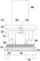
Fig. 1 is a schematic structural diagram of an embodiment of a correction device according to the present invention;
fig. 2 is a schematic structural view of a correcting tool for a battery cover plate connecting piece according to an embodiment of the present invention;
fig. 3 is a schematic structural view of the battery cover plate connecting member according to an embodiment of the present invention;
fig. 4 is a schematic structural view of an upper mold mounted on an embodiment of a straightening tool for a battery cover plate connecting piece according to the present invention;
fig. 5 is a schematic structural view of a top mold of an embodiment of a battery cover plate connector according to the present invention;
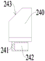
fig. 6 is a schematic structural view of the correction tool of the battery cover plate connecting piece of the present invention installed on a correction block in an embodiment;
fig. 7 is a schematic structural diagram of a correction tool for a battery cover plate connecting piece according to the present invention installed in an embodiment of a correction block.
Description of the element reference numerals
100. A base; 101. locking the bolt; 102. positioning pins;
200. a lower die; 201. a chute; 210. a connecting plate; 220. a connecting seat; 230. a drive block; 231. a drive face; 240. a correction block; 241. a slider; 242. a notch; 243. a guide surface; 244. a support block; 250. connecting blocks; 260. a thrust spring; 270. a return spring; 280. an upper die; 281. extruding the block; 282. a base plate;
300. mounting a plate;
400. a lifting mechanism.
Detailed Description
The following description of the embodiments of the present invention is provided for illustrative purposes, and other advantages and effects of the present invention will be readily apparent to those skilled in the art from the disclosure herein. The present invention can also be implemented or applied through other different specific embodiments, and various details in the present specification can be modified or changed based on different viewpoints and applications without departing from the spirit of the present invention.
Referring to fig. 1, the present invention provides a correction device for correcting a connection member of a battery cover plate, so that the connection member of the battery cover plate is in a compliant state, and the utilization rate of the connection member of the cover plate is improved. Wherein, correction equipment can include mounting panel 300, set up the board on mounting panel 300 and set up the correction frock that is used for battery cover plate connecting piece to correct on the board. Specifically, the press machine equipped with the lifting mechanism 400 may be used for the machine table, and for example, the machine table may be used for a press machine. Therefore, when the correction tool is connected to the punching machine, the punching machine drives the correction tool to correct the connecting piece of the battery cover plate.
Referring to fig. 1 to 7, in an embodiment, a correction tool for correcting a battery cover plate connector may include a lower die 200, an upper die 280, and a correction mechanism disposed between the lower die 200 and the upper die 280. Therefore, the connector may be allowed to be positioned between the upper die 280 and the lower die 200 to improve the form of the connector itself by the press-fit between the upper die 280 and the lower die 200 and the modification of the connector by the modification mechanism.
Specifically, the straightening tool may further include a connection plate 210 for connecting with the lifting mechanism 400 of the laminating machine. Thus, the connection plate 210 may be allowed to be directly driven to move by the elevating mechanism 400. The connection plate 210 is located at one side of the lower mold 200, and the connection seat 220 is further connected to the connection plate 210. Wherein, one side of the connecting seat 220 close to the lower die 200 is provided with a connecting block 250, and the connecting block 250 is movably connected with the connecting seat 220. Specifically, a thrust spring 260 is disposed between the connection holder 220 and the connection block 250, and the compression direction of the thrust spring 260 is the moving direction of the connection block 250. Wherein the upper mold 280 is coupled to the connecting block 250, so that the connecting plate 210 can continue to move to compress the thrust spring 260 after the upper mold 280 is brought into contact with the lower mold 200 while the connecting plate 210 is in the process of moving.
Referring to fig. 1-7, in one embodiment, the upper mold 280 may include a bottom plate 282 and pressing blocks 281 disposed on both sides of the bottom plate 282. The upper die 280 may be removably coupled to the connector block 250 to facilitate replacement of the upper die 280 with a different type of connector. Specifically, the upper mold 280 and the connecting block 250 may be connected by bolts, but not limited thereto, and may be determined according to actual requirements. Specifically, the bottom plate 282 is located on the end surface of the connection block 250, and the pressing block 281 is fixedly connected to the side wall of the connection block 250. Therefore, the bottom plate 282 and the pressing blocks 281 can be always tightly connected with the connecting member.
Referring to fig. 1-7, in one embodiment, the correction mechanism is located between the connecting seats 220 of the lower mold 200. The correcting mechanism may include a driving block 230 and a correcting block 240, and the correcting block 240 and the driving block 230 are respectively provided in two sets, and the correcting block 240 and the driving block 230 are correspondingly provided.
Specifically, two sets of sliding grooves 201 may be allowed to be formed on the lower mold 200, and a set of correction blocks 240 is slidably connected in each set of sliding grooves 201. Wherein, a supporting block 244 is fixedly connected to the side of the correcting block 240, and a slider 241 is fixedly connected to the bottom of the correcting block 240. The slider 241 is located in the slide groove 201, and the supporting block 244 is located on the surface of the lower die 200. Therefore, the correcting block 240 is allowed to slide along the slide groove 201 by the slider 241 and the supporting block 244. It should be noted that the slider 241 may be allowed to have a notch 242, and the return spring 270 is connected in the notch 242, and the other end of the return spring 270 is connected to the end surface of the sliding chute 201. Therefore, when the correction block 240 moves along the slide groove 201, it is allowed to timely return the correction block 240 by the return spring 270. Meanwhile, a driving surface 231 is further opened at an end of the correcting block 240, and the driving surface 231 is used for connecting with the driving block 230.
Referring to fig. 1-7, in one embodiment, the driving block 230 is fixedly connected to the connecting socket 220, so that the driving block 230 can allow the connecting socket 220 to move synchronously. The driving block 230 further has a driving surface 231, and the driving surface 231 contacts the guide surface 243. Specifically, the driving surface 231 and the guide surface 243 are inclined surfaces, and the angle of the inclined surfaces is 45 degrees.
It should be noted that the return spring 270 and the driving mass 230 are respectively located at both sides of the correcting mass 240. Therefore, when the driving block 230 is in motion, the driving surface 231 may allow the correction block 240 driven by the guide surface 243 to slide along the slide groove 201. Further, when the correction block 240 is in the process of sliding, the correction block 240 acts on the connection member, so that the connection member is located between the pressing block 281 and the correction block 240, so that the correction process of the connection member is realized through the pressing action between the correction block 240 and the pressing block 281.
Referring to fig. 1-7, in one embodiment, the mounting plate 300 further allows the base 100 to be connected thereto, and the lower mold 200 is fixedly connected to the base 100. A plurality of positioning pins 102 may be provided on the base 100, so that the positioning process of the lower mold 200 is realized by the positioning pins 102. And, the base 100 and the lower mold 200 may be detachably connected by a locking bolt 101 to facilitate replacement of the lower mold 200.
To sum up, the utility model discloses a correction frock and correction equipment of battery apron connecting piece, driving face 231 and guide face 243 are the inclined plane setting. During the movement of the driving block 230, the correcting block 240 driven by the guiding surface 243 by the driving surface 231 slides along the chute 201, and the connecting piece is positioned between the pressing block 281 and the correcting block 240, so that the correcting process of the connecting piece is realized through the pressing action between the correcting block 240 and the pressing block 281.
Therefore, the correction treatment of the connecting piece of the battery cover plate can be effectively improved, so that the connecting piece of the battery cover plate is in a compliance state, and the utilization rate of the connecting piece of the cover plate which is deformed is improved.
Therefore, the utility model discloses thereby some practical problems among the prior art have effectively been overcome and very high value of utilization and use meaning have.
The above embodiments are merely illustrative of the principles and effects of the present invention, and are not to be construed as limiting the invention. Modifications and variations can be made to the above-described embodiments by those skilled in the art without departing from the spirit and scope of the present invention. Accordingly, it is intended that all equivalent modifications or changes which may be made by those skilled in the art without departing from the spirit and technical spirit of the present invention shall be covered by the claims of the present invention.
Claims (9)
1. The utility model provides a battery cover plate connecting piece's correction frock which characterized in that includes:
a lower die (200) provided with a chute (201);
a correction block (240) which is positioned in the chute (201), is connected with the lower die (200) in a sliding way, and a guide surface (243) is arranged at the end part of the correction block (240);
the connecting plate (210) is positioned on one side of the lower die (200), and a connecting seat (220) is fixedly connected to the connecting plate (210);
the connecting block (250) is positioned on the connecting seat (220), and the connecting block (250) is movably connected with the connecting seat (220);
an upper die (280) which is positioned at the end part of the connecting block (250), and the upper die (280) is detachably connected with the connecting block (250); and
the driving block (230) is fixedly connected to the connecting seat (220), and a driving surface (231) is formed at the end part of the driving block (230);
wherein the driving surface (231) is jointed with the guide surface (243), and the driving block (230) can drive the correcting block (240) to slide in the sliding chute (201).
2. The tool for correcting the battery cover plate connecting piece according to claim 1, wherein two groups of sliding grooves (201) are arranged, and two groups of driving blocks (230) are arranged; wherein the driving block (230) and the correcting block (240) in the sliding chute (201) are correspondingly arranged.
3. The tool for correcting the battery cover plate connecting piece according to claim 1, further comprising a return spring (270) disposed in the sliding groove (201), wherein one end of the return spring (270) is connected to the correcting block (240), and the other end of the return spring (270) is connected to an end surface of the sliding groove (201).
4. The tool for correcting the battery cover plate connecting piece according to claim 3, wherein the return spring (270) and the driving block (230) are respectively positioned on two sides of the correcting block (240).
5. The tool for correcting the battery cover plate connecting piece according to claim 1, further comprising a thrust spring (260) located between the connecting block (250) and the connecting seat (220), wherein a compression direction of the thrust spring (260) is located in an active direction of the connecting block (250).
6. The tool for straightening a battery cover plate connecting piece according to claim 3, wherein the upper die (280) comprises:
the bottom plate (282) is fixedly connected to the end face of the connecting block (250); and
the two groups of extrusion blocks (281) are arranged, and the extrusion blocks (281) are fixedly connected to the side wall of the connecting block (250);
wherein, two groups of the extrusion blocks (281) are fixedly connected with the bottom plate (282).
7. The tool for correcting the battery cover plate connecting piece according to claim 1, further comprising a base (100) fixedly connected with the lower die (200).
8. The tool for correcting the battery cover plate connecting piece according to claim 7, further comprising a locking bolt (101) and a positioning pin (102), wherein the locking bolt (101) is screwed between the base (100) and the lower die (200), and the positioning pin (102) is located between the lower die (200) and the base (100).
9. An orthotic device, comprising an orthotic tooling for a battery cover plate connection according to any one of claims 1 to 8.
Priority Applications (1)
| Application Number | Priority Date | Filing Date | Title |
|---|---|---|---|
| CN202222884670.7U CN218692728U (en) | 2022-10-31 | 2022-10-31 | Correction tool and correction equipment for battery cover plate connecting piece |
Applications Claiming Priority (1)
| Application Number | Priority Date | Filing Date | Title |
|---|---|---|---|
| CN202222884670.7U CN218692728U (en) | 2022-10-31 | 2022-10-31 | Correction tool and correction equipment for battery cover plate connecting piece |
Publications (1)
| Publication Number | Publication Date |
|---|---|
| CN218692728U true CN218692728U (en) | 2023-03-24 |
Family
ID=85598032
Family Applications (1)
| Application Number | Title | Priority Date | Filing Date |
|---|---|---|---|
| CN202222884670.7U Active CN218692728U (en) | 2022-10-31 | 2022-10-31 | Correction tool and correction equipment for battery cover plate connecting piece |
Country Status (1)
| Country | Link |
|---|---|
| CN (1) | CN218692728U (en) |
-
2022
- 2022-10-31 CN CN202222884670.7U patent/CN218692728U/en active Active
Similar Documents
| Publication | Publication Date | Title |
|---|---|---|
| CN205147072U (en) | Z type and crooked compound mould of double -H groove weld type of T type stamping workpiece | |
| CN201267847Y (en) | Fine adjustment positioning apparatus of precision forming mold | |
| CN219378557U (en) | Wedge type linkage based on bending die | |
| CN216120649U (en) | Battery tab bending module and battery tab shaping and welding all-in-one machine | |
| CN215355681U (en) | Stamping die capable of synchronously punching multiple surfaces | |
| CN113305197B (en) | Universal mechanical curved surface sheet metal part forming device and forming method thereof | |
| CN211803421U (en) | Negative angle bending die | |
| CN206263034U (en) | A kind of lug bending shaping mechanism | |
| CN216705685U (en) | Resonance rod opposite-punching type short-stroke stretching die | |
| CN216175882U (en) | Novel swing block type bending forming correction die structure | |
| CN212733832U (en) | Swing block bending structure of mould | |
| CN221312105U (en) | Four-corner punching die | |
| CN110252886B (en) | Stamping process of hardware | |
| CN218798410U (en) | Double-bending forming die | |
| CN208840336U (en) | A kind of segmented sheet metal component molding machine | |
| CN210208274U (en) | Mould for pipe stamping | |
| CN221747654U (en) | Terminal processing and forming die | |
| CN223011578U (en) | Upper and lower die structure of hydraulic numerical control bending machine | |
| CN221817040U (en) | Shaping jig for communication base station die-casting raw materials | |
| CN221199191U (en) | Stable and accurate tensile test piece jig | |
| CN218693169U (en) | Bending die for metal piece and bending equipment applied by bending die | |
| CN214556717U (en) | Acute-angle bending die structure | |
| CN221289132U (en) | Front Liang Wanguan stamping and flattening die for vehicle | |
| CN211839817U (en) | A stamping die for electrical welding tab | |
| CN219274251U (en) | Elastic sheet bending tool |
Legal Events
| Date | Code | Title | Description |
|---|---|---|---|
| GR01 | Patent grant | ||
| GR01 | Patent grant |