CN218690197U - High-efficient ore processing machine of smashing ore - Google Patents
High-efficient ore processing machine of smashing ore Download PDFInfo
- Publication number
- CN218690197U CN218690197U CN202222980736.2U CN202222980736U CN218690197U CN 218690197 U CN218690197 U CN 218690197U CN 202222980736 U CN202222980736 U CN 202222980736U CN 218690197 U CN218690197 U CN 218690197U
- Authority
- CN
- China
- Prior art keywords
- fixedly connected
- wall
- crushing
- ore
- limit
- Prior art date
- Legal status (The legal status is an assumption and is not a legal conclusion. Google has not performed a legal analysis and makes no representation as to the accuracy of the status listed.)
- Active
Links
Images


Landscapes
- Crushing And Grinding (AREA)
Abstract
本实用新型涉及矿石加工机技术领域,具体为一种高效粉碎矿石的矿石加工机,包括基座,所述基座的侧壁固定连接有一对支撑板,所述支撑板的顶端固定连接有横梁,所述横梁的右侧固定连接有机箱,所述横梁左右两侧设有控制箱,破碎机构,所述破碎机构包括电机,所述电机固定连接在机箱的内部,更换机构,所述更换机构包括第一锥形齿轮,所述第一锥形齿轮设在控制箱的内部右侧。本实用新型实现对矿石的破碎,避免部分设备的破碎面积受限于颚板的形状,提升了设备的空间利用率,同时通过更换机构实现对出料板的更换,避免部分设备的出料口受到较大的应力容易产生较大的磨损,提升压合板的使用寿命。
The utility model relates to the technical field of ore processing machines, in particular to an ore processing machine for efficiently crushing ore, comprising a base, a pair of support plates are fixedly connected to the side walls of the base, and a beam is fixedly connected to the top of the support plate , the right side of the beam is fixedly connected with an organic box, the left and right sides of the beam are provided with a control box, a crushing mechanism, the crushing mechanism includes a motor, and the motor is fixedly connected to the inside of the chassis, and the replacement mechanism, the replacement mechanism A first bevel gear is included, and the first bevel gear is provided on the inner right side of the control box. The utility model realizes the crushing of ore, avoids the crushing area of some equipment being limited by the shape of the jaw plate, improves the space utilization rate of the equipment, and realizes the replacement of the discharge plate through the replacement mechanism, avoiding the discharge port of some equipment It is easy to produce greater wear and tear under greater stress, which improves the service life of the pressing plate.
Description
技术领域technical field
本实用新型涉及矿石加工机技术领域,具体为一种高效粉碎矿石的矿石加工机。The utility model relates to the technical field of ore processing machines, in particular to an ore processing machine for efficiently crushing ore.
背景技术Background technique
矿石加工机主要包括用于矿石运输、粉碎和筛选等加工的机器,其中主要用于矿石加工的机械设备为粉碎机,矿石粉碎机主要是通过电机带动转子在破碎腔内高速旋转,使得物料自上部给料口给入机内,并受到高速运动的锤子的打击、冲击、剪切、研磨等作用而粉碎,矿石粉碎机依据破碎原理的不同可以分为颚式破碎机、辊式破碎机和圆锥破碎机等不同类型,从以满足不同类型矿石的破碎研磨。Ore processing machines mainly include machines for ore transportation, crushing and screening, among which the mechanical equipment mainly used for ore processing is a crusher. The ore crusher mainly uses a motor to drive the rotor to rotate at a high speed in the crushing chamber, so that the material is automatically crushed. The upper part of the feeding port is fed into the machine, and is crushed by the impact, impact, shearing, grinding, etc. of the high-speed hammer. According to the different crushing principles, the ore crusher can be divided into jaw crusher, roller crusher and Different types of cone crushers are used to meet the crushing and grinding of different types of ores.
现有矿石破碎机主要通过调节研磨辊之间的距离来适配不同直径的矿石,现有技术多类似一种高效的矿石加工用粉碎装置,专利号为CN215140286U的构造包括支撑底座,所述支撑底座的底部左右两侧均固定安装有承重柱,所述支撑底座的顶部固定安装有粉碎箱,所述粉碎箱的顶部固定安装有进料管,所述进料管的顶部固定安装有进料漏斗,该高效的矿石加工用粉碎装置,在遇到不同直径的矿石时,在粉碎过程中可通过挤压弹簧收缩,来适配不同直径的矿石,并对其进行粉碎,大大提高了粉碎效率,但是该装置依旧存在可以优化的地方。The existing ore crusher mainly adjusts the distance between the grinding rollers to adapt to ores of different diameters. The prior art is mostly similar to a high-efficiency ore processing crushing device. The structure of the patent No. CN215140286U includes a support base, and the support The left and right sides of the bottom of the base are fixed with load-bearing columns, the top of the support base is fixed with a crushing box, the top of the crushing box is fixed with a feeding pipe, and the top of the feeding pipe is fixed with a feeding pipe. Funnel, this high-efficiency crushing device for ore processing, when encountering ore with different diameters, it can be adapted to and crushed by squeezing the spring during the crushing process, which greatly improves the crushing efficiency , but the device still has room for optimization.
1、现有颚式破碎机主要采用固定颚板和可动颚板的配合对矿石进行粉碎,但是部分设备的破碎面积受限于颚板的规格,从而导致部分设备的空间利用率较低。1. Existing jaw crushers mainly use the combination of fixed jaw plate and movable jaw plate to crush ore, but the crushing area of some equipment is limited by the specifications of the jaw plate, resulting in low space utilization of some equipment.
2、同时部分设备的出料口受到较大的应力容易产生较大的磨损,从而导致部分设备需要经常更换压合板而浪费资源,降低装置的破碎效率和实用性。2. At the same time, the discharge port of some equipment is subject to greater stress and is prone to greater wear, which leads to the need for frequent replacement of pressing plates in some equipment and wastes resources, reducing the crushing efficiency and practicability of the device.
实用新型内容Utility model content
本实用新型的目的在于提供一种高效粉碎矿石的矿石加工机,以解决上述背景技术中提出的现有颚式破碎机主要采用固定颚板和可动颚板的配合对矿石进行粉碎,但是部分设备的破碎面积受限于颚板的规格,从而导致部分设备的空间利用率较低,同时部分设备的出料口受到较大的应力容易产生较大的磨损,从而导致部分设备需要经常更换压合板的问题。The purpose of this utility model is to provide an ore processing machine for efficiently crushing ore, so as to solve the problem that the existing jaw crusher proposed in the above background technology mainly uses the cooperation of fixed jaw plate and movable jaw plate to crush ore, but some The crushing area of the equipment is limited by the specifications of the jaw plate, which leads to low space utilization of some equipment. At the same time, the discharge port of some equipment is subject to greater stress and is prone to greater wear, resulting in the need for frequent replacement of some equipment. Plywood problem.
为实现上述目的,本实用新型提供如下技术方案:一种高效粉碎矿石的矿石加工机,包括:In order to achieve the above purpose, the utility model provides the following technical solutions: an ore processing machine for efficiently crushing ore, comprising:
基座,所述基座的侧壁固定连接有一对支撑板,所述支撑板的顶端固定连接有横梁,所述横梁的右侧固定连接有机箱,所述横梁左右两侧设有控制箱;The base, the side wall of the base is fixedly connected with a pair of support plates, the top of the support plate is fixedly connected with a beam, the right side of the beam is fixedly connected with an organic box, and the left and right sides of the beam are provided with control boxes;
破碎机构,所述破碎机构包括电机,所述电机固定连接在机箱的内部,所述电机的左侧固定连接有传动轴,所述传动轴的左端穿过横梁并贯穿有升降箱,所述升降箱插设在横梁的中部,所述升降箱的内壁活动连接有齿条带组,所述齿条带组的内壁啮合连接有半齿轮,所述半齿轮的内壁固定连接在传动轴的外壁,所述支撑板的表面固定连接有控制台,所述升降箱的底端固定连接有压盖,所述压盖的底端固定连接有限位柱,所述限位柱的底端插设在基座的顶端中部,所述限位柱的外壁套设有破碎筒,所述破碎筒的外壁固定连接在支撑板的内壁中部,所述破碎筒的顶端固定连接有备料座,所述备料座的外壁固定连接在支撑板的内壁上方;Crushing mechanism, the crushing mechanism includes a motor, the motor is fixedly connected to the inside of the cabinet, the left side of the motor is fixedly connected with a transmission shaft, the left end of the transmission shaft passes through the beam and penetrates the lifting box, the lifting The box is inserted in the middle of the beam, and the inner wall of the lifting box is movably connected with a rack belt group, and the inner wall of the rack belt group is meshed with a half gear, and the inner wall of the half gear is fixedly connected with the outer wall of the transmission shaft. The surface of the support plate is fixedly connected with a console, and the bottom end of the lifting box is fixedly connected with a gland, and the bottom end of the gland is fixedly connected with a limit column, and the bottom end of the limit column is inserted into the base In the middle part of the top of the seat, the outer wall of the limiting column is covered with a crushing cylinder, the outer wall of the crushing cylinder is fixedly connected to the middle part of the inner wall of the support plate, and the top of the crushing cylinder is fixedly connected with a material preparation seat, and the material preparation seat The outer wall is fixedly connected above the inner wall of the support plate;
更换机构,所述更换机构包括第一锥形齿轮,所述第一锥形齿轮设在控制箱的内部右侧。A replacement mechanism, the replacement mechanism includes a first bevel gear, and the first bevel gear is arranged on the inner right side of the control box.
优选的,所述横梁内壁左侧开设有与传动轴对应的限位槽,所述横梁内壁右侧开设有与传动轴对应的限位孔,所述升降箱的侧壁开设有与传动轴对应的限位滑缝。Preferably, the left side of the inner wall of the crossbeam is provided with a limit groove corresponding to the transmission shaft, the right side of the inner wall of the crossbeam is provided with a limit hole corresponding to the transmission shaft, and the side wall of the lifting box is provided with a limit hole corresponding to the transmission shaft. limit slip.
优选的,所述基座的顶部开设有与限位柱对应的限位滑槽。Preferably, the top of the base is provided with a limit chute corresponding to the limit column.
优选的,所述破碎筒的内壁呈倒立圆台状。Preferably, the inner wall of the crushing cylinder is in the shape of an inverted truncated cone.
优选的,所述第一锥形齿轮的左侧固定连接有转动轴,所述转动轴的右端穿过控制箱并固定连接有握把,所述第一锥形齿轮的底部右侧啮合连接有第二锥形齿轮,所述第二锥形齿轮的内壁活动连接有螺杆,所述第二锥形齿轮的内壁开设有与螺杆对应的螺纹孔,所述螺杆的底端穿过控制箱并固定连接有限位块。Preferably, the left side of the first bevel gear is fixedly connected with a rotating shaft, the right end of the rotating shaft passes through the control box and is fixedly connected with a handle, and the bottom right side of the first bevel gear is engaged with a The second bevel gear, the inner wall of the second bevel gear is movably connected with a screw rod, the inner wall of the second bevel gear is provided with a threaded hole corresponding to the screw rod, and the bottom end of the screw rod passes through the control box and is fixed Connect the limited block.
优选的,所述基座的顶部两侧固定连接有支撑杆,所述支撑杆的顶端活动连接有出料板,所述出料板的外壁活动连接在支撑板的内壁,所述支撑板的内壁开设有与出料板对应的限位滑道。Preferably, both sides of the top of the base are fixedly connected with support rods, the top of the support rods is movably connected with a discharge plate, the outer wall of the discharge plate is movably connected with the inner wall of the support plate, and the support plate The inner wall is provided with a limit slideway corresponding to the discharge plate.
与现有技术相比,本实用新型的有益效果是:Compared with the prior art, the beneficial effects of the utility model are:
1、该高效粉碎矿石的矿石加工机设置有破碎机构,通过控制台启动电机带动传动轴和半齿轮同步转动,啮合带动齿条带组反复运动,齿条带组带动升降箱、压盖同步运动,压盖带动限位柱在限位滑槽的内部同步滑动,物料通过备料座进入破碎筒的内部,使得压盖和限位柱带动矿石与破碎筒的内壁挤压摩擦,通过上述设计,实现对矿石的破碎,避免部分设备的破碎面积受限于颚板的形状,从而避免部分设备的空间利用率较低,使得破碎效率得到提高,提高了装置的高效性和实用性。1. The ore processing machine for efficiently crushing ore is equipped with a crushing mechanism. The drive shaft and the half gear are driven to rotate synchronously through the console startup motor, and the meshing drives the rack belt group to move repeatedly, and the rack belt group drives the lifting box and the gland to move synchronously , the gland drives the limit column to slide synchronously inside the limit chute, and the material enters the inside of the crushing cylinder through the material preparation seat, so that the gland and the limit column drive the ore to squeeze and rub against the inner wall of the crushing cylinder. Through the above design, the For the crushing of ore, it avoids the crushing area of some equipment being limited by the shape of the jaw plate, thereby avoiding the low space utilization rate of some equipment, improving the crushing efficiency, and improving the efficiency and practicability of the device.
2、该高效粉碎矿石的矿石加工机设置有更换机构,通过在支撑板的内壁下方设有与出料板限位滑道,通过转动握把,握把带动转动轴、锥形齿轮同步转动,螺杆受到螺纹孔的限制,使得螺杆带动限位块上下滑动并将出料板的限位固定在破碎筒的底部,通过上述设计,实现对出料板的更换,避免部分设备的出料口受到较大的应力容易产生较大的磨损,从而避免部分压合板的使用寿命降低,使得破碎效率得到提高,提高了装置的便捷性和实用性。2. The ore processing machine for efficiently crushing ore is equipped with a replacement mechanism. By setting a limit slideway with the discharge plate under the inner wall of the support plate, by turning the handle, the handle drives the rotating shaft and the bevel gear to rotate synchronously. The screw is limited by the threaded hole, so that the screw drives the limit block to slide up and down and fixes the limit of the discharge plate on the bottom of the crushing cylinder. Through the above design, the replacement of the discharge plate is realized, and the discharge port of some equipment is avoided. Greater stress is likely to cause greater wear, thereby avoiding the reduction of the service life of some pressing plates, improving the crushing efficiency, and improving the convenience and practicability of the device.
附图说明Description of drawings
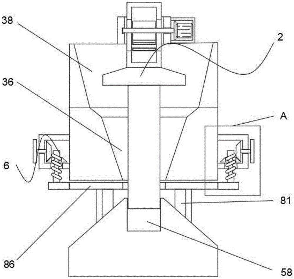
图1为本实用新型的结构正视示意图;Fig. 1 is the structural front view schematic diagram of the present utility model;
图2为本实用新型的结构正视剖面示意图;Fig. 2 is the schematic cross-sectional view of the structure of the utility model;
图3为本实用新型支撑柱和破碎机构的局部结构正视剖面示意图;Fig. 3 is a front view sectional schematic diagram of the local structure of the support column and the crushing mechanism of the utility model;
图4为本实用新型图2中A处结构放大示意图;Fig. 4 is the enlarged schematic view of the structure at A in Fig. 2 of the present utility model;
图5为本实用新型的结构侧视剖面示意图。Fig. 5 is a schematic side view sectional view of the structure of the utility model.
图中:11、基座;12、支撑板;13、横梁;15、机箱;16、控制箱;2、破碎机构;21、电机;22、传动轴;23、升降箱;25、齿条带组;26、半齿轮;28、控制台;31、压盖;32、限位柱;36、破碎筒;38、备料座;51、限位槽;52、限位孔;56、限位滑缝;58、限位滑槽;6、更换机构;61、第一锥形齿轮;62、转动轴;63、握把;65、第二锥形齿轮;66、螺杆;67、螺纹孔;68、限位块;81、支撑杆;86、出料板;88、限位滑道。In the figure: 11, base; 12, support plate; 13, beam; 15, chassis; 16, control box; 2, crushing mechanism; 21, motor; 22, drive shaft; 23, lifting box; 25, rack belt Group; 26, half gear; 28, console; 31, gland; 32, limit post; 36, crushing cylinder; 38, spare seat; 51, limit groove; 52, limit hole; 56, limit slide Seam; 58, limit chute; 6, replacement mechanism; 61, first bevel gear; 62, rotating shaft; 63, handle; 65, second bevel gear; 66, screw rod; 67, threaded hole; 68 , limit block; 81, support rod; 86, discharge plate; 88, limit slideway.
具体实施方式Detailed ways
下面将结合本实用新型实施例中的附图,对本实用新型实施例中的技术方案进行清楚、完整地描述,显然,所描述的实施例仅仅是本实用新型一部分实施例,而不是全部的实施例。基于本实用新型中的实施例,本领域普通技术人员在没有做出创造性劳动前提下所获得的所有其他实施例,都属于本实用新型保护的范围。The technical solutions in the embodiments of the present invention will be clearly and completely described below in conjunction with the accompanying drawings in the embodiments of the present invention. Obviously, the described embodiments are only part of the embodiments of the present invention, not all of them. example. Based on the embodiments of the present utility model, all other embodiments obtained by persons of ordinary skill in the art without making creative efforts belong to the scope of protection of the present utility model.
请参阅图1-5,本实用新型提供的一种实施例:Please refer to Fig. 1-5, a kind of embodiment provided by the utility model:
一种高效粉碎矿石的矿石加工机,包括:An ore processing machine for efficiently crushing ore, including:
基座11,基座11的侧壁固定连接有一对支撑板12,支撑板12的顶端固定连接有横梁13,横梁13的右侧固定连接有机箱15,横梁13左右两侧设有控制箱16;A
破碎机构2,破碎机构2包括电机21,电机21固定连接在机箱15的内部,电机21的左侧固定连接有传动轴22,传动轴22的左端穿过横梁13并贯穿有升降箱23,横梁13内壁左侧开设有与传动轴22对应的限位槽51,横梁13内壁右侧开设有与传动轴22对应的限位孔52,升降箱23的侧壁开设有与传动轴22对应的限位滑缝56,通过该设计,实现了传动轴22的限位转动,同时实现了升降箱23的限位滑动,升降箱23插设在横梁13的中部,升降箱23的内壁活动连接有齿条带组25,齿条带组25的内壁啮合连接有半齿轮26,半齿轮26的内壁固定连接在传动轴22的外壁,支撑板12的表面固定连接有控制台28,升降箱23的底端固定连接有压盖31,压盖31的底端固定连接有限位柱32,限位柱32的底端插设在基座11的顶端中部,基座11的顶部开设有与限位柱32对应的限位滑槽58,通过该设计,实现了提升限位柱32升降过程中的稳定性,限位柱32的外壁套设有破碎筒36,破碎筒36的内壁呈倒立圆台状,通过该设计,实现了物料自动滑入和滑出破碎筒36,同时降低了设备破碎过程中的负荷,破碎筒36的外壁固定连接在支撑板12的内壁中部,破碎筒36的顶端固定连接有备料座38,备料座38的外壁固定连接在支撑板12的内壁上方;The
更换机构6,更换机构6包括第一锥形齿轮61,第一锥形齿轮61设在控制箱16的内部右侧,第一锥形齿轮61的左侧固定连接有转动轴62,转动轴62的右端穿过控制箱16并固定连接有握把63,第一锥形齿轮61的底部右侧啮合连接有第二锥形齿轮65,第二锥形齿轮65的内壁活动连接有螺杆66,第二锥形齿轮65的内壁开设有与螺杆66对应的螺纹孔67,螺杆66的底端穿过控制箱16并固定连接有限位块68,通过该设计,实现了限位块68升降,并实现对出料板86限位固定,基座11的顶部两侧固定连接有支撑杆81,支撑杆81的顶端活动连接有出料板86,出料板86的外壁活动连接在支撑板12的内壁,支撑板12的内壁开设有与出料板86对应的限位滑道88,通过该设计,实现了对出料板86的支撑。
工作原理:当需要对矿石进行破碎时,首先通过控制台28启动电机21,电机21带动传动轴22转动,传动轴22带动半齿轮26同步转动,啮合带动齿条带组25反复运动,齿条带组25带动升降箱23同步运动,升降箱23带动压盖31同步运动,压盖31带动限位柱32在限位滑槽58的内部同步滑动,然后物料通过备料座38进入破碎筒36的内部,使得压盖31和限位柱32带动矿石与破碎筒36的内壁挤压摩擦,实现对矿石的破碎操作。Working principle: When the ore needs to be crushed, first start the
当需要对出料板86进行更换时,首先将出料板86插设在支撑板12的限位滑道88内部,然后通过转动握把63,握把63带动转动轴62转动,转动轴62带动第一锥形齿轮61同步转动,第一锥形齿轮61啮合带动第二锥形齿轮65转动,螺杆66受到螺纹孔67的限制,使得螺杆66带动限位块68上下滑动,使得出料板86的限位固定在破碎筒36的底部,实现对出料板86的更换操作,操作到此结束。When it is necessary to replace the
对于本领域技术人员而言,显然本实用新型不限于上述示范性实施例的细节,而且在不背离本实用新型的精神或基本特征的情况下,能够以其他的具体形式实现本实用新型。因此,无论从哪一点来看,均应将实施例看作是示范性的,而且是非限制性的,本实用新型的范围由所附权利要求而不是上述说明限定,因此旨在将落在权利要求的等同要件的含义和范围内的所有变化囊括在本实用新型内。不应将权利要求中的任何附图标记视为限制所涉及的权利要求。It is obvious to those skilled in the art that the present invention is not limited to the details of the above exemplary embodiments, and that the present invention can be implemented in other specific forms without departing from the spirit or essential features of the present invention. Therefore, no matter from all points of view, the embodiments should be regarded as exemplary and non-restrictive, and the scope of the present invention is defined by the appended claims rather than the above description, so it is intended to fall within the scope of the claims All changes within the meaning and range of equivalents of the required elements are included in the present invention. Any reference sign in a claim should not be construed as limiting the claim concerned.
Claims (6)
Priority Applications (1)
| Application Number | Priority Date | Filing Date | Title |
|---|---|---|---|
| CN202222980736.2U CN218690197U (en) | 2022-11-09 | 2022-11-09 | High-efficient ore processing machine of smashing ore |
Applications Claiming Priority (1)
| Application Number | Priority Date | Filing Date | Title |
|---|---|---|---|
| CN202222980736.2U CN218690197U (en) | 2022-11-09 | 2022-11-09 | High-efficient ore processing machine of smashing ore |
Publications (1)
| Publication Number | Publication Date |
|---|---|
| CN218690197U true CN218690197U (en) | 2023-03-24 |
Family
ID=85612388
Family Applications (1)
| Application Number | Title | Priority Date | Filing Date |
|---|---|---|---|
| CN202222980736.2U Active CN218690197U (en) | 2022-11-09 | 2022-11-09 | High-efficient ore processing machine of smashing ore |
Country Status (1)
| Country | Link |
|---|---|
| CN (1) | CN218690197U (en) |
-
2022
- 2022-11-09 CN CN202222980736.2U patent/CN218690197U/en active Active
Similar Documents
| Publication | Publication Date | Title |
|---|---|---|
| CN205587085U (en) | Fodder powder grumeleuse is broken, deironing device | |
| CN203264809U (en) | Extruding type garbage crusher | |
| CN217830206U (en) | A feed mechanism for hammer mill | |
| CN103316734A (en) | Crusher tooth roller | |
| CN204933568U (en) | Novel ring hammer mill | |
| CN202021063U (en) | Toothed roll crusher | |
| CN216172558U (en) | Quick breaker of waste material | |
| CN215429280U (en) | Abandonment tectorial membrane sand vibrations formula rubbing crusher | |
| CN214293973U (en) | Plastic crusher | |
| CN213528855U (en) | Plastic processing rubbing crusher | |
| CN211412289U (en) | Material crushing and rolling device | |
| CN2411057Y (en) | double-acting jaws high energy crushing mechanism | |
| CN217249433U (en) | Crushing device for steel slag cement concrete production | |
| CN111760621A (en) | High efficiency ore crushing device | |
| CN213824977U (en) | Grinder for feed processing convenient to use | |
| CN214811152U (en) | Hydraulic cone crusher | |
| CN207413559U (en) | A kind of high multiple roll feed disintegrating apparatus of feed fineness | |
| CN216800059U (en) | Energy-concerving and environment-protective improved generation mine ball mill | |
| CN218308195U (en) | Raw material crushing apparatus | |
| CN213966811U (en) | Ore crushing equipment for non-ferrous metal smelting | |
| CN211964330U (en) | Fine crushing device for materials | |
| CN201969604U (en) | Vertical crusher | |
| CN215996854U (en) | Automatic feeding device for universal pulverizer | |
| CN215029263U (en) | Novel cardiovascular medicine raw materials is smashed device | |
| CN213193849U (en) | Novel crushing device for cable material production and processing |
Legal Events
| Date | Code | Title | Description |
|---|---|---|---|
| GR01 | Patent grant | ||
| GR01 | Patent grant | ||
| TR01 | Transfer of patent right |
Effective date of registration: 20260528 Address after: 415100 Hunan Province, Changde City, Dingcheng District, Zhendeqiao Town, Qiaojia Gang Village, Group 18 Patentee after: Mei Bing Country or region after: China Patentee after: Luo Yuanjie Patentee after: Ni Jine Patentee after: Chen Yang Address before: 461670 Henan Province Xuchang City Yuzhou City Changzhuang Township Changzhuang Village Patentee before: Yuzhou Jinxin Cement Co.,Ltd. Country or region before: China |
|
| TR01 | Transfer of patent right | ||
| TR01 | Transfer of patent right |
Effective date of registration: 20260611 Address after: 410007, Hunan Province, Changsha City, Yuhua District, Litu Street, Labor East Road, No. 1299, Inter-city New Garden, Building 3, Commercial 372 Patentee after: Hunan Xinmaofeng Mining Co.,Ltd. Country or region after: China Address before: 415100 Hunan Province, Changde City, Dingcheng District, Zhendeqiao Town, Qiaojia Gang Village, Group 18 Patentee before: Mei Bing Country or region before: China Patentee before: Luo Yuanjie Patentee before: Ni Jine Patentee before: Chen Yang |
|
| TR01 | Transfer of patent right |