CN218688064U - Waste gas treatment device is used in chemicals processing - Google Patents
Waste gas treatment device is used in chemicals processing Download PDFInfo
- Publication number
- CN218688064U CN218688064U CN202222809966.2U CN202222809966U CN218688064U CN 218688064 U CN218688064 U CN 218688064U CN 202222809966 U CN202222809966 U CN 202222809966U CN 218688064 U CN218688064 U CN 218688064U
- Authority
- CN
- China
- Prior art keywords
- gas treatment
- waste gas
- pipe
- treatment device
- tank
- Prior art date
- Legal status (The legal status is an assumption and is not a legal conclusion. Google has not performed a legal analysis and makes no representation as to the accuracy of the status listed.)
- Expired - Fee Related
Links
Images


Landscapes
- Treating Waste Gases (AREA)
Abstract
本实用新型公开了一种化工品加工用废气处理装置,涉及废气处理装置技术领域,包括废气处理罐、注料管、连接管和存储罐,所述废气处理罐的顶部固定安装有注料管,所述废气处理罐的侧面固定连接有连接管,所述连接管的另一端设置有存储罐,所述废气处理罐的中部固定连接有输料管。本实用新型通过喷淋室内喷淋氧化剂,对内部废气产生化学反应,进行净化处理,使得喷淋掉落的水分沿着喷淋室内壁流入到底部,然后由重力的影响,废水再次流入到排水槽的内部,并配合滤网进行过滤杂质颗粒物,再配合排料管进行排出废水,解决了废气处理装置的内部在处理废气时,容易产生废水,影响装置环保性能的问题,有利于装置增加环保功能,增加实用性。
The utility model discloses a waste gas treatment device for chemical product processing, relates to the technical field of waste gas treatment devices, and comprises a waste gas treatment tank, a material injection pipe, a connecting pipe and a storage tank, and the top of the waste gas treatment tank is fixed with a material injection pipe The side of the waste gas treatment tank is fixedly connected with a connecting pipe, the other end of the connecting pipe is provided with a storage tank, and the middle part of the waste gas treatment tank is fixedly connected with a feeding pipe. The utility model sprays the oxidant in the spray chamber to produce a chemical reaction on the internal waste gas and performs purification treatment, so that the water dropped by the spray flows into the bottom along the wall of the spray chamber, and then the waste water flows into the drain again due to the influence of gravity. The interior of the water tank is combined with a filter screen to filter impurities and particles, and then cooperates with a discharge pipe to discharge waste water, which solves the problem that waste water is easily generated inside the waste gas treatment device and affects the environmental protection performance of the device, which is conducive to increasing the environmental protection of the device function for added practicality.
Description
技术领域technical field
本实用新型涉及废气处理装置技术领域,具体涉及一种化工品加工用废气处理装置。The utility model relates to the technical field of waste gas treatment devices, in particular to a waste gas treatment device for chemical product processing.
背景技术Background technique
废气净化主要是指针对工业场所产生的工业废气诸如粉尘颗粒物、烟气烟尘、异味气体、有毒有害气体进行治理的工作。常见的废气净化有工厂烟尘废气净化、车间粉尘废气净化、有机废气净化、废气异味净化、酸碱废气净化、化工废气净化等。Exhaust gas purification mainly refers to the work of treating industrial waste gas such as dust particles, flue gas smoke, odorous gas, and toxic and harmful gases generated in industrial places. Common waste gas purification includes factory smoke and dust waste gas purification, workshop dust waste gas purification, organic waste gas purification, waste gas odor purification, acid-base waste gas purification, chemical waste gas purification, etc.
现有的技术方案中,提出了公开号:CN215539332U,该文献所公开的技术方案如下:一种化工品加工用废气处理装置,包括吸附壳体和喷淋壳体;所述喷淋壳体设置于吸附壳体一侧,吸附壳体底端通过连通管道与喷淋壳体底端连通,所述吸附壳体顶端开设有进气口,所述吸附壳体内部固定有吸附筒,吸附筒内部与吸附壳体内部连通,所述吸附筒内部两端分别设置有第一滤网和第二滤网,所述第一滤网和第二滤网之间填充有若干活性炭颗粒,所述第一滤网表面对称设置有挤压弹簧。Among the existing technical solutions, a publication number is proposed: CN215539332U. The technical solution disclosed in this document is as follows: a waste gas treatment device for chemical product processing, including an adsorption shell and a spray shell; the spray shell is set On one side of the adsorption housing, the bottom end of the adsorption housing communicates with the bottom end of the spray housing through a communication pipe, the top of the adsorption housing is provided with an air inlet, and an adsorption cylinder is fixed inside the adsorption housing. It communicates with the interior of the adsorption shell, and the two ends of the adsorption cylinder are respectively provided with a first filter screen and a second filter screen, and a number of activated carbon particles are filled between the first filter screen and the second filter screen, and the first filter screen and the second filter screen are filled with activated carbon particles. Squeezing springs are arranged symmetrically on the surface of the filter screen.
针对现有技术存在以下问题:There are following problems at prior art:
1、废气处理内部结构复杂,不利于工作人员便捷的拆卸,影响装置后期维护的问题;1. The internal structure of the exhaust gas treatment is complicated, which is not conducive to the convenient disassembly of the staff, and affects the later maintenance of the device;
2、废气处理装置的内部在处理废气时,容易产生废水,直接排出造成设备的环保性能降低的问题。2. When the waste gas is treated inside the waste gas treatment device, it is easy to generate waste water, which directly discharges the problem that the environmental protection performance of the equipment is reduced.
实用新型内容Utility model content
本实用新型提供一种化工品加工用废气处理装置,以解决上述背景技术中提出的问题。The utility model provides a waste gas treatment device for chemical product processing to solve the problems raised in the above-mentioned background technology.
为解决上述技术问题,本实用新型所采用的技术方案是:In order to solve the problems of the technologies described above, the technical solution adopted in the utility model is:
一种化工品加工用废气处理装置,包括废气处理罐、注料管、连接管和存储罐,所述废气处理罐的顶部固定安装有注料管,所述废气处理罐的侧面固定连接有连接管,所述连接管的另一端设置有存储罐,所述废气处理罐的中部固定连接有输料管,所述输料管的底部固定安装有水泵箱。A waste gas treatment device for chemical product processing, comprising a waste gas treatment tank, a material injection pipe, a connecting pipe and a storage tank, the top of the waste gas treatment tank is fixedly installed with a material injection pipe, and the side of the waste gas treatment tank is fixedly connected with a connecting pipe The other end of the connecting pipe is provided with a storage tank, the middle part of the exhaust gas treatment tank is fixedly connected with a feeding pipe, and the bottom of the feeding pipe is fixedly installed with a water pump box.
所述废气处理罐内腔的底部设置有喷淋室,所述喷淋室内壁的两侧固定安装有连接块,所述连接块的内侧活动安装有固定杆,所述固定杆的内部设置有传输管,所述传输管的顶部固定连接在输料管的一端上,所述传输管的底部且延伸至固定杆的底部固定安装有喷嘴。The bottom of the inner cavity of the exhaust gas treatment tank is provided with a spray chamber, and the two sides of the spray chamber wall are fixedly installed with connection blocks, and the inner side of the connection block is movably installed with a fixed rod, and the inside of the fixed rod is provided with The transfer pipe, the top of the transfer pipe is fixedly connected to one end of the feed pipe, and the bottom of the transfer pipe extends to the bottom of the fixed rod and is fixedly installed with a nozzle.
所述喷淋室内腔的底部开设有排水槽,所述排水槽的内部设置有安装轴,所述安装轴的外侧设置有过滤盘。The bottom of the spray chamber cavity is provided with a drainage groove, the inside of the drainage groove is provided with an installation shaft, and the outside of the installation shaft is provided with a filter disc.
本实用新型技术方案的进一步改进在于:所述废气处理罐内腔的顶部设置有安装板,所述安装板的内部设置有过滤板。The further improvement of the technical solution of the utility model lies in that: the top of the inner chamber of the exhaust gas treatment tank is provided with a mounting plate, and the inside of the mounting plate is provided with a filter plate.
本实用新型技术方案的进一步改进在于:所述安装板的底部设置有吸附棉垫,所述吸附棉垫的底部设置在喷淋室的顶部。The further improvement of the technical solution of the utility model lies in that: the bottom of the installation plate is provided with an adsorption cotton pad, and the bottom of the adsorption cotton pad is arranged on the top of the spray chamber.
本实用新型技术方案的进一步改进在于:所述连接块的两侧开设有限位孔,所述限位孔的内部螺纹连接有螺纹柱,所述螺纹柱的另一端延伸至固定杆的侧面。The further improvement of the technical solution of the utility model lies in that: the two sides of the connecting block are provided with limiting holes, the internal thread of the limiting hole is connected with a threaded column, and the other end of the threaded column extends to the side of the fixing rod.
本实用新型技术方案的进一步改进在于:所述过滤盘的底部固定安装有隔板柱,所述隔板柱的侧面固定安装有滤网。The further improvement of the technical solution of the utility model lies in that: the bottom of the filter disc is fixedly installed with a partition column, and the side of the partition column is fixedly installed with a filter screen.
本实用新型技术方案的进一步改进在于:所述排水槽内腔的底部且位于滤网的一侧开设有导流槽,所述导流槽的内部开设有排水孔。The further improvement of the technical solution of the utility model lies in that: a diversion groove is provided at the bottom of the inner cavity of the drainage groove and located on one side of the filter screen, and a drainage hole is provided inside the diversion groove.
本实用新型技术方案的进一步改进在于:所述排水孔的底部设置有排料管,所述排料管的另一端延伸至废气处理罐的外侧。The further improvement of the technical solution of the utility model is that: a discharge pipe is provided at the bottom of the drainage hole, and the other end of the discharge pipe extends to the outside of the waste gas treatment tank.
由于采用了上述技术方案,本实用新型相对现有技术来说,取得的技术进步是:Owing to adopting above-mentioned technical scheme, relative to the prior art, the technical progress of the utility model is:
1、本实用新型提供一种化工品加工用废气处理装置,通过螺纹柱进行螺纹旋转,使得螺纹柱从限位孔内部旋转脱离,固定杆脱离限位功能,方便固定杆两端便捷从连接块顶部脱离,达到便捷拆卸的功能,解决了废气处理内部结构复杂,不利于工作人员便捷的拆卸的问题,有利于装置便捷拆卸,节省人工劳动力。1. The utility model provides a waste gas treatment device for chemical products processing. The threaded column is rotated through the threaded column, so that the threaded column is rotated and detached from the inside of the limit hole, and the fixed rod is separated from the limit function, so that the two ends of the fixed rod can be easily removed from the connecting block. The top is detached to achieve the function of convenient disassembly, which solves the problem that the internal structure of the waste gas treatment is complicated and is not conducive to the convenient disassembly of the staff, which is conducive to the convenient disassembly of the device and saves labor.
2、本实用新型提供一种化工品加工用废气处理装置,通过喷淋室内喷淋氧化剂,对内部废气产生化学反应,进行净化处理,使得喷淋掉落的水分沿着喷淋室内壁流入到底部,然后由重力的影响,废水再次流入到排水槽的内部,并配合滤网进行过滤杂质颗粒物,再配合排料管进行排出废水,解决了废气处理装置的内部在处理废气时,容易产生废水,影响装置环保性能的问题,有利于装置增加环保功能,增加实用性。2. The utility model provides a waste gas treatment device for chemical product processing. The oxidant is sprayed in the spray chamber to produce a chemical reaction on the internal waste gas and perform purification treatment, so that the water dropped by the spray flows into the bottom along the wall of the spray chamber Then, under the influence of gravity, the waste water flows into the drainage tank again, and cooperates with the filter screen to filter the impurity particles, and then cooperates with the discharge pipe to discharge the waste water, which solves the problem that waste water is easily generated inside the waste gas treatment device when treating waste gas. , the problem of affecting the environmental protection performance of the device is beneficial to increase the environmental protection function of the device and increase the practicability.
附图说明Description of drawings
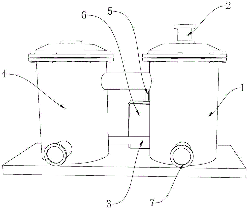
图1为本实用新型的结构示意图;Fig. 1 is the structural representation of the utility model;
图2为本实用新型的废气处理罐结构示意图;Fig. 2 is the structural representation of the exhaust gas treatment tank of the present utility model;
图3为本实用新型的固定杆结构示意图;Fig. 3 is the structural representation of the fixed rod of the present utility model;
图4为本实用新型的连接块结构示意图;Fig. 4 is the structural representation of the connection block of the present utility model;
图5为本实用新型的排水槽结构示意图。Fig. 5 is a structural schematic diagram of the drainage tank of the present invention.
图中:1、废气处理罐;11、安装板;12、过滤板;13、吸附棉垫;14、喷淋室;15、传输管;16、固定杆;17、连接块;171、限位孔;172、螺纹柱;18、喷嘴;19、排水槽;191、安装轴;192、过滤盘;193、隔板柱;194、滤网;195、导流槽;2、注料管;3、连接管;4、存储罐;5、输料管;6、水泵箱;7、排料管。In the figure: 1, exhaust gas treatment tank; 11, installation plate; 12, filter plate; 13, adsorption cotton pad; 14, spray room; 15, transmission pipe; 16, fixed rod; 17, connection block; Hole; 172, threaded column; 18, nozzle; 19, drainage groove; 191, installation shaft; 192, filter plate; 193, clapboard column; 194, filter screen; , connecting pipe; 4, storage tank; 5, feeding pipe; 6, water pump box; 7, discharge pipe.
具体实施方式Detailed ways
下面结合实施例对本实用新型做进一步详细说明:Below in conjunction with embodiment the utility model is described in further detail:
实施例1Example 1
如图1-5所示,本实用新型提供了一种化工品加工用废气处理装置,包括废气处理罐1、注料管2、连接管3和存储罐4,废气处理罐1的顶部固定安装有注料管2,废气处理罐1的侧面固定连接有连接管3,连接管3的另一端设置有存储罐4,废气处理罐1的中部固定连接有输料管5,输料管5的底部固定安装有水泵箱6,废气处理罐1内腔的底部设置有喷淋室14,喷淋室14内壁的两侧固定安装有连接块17,连接块17的内侧活动安装有固定杆16,固定杆16的内部设置有传输管15,传输管15的顶部固定连接在输料管5的一端上,传输管15的底部且延伸至固定杆16的底部固定安装有喷嘴18,废气处理罐1内腔的顶部设置有安装板11,安装板11的内部设置有过滤板12,安装板11的底部设置有吸附棉垫13,吸附棉垫13的底部设置在喷淋室14的顶部。As shown in Figures 1-5, the utility model provides a waste gas treatment device for chemical product processing, including a waste
在本实施例中,通过注料管2进行注入废气,使得废气进入到废气处理罐1的内部,利用过滤板12和吸附棉垫13相互配合,对废气进行过滤吸附处理,处理后的气体进入到喷淋室14的内部,再由水泵箱6配合输料管5对传输管15输入氧化剂,再由喷嘴18对喷淋室14内部喷淋,方便对废气进行化学反应,达到便捷处理废气的功能,有利于装置增加便捷性。In this embodiment, the exhaust gas is injected through the
实施例2Example 2
如图1-5所示,在实施例1的基础上,本实用新型提供一种技术方案:优选的,连接块17的两侧开设有限位孔171,限位孔171的内部螺纹连接有螺纹柱172,螺纹柱172的另一端延伸至固定杆16的侧面。As shown in Figures 1-5, on the basis of
在本实施例中,通过螺纹柱172进行螺纹旋转,使得螺纹柱172从限位孔171内部旋转脱离,固定杆16脱离限位功能,方便固定杆16两端便捷从连接块17顶部脱离,达到便捷拆卸的功能,有利于装置增加便捷性。In this embodiment, the threaded
实施例3Example 3
如图1-5所示,在实施例1的基础上,本实用新型提供一种技术方案:优选的,喷淋室14内腔的底部开设有排水槽19,排水槽19的内部设置有安装轴191,安装轴191的外侧设置有过滤盘192,过滤盘192的底部固定安装有隔板柱193,隔板柱193的侧面固定安装有滤网194,排水槽19内腔的底部且位于滤网194的一侧开设有导流槽195,导流槽195的内部开设有排水孔,排水孔的底部设置有排料管7,排料管7的另一端延伸至废气处理罐1的外侧。As shown in Figures 1-5, on the basis of
在本实施例中,通过喷淋室14内喷淋氧化剂,对内部废气产生化学反应,进行净化处理,使得喷淋掉落的水分沿着喷淋室14内壁流入到底部,然后由重力的影响,废水再次流入到排水槽19的内部,并配合滤网194进行过滤杂质颗粒物,再配合排料管7进行排出废水,有利于装置增加环保功能。In this embodiment, by spraying the oxidant in the
下面具体说一下该化工品加工用废气处理装置的工作原理。Let's talk about the working principle of the waste gas treatment device for chemical processing in detail.
如图1-5所示,通过注料管2进行注入废气,使得废气进入到废气处理罐1的内部,利用过滤板12和吸附棉垫13相互配合,对废气进行过滤吸附处理,处理后的气体进入到喷淋室14的内部,再由水泵箱6配合输料管5对传输管15输入氧化剂,再由喷嘴18对喷淋室14内部喷淋,方便对废气进行化学反应,达到便捷处理废气的功能,再通过喷淋室14内喷淋氧化剂,对内部废气产生化学反应,进行净化处理,使得喷淋掉落的水分沿着喷淋室14内壁流入到底部,然后由重力的影响,废水再次流入到排水槽19的内部,并配合滤网194进行过滤杂质颗粒物,再配合排料管7进行排出废水,净化的气体配合连接管3传输到存储罐4的内部,在设备维护时,通过螺纹柱172进行螺纹旋转,使得螺纹柱172从限位孔171内部旋转脱离,固定杆16脱离限位功能,方便固定杆16两端便捷从连接块17顶部脱离,达到便捷拆卸的功能。As shown in Figure 1-5, the waste gas is injected through the
上文一般性的对本实用新型做了详尽的描述,但在本实用新型基础上,可以对之做一些修改或改进,这对于技术领域的一般技术人员是显而易见的。因此,在不脱离本实用新型思想精神的修改或改进,均在本实用新型的保护范围之内。The above has generally described the utility model in detail, but on the basis of the utility model, some modifications or improvements can be made to it, which is obvious to those skilled in the art. Therefore, any modification or improvement that does not depart from the spirit of the present utility model is within the protection scope of the present utility model.
Claims (7)
Priority Applications (1)
| Application Number | Priority Date | Filing Date | Title |
|---|---|---|---|
| CN202222809966.2U CN218688064U (en) | 2022-10-24 | 2022-10-24 | Waste gas treatment device is used in chemicals processing |
Applications Claiming Priority (1)
| Application Number | Priority Date | Filing Date | Title |
|---|---|---|---|
| CN202222809966.2U CN218688064U (en) | 2022-10-24 | 2022-10-24 | Waste gas treatment device is used in chemicals processing |
Publications (1)
| Publication Number | Publication Date |
|---|---|
| CN218688064U true CN218688064U (en) | 2023-03-24 |
Family
ID=85588992
Family Applications (1)
| Application Number | Title | Priority Date | Filing Date |
|---|---|---|---|
| CN202222809966.2U Expired - Fee Related CN218688064U (en) | 2022-10-24 | 2022-10-24 | Waste gas treatment device is used in chemicals processing |
Country Status (1)
| Country | Link |
|---|---|
| CN (1) | CN218688064U (en) |
-
2022
- 2022-10-24 CN CN202222809966.2U patent/CN218688064U/en not_active Expired - Fee Related
Similar Documents
| Publication | Publication Date | Title |
|---|---|---|
| CN215782298U (en) | Environment-friendly device is used in stabilizer production and processing | |
| CN219700614U (en) | Plasma deodorization equipment | |
| CN207769492U (en) | A kind of novel VOC waste gas purification apparatuses | |
| CN214513736U (en) | A waste gas treatment device for angle steel welding | |
| CN211069597U (en) | An energy-saving organic waste gas treatment device | |
| CN212819010U (en) | Deodorization device of integrated sewage treatment equipment | |
| CN220677387U (en) | Waste gas treatment equipment | |
| CN222286913U (en) | Energy-saving flue gas desulfurization tower | |
| CN209549108U (en) | A kind of spray column | |
| CN208553723U (en) | A kind of adsorption tower for industrial waste gas processing | |
| CN211753549U (en) | An environmentally friendly waste gas filter device | |
| CN223042514U (en) | A waste gas purification device for agricultural machinery manufacturing | |
| CN110090545A (en) | A kind of chemical engineering industry emission-control equipment | |
| CN208177204U (en) | A kind of equipment for treating industrial waste gas | |
| CN221045750U (en) | Waste gas purification environmental protection equipment | |
| CN220589429U (en) | Environment-friendly energy-saving waste gas spraying machine | |
| CN220338240U (en) | Novel environment-friendly waste gas purification circulator | |
| CN210021723U (en) | Novel sludge deodorization equipment | |
| CN223837108U (en) | An environmentally friendly wastewater and waste gas treatment equipment | |
| CN221319479U (en) | Adsorption tower for recycling waste p-aminophenol brine | |
| CN218721607U (en) | Environment-friendly energy-saving emission-reducing smoke abatement device | |
| CN220090938U (en) | Waste gas filtering device for gas dryer | |
| CN217988846U (en) | Chemical industry tail gas processing apparatus | |
| CN220047538U (en) | Combined waste gas treatment device | |
| CN222586087U (en) | A kind of waste gas purification environmental protection equipment |
Legal Events
| Date | Code | Title | Description |
|---|---|---|---|
| GR01 | Patent grant | ||
| GR01 | Patent grant | ||
| CF01 | Termination of patent right due to non-payment of annual fee |
Granted publication date: 20230324 |
|
| CF01 | Termination of patent right due to non-payment of annual fee |