CN218683629U - Draining movable cup holder - Google Patents
Draining movable cup holder Download PDFInfo
- Publication number
- CN218683629U CN218683629U CN202221397836.6U CN202221397836U CN218683629U CN 218683629 U CN218683629 U CN 218683629U CN 202221397836 U CN202221397836 U CN 202221397836U CN 218683629 U CN218683629 U CN 218683629U
- Authority
- CN
- China
- Prior art keywords
- frame plate
- plate
- threaded rod
- ratch
- mounting seat
- Prior art date
- Legal status (The legal status is an assumption and is not a legal conclusion. Google has not performed a legal analysis and makes no representation as to the accuracy of the status listed.)
- Active
Links
- 239000011521 glass Substances 0.000 claims abstract description 11
- 230000000694 effects Effects 0.000 claims abstract description 6
- 238000005096 rolling process Methods 0.000 claims 1
- 230000035622 drinking Effects 0.000 abstract description 25
- 244000309464 bull Species 0.000 abstract description 13
- 238000009434 installation Methods 0.000 abstract description 13
- 230000005012 migration Effects 0.000 abstract description 5
- 238000013508 migration Methods 0.000 abstract description 5
- XLYOFNOQVPJJNP-UHFFFAOYSA-N water Substances O XLYOFNOQVPJJNP-UHFFFAOYSA-N 0.000 description 9
- 241000190070 Sarracenia purpurea Species 0.000 description 7
- 239000007858 starting material Substances 0.000 description 2
- 230000009286 beneficial effect Effects 0.000 description 1
- 239000000428 dust Substances 0.000 description 1
- 230000003670 easy-to-clean Effects 0.000 description 1
Images


Landscapes
- Passenger Equipment (AREA)
Abstract
The utility model relates to a waterlogging caused by excessive rainfall activity glass stand belongs to waterlogging caused by excessive rainfall glass stand field, including putting frame plate and support column, the inside of putting the frame plate is provided with adjusting device, adjusting device includes rotating gear, ratch, motor and threaded rod, rotating gear rotates and drives the ratch level and removes, the motor control threaded rod rotates, the threaded rod is putting the frame plate internal rotation and is driving and put the frame plate and reciprocate. This waterlogging caused by excessive rainfall activity glass stand, the size according to the drinking cup is earlier rotated bull gear, drive ratch horizontal migration, the ratch drives fixed plate and sliding installation seat and removes, and then adjusts the interval of fixed mounting seat and sliding installation seat, then fall the drinking cup and insert between two splint, the cushion is pasted to the splint front end, so that the drinking cup is pressed from both sides badly, the elasticity of first spring lets two splint press from both sides the drinking cup tightly, the upper surface of first waterlogging caused by excessive rainfall frame and second waterlogging caused by excessive rainfall frame is arranged in to the below of drinking cup, let the drinking cup lower extreme with put the frame plate keep away from carrying out the waterlogging caused by excessive rainfall.
Description
Technical Field
The utility model relates to a waterlogging caused by excessive rainfall glass stand technical field especially relates to a waterlogging caused by excessive rainfall activity glass stand.
Background
In daily life, a user needs to drink the cup when drinking and water, after drinking, if the cup is washed, the cup can fall into dust if the cup opening is upward, water stain can be formed on the bottom of the cup after water is dried, the water stain on the bottom of the cup is not easy to clean, the problem can be well solved by using the draining cup holder, the existing draining cup holder is widely used at home, and draining is convenient after the cup is cleaned.
When having the waterlogging caused by excessive rainfall glass stand commonly used at present family, the cup is put unstably, if hit the glass stand carelessly and probably lead to the cup to drop and smash, causes the loss, because put the mechanism and relatively more fixed usually in addition, it is convenient not enough when placing the drinking cup of equidimension not, lead to the practicality lower.
SUMMERY OF THE UTILITY MODEL
Based on current waterlogging caused by excessive rainfall glass stand receives the collision and easily smashes cup and inconvenient technical problem who goes on fixing to equidimension drinking cup not, the utility model provides a waterlogging caused by excessive rainfall activity glass stand.
The utility model provides a pair of movable glass stand of waterlogging caused by excessive rainfall, including putting frame plate and support column, the inside of putting the frame plate and the surface sliding connection of support column, the inside of putting the frame plate is provided with adjusting device, adjusting device includes bull gear, ratch, motor and threaded rod, the bull gear level is moved in the drive of bull gear rotation, the motor control threaded rod rotates, the threaded rod is putting the frame plate internal rotation and is driving and put the frame plate and reciprocate.
Preferably, the inside fixedly connected with dead lever of putting the frame plate, the rotating gear rotates and cup joints the surface at the dead lever, the inside of putting the frame plate has seted up the spout, ratch sliding connection is in the inside of spout, the surface of ratch and rotating gear's surface meshing.
Preferably, motor fixed mounting is in the inside of support column, two the motor uses the axis of support column to be the symmetric distribution as the symmetric center, threaded rod fixed connection is on the pivot top of motor, the surface of threaded rod and the inside threaded connection who puts the frame plate.
Preferably, the fixed surface of the upper surface of the placing frame plate is provided with a fixed mounting seat, the upper surface of the placing frame plate is connected with a sliding mounting seat in a sliding manner, a circular groove and a clamping groove are formed in the sliding mounting seat and the fixed mounting seat, a circular rod is inserted into the circular groove in a sliding manner, the top end of the circular rod is fixedly connected with a clamping plate, the upper surface of the placing frame plate is fixedly connected with a first draining rod, and the outer surface of the sliding mounting seat is fixedly connected with a second draining rod.
Preferably, the outer surface of the clamping plate is fixedly connected with a clamping plate, the outer surface of the clamping plate is in sliding connection with the inner wall of the clamping groove, the other end of the round rod is fixedly connected with a first spring, and the other end of the first spring is fixedly connected with the inner wall of the round groove.
Preferably, the upper surface of ratch is fixedly connected with connecting plate, the upper surface of connecting plate and the lower fixed surface of slidable mounting seat are connected, the inside of putting the frame plate slides and pegs graft and has the limiting plate, the front end of limiting plate slides and pegs graft at the surface of running gear, the outer fixed surface of limiting plate is connected with the second spring, the other end of second spring and the inside fixed connection who puts the frame plate, the inside of putting the frame plate has seted up the spacing groove, the equal fixedly connected with gag lever post in both sides of limiting plate, gag lever post sliding connection is in the inside of spacing groove.
In summary, the present application includes at least one of the following beneficial technical effects:
through setting up adjusting device, the starter motor lets the pivot drive threaded rod rotate, the threaded rod can drive and puts the frame plate and move steadily from top to bottom, be convenient for adjust the height of putting the frame plate when carrying out the waterlogging caused by excessive rainfall, earlier rotate the bull gear according to the size of drinking cup, drive bull gear horizontal migration, the bull gear drives fixed plate and sliding installation seat and removes, and then adjust the interval of fixed mounting seat and sliding installation seat, then fall the drinking cup and insert between two splint, the cushion has been pasted to the splint front end, so that the drinking cup is damaged by the clamp, the elasticity of first spring lets two splint press from both sides the drinking cup tightly, the cardboard card is in the draw-in groove, let splint can keep horizontal migration and not deviate from inside two mounts, the upper surface of first waterlogging caused by excessive rainfall frame and second waterlogging caused by excessive rainfall frame plate is arranged in to the below of drinking cup, let the drinking cup lower extreme keep the certain distance with putting the frame plate and carry out the waterlogging caused by excessive rainfall, the elasticity of second spring lets the limiting plate card outside the bull gear card, restrict the rotating gear and rotate, so as to guarantee the stability of sliding installation seat, the spacing pole card is in order to guarantee the stability of sliding installation seat, the limiting plate is prevented the drinking cup from smashing by excessive rainfall from smashing.
Drawings
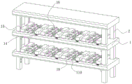
Fig. 1 is a perspective view of a structure of a shelving plate of the application.
Figure 2 is a cross-sectional view of the support post structure of the present application.
Fig. 3 is a cross-sectional view of the structure of the shelf board of the present application.
Fig. 4 is a sectional view of the fixed mount structure of the present application.
Fig. 5 is a structural perspective view of a second spring of the present application.
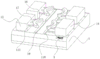
Fig. 6 is a perspective view of the slide mount of the present application.
Description of reference numerals: 1. placing a shelf plate; 11. fixing the rod; 12. a chute; 13. fixing the mounting seat; 14. a sliding mounting seat; 15. a circular groove; 16. a card slot; 17. a round bar; 18. a splint; 19. a first draining rod; 110. a second draining rod; 111. clamping a plate; 112. a first spring; 113. a limiting plate; 114. a second spring; 115. a limiting groove; 116. a limiting rod; 2. a support column; 3. a rotating gear; 4. a rack bar; 41. a connecting plate; 5. a motor; 6. a threaded rod.
Detailed Description
The present application is described in further detail below with reference to figures 1-6.
Referring to fig. 1-6, a draining movable cup holder comprises a placing frame plate 1 and a supporting column 2, wherein the inside of the placing frame plate 1 is connected with the outer surface of the supporting column 2 in a sliding mode, an adjusting device is arranged inside the placing frame plate 1 and comprises a rotating gear 3, a toothed bar 4, a motor 5 and a threaded rod 6, the rotating gear 3 rotates to drive the toothed bar 4 to move horizontally, the motor 5 controls the threaded rod 6 to rotate, and the threaded rod 6 rotates in the placing frame plate 1 to drive the placing frame plate 1 to move up and down.
Referring to fig. 3, the fixing rod 11 is fixedly connected to the inside of the shelf board 1, the rotating gear 3 rotates to be sleeved on the outer surface of the fixing rod 11, the sliding groove 12 is formed in the inside of the shelf board 1, the toothed bar 4 is slidably connected to the inside of the sliding groove 12, the outer surface of the toothed bar 4 is meshed with the outer surface of the rotating gear 3, the rotating gear 3 is sleeved outside the fixing rod 11 to rotate, and the toothed bar 4 can be driven to horizontally move in the shelf board 1.
Referring to fig. 2, motor 5 fixed mounting is in the inside of support column 2, and two motors 5 use the axis of support column 2 to be the symmetric distribution as the symmetric center, and 6 fixed connection of threaded rod are on motor 5's pivot top, and the surface of threaded rod 6 and the inside threaded connection who puts frame plate 1, motor 5 start-up let the pivot drive threaded rod 6 rotate, and threaded rod 6 can drive and put frame plate 1 and move from top to bottom stably, is convenient for adjust the height of putting frame plate 1.
As shown in fig. 1, fig. 4 and fig. 6, fixed surface installs fixed mounting seat 13 on putting frame plate 1, the last sliding surface who puts frame plate 1 has sliding mounting seat 14, circular slot 15 and draw-in groove 16 have all been seted up to sliding mounting seat 14 and fixed mounting seat 13's inside, circular slot 15's inside slip is pegged graft and is had round bar 17, round bar 17's top fixedly connected with splint 18, put the first waterlogging caused by excessive rainfall pole 19 of the last fixed surface of frame plate 1, sliding mounting seat 14's outer fixed surface is connected with second waterlogging caused by excessive rainfall pole 110, the interval of two mounts is changed according to the position of adjusting sliding mounting seat 14, be convenient for fix the drinking cup of equidimension not.
As shown in fig. 4, a clamping plate 111 is fixedly connected to the outer surface of the clamping plate 18, the outer surface of the clamping plate 111 is slidably connected to the inner wall of the clamping groove 16, a first spring 112 is fixedly connected to the other end of the round rod 17, the other end of the first spring 112 is fixedly connected to the inner wall of the round groove 15, the elastic force of the first spring 112 enables the two clamping plates 18 to clamp the water cup, and the clamping plate 111 is clamped in the clamping groove 16, so that the clamping plates 18 can keep moving horizontally and do not separate from the insides of the two mounting seats.
As shown in fig. 5, the upper surface of ratch 4 is fixedly connected with connecting plate 41, the upper surface of connecting plate 41 is fixedly connected with the lower surface of slidable mounting seat 14, the inside of putting frame plate 1 slides and is pegged graft and has limiting plate 113, the front end of limiting plate 113 slides and pegs graft at the surface of rotating gear 3, the outer fixed surface of limiting plate 113 is connected with second spring 114, the other end of second spring 114 and the inside fixed connection of putting frame plate 1, limiting groove 115 has been seted up to the inside of putting frame plate 1, the equal fixedly connected with gag lever post 116 in both sides of limiting plate 113, gag lever post 116 sliding connection is in the inside of gag lever post 115, second spring 114 lets limiting plate 113 card at the surface of rotating gear 3, restriction rotating gear 3 rotates, so as to guarantee the stability of slidable mounting seat 14, gag lever post 116 card is in gag lever groove 115, guarantee that limiting plate 113 keeps steadily sliding.
Through setting up adjusting device, starter motor 5 lets the pivot drive threaded rod 6 rotate, threaded rod 6 can drive and put frame plate 1 and stably move from top to bottom, it is when carrying out the waterlogging caused by excessive rainfall to be convenient for adjust the height of putting frame plate 1, rotate bull gear 3 according to the size of drinking cup earlier, drive bull gear 4 horizontal migration, bull gear 4 drives fixed plate and sliding installation seat 14 and moves, and then adjust the interval of fixed mounting seat 13 and sliding installation seat 14, then insert the drinking cup between two splint 18, splint 18 front end posts the cushion, so as to avoid the drinking cup to be pressed from both sides bad, the elasticity of first spring 112 lets two splint 18 press from both sides the drinking cup tightly, cardboard 111 card is in draw-in groove 16, let splint 18 can keep horizontal migration and not deviate from two mount pads inside, the upper surface of first waterlogging caused by excessive rainfall frame and second waterlogging caused by excessive rainfall frame is arranged in the below of drinking cup, let the drinking cup lower extreme and frame plate 1 keep a certain distance to carry out the waterlogging caused by excessive rainfall, the elasticity limiting plate 113 card of second spring 114 lets the card restrict outside bull gear 3, it rotates to restrict the rotation of bull gear 3 to guarantee that the sliding installation seat 14, so as to guarantee the stable mounting bar card reaches 115, it is convenient for the drinking cup to keep the limiting plate to carry out the stable size of smashing to carry out the waterlogging caused by the stable waterlogging caused by the water dropping.
The working principle is as follows: the starting motor 5 enables the rotating shaft to drive the threaded rod 6 to rotate, the threaded rod 6 can drive the placing frame plate 1 to stably move up and down, the height of the placing frame plate 1 can be conveniently adjusted when water is drained, the rotating gear 3 is rotated according to the size of a water cup firstly, the toothed rod 4 is driven to horizontally move, the toothed rod 4 drives the fixed plate and the sliding installation seat 14 to move, the distance between the fixed installation seat 13 and the sliding installation seat 14 is adjusted, the water cup is then inserted between the two clamping plates 18 in an inverted mode, the front end of each clamping plate 18 is pasted with a cushion, so that the water cup is prevented from being damaged by clamping, the elasticity of the first spring 112 enables the two clamping plates 18 to clamp the water cup, the clamping plate 111 is clamped in the clamping groove 16, the clamping plate 18 can keep horizontal movement and does not separate from the two installation seats, the upper surface of the first water draining frame and the second water draining frame is arranged below the water cup, the lower end of the water cup and the placing frame plate 1 are kept at a certain distance for water draining, the elasticity of the second spring 114 enables the limiting plate 113 to be clamped outside the rotating gear 3, so that the sliding of the limiting plate is kept stable in the limiting groove 113.
Claims (6)
1. The utility model provides a waterlogging caused by excessive rainfall activity glass stand, is including putting frame plate (1) and support column (2), its characterized in that: put the inside of frame plate (1) and the surface sliding connection of support column (2), the inside of putting frame plate (1) is provided with adjusting device, adjusting device includes change gear (3), ratch (4), motor (5) and threaded rod (6), change gear (3) are rotated and are driven ratch (4) level and move, motor (5) control threaded rod (6) are rotated, threaded rod (6) are putting frame plate (1) internal rotation drive and are put frame plate (1) and reciprocate.
2. The draining movable cup holder of claim 1, wherein: put inside fixedly connected with dead lever (11) of frame plate (1), running gear (3) rotate and cup joint the surface at dead lever (11), put the inside of frame plate (1) and seted up spout (12), ratch (4) sliding connection is in the inside of spout (12), the surface meshing of ratch (4) and running gear (3).
3. The draining movable cup holder of claim 1, wherein: motor (5) fixed mounting is in the inside of support column (2), two the axis that motor (5) used support column (2) is the symmetric distribution for the centre of symmetry, threaded rod (6) fixed connection is on the pivot top of motor (5), the surface of threaded rod (6) and the inside threaded connection who puts frame plate (1).
4. The draining movable cup holder of claim 1, wherein: put the last fixed surface of frame plate (1) and install fixed mounting seat (13), the last sliding surface who puts frame plate (1) is connected with sliding mounting seat (14), circular slot (15) and draw-in groove (16) have all been seted up to sliding mounting seat (14) and the inside of fixed mounting seat (13), the inside slip of circular slot (15) is pegged graft and is had round bar (17), the top fixedly connected with splint (18) of round bar (17), put the first pole (19) of driping of last fixed surface of frame plate (1) connection, the outer fixed surface of sliding mounting seat (14) is connected with second pole (110) of driping.
5. The draining movable cup holder of claim 4, wherein: the clamping plate (111) is fixedly connected to the outer surface of the clamping plate (18), the outer surface of the clamping plate (111) is in sliding connection with the inner wall of the clamping groove (16), the first spring (112) is fixedly connected to the other end of the round rod (17), and the other end of the first spring (112) is fixedly connected with the inner wall of the round groove (15).
6. The draining movable cup holder of claim 4, wherein: the last fixed surface of ratch (4) is connected with connecting plate (41), the upper surface of connecting plate (41) is connected with the lower fixed surface of slidable mounting seat (14), the inside of putting frame plate (1) slides and pegs graft there is limiting plate (113), the front end of limiting plate (113) slides and pegs graft at the surface of rolling gear (3), the outer fixed surface of limiting plate (113) is connected with second spring (114), the other end of second spring (114) and the inside fixed connection who puts frame plate (1), spacing groove (115) have been seted up to the inside of putting frame plate (1), the equal fixedly connected with gag lever post (116) in both sides of limiting plate (113), gag lever post (116) sliding connection is in the inside of spacing groove (115).
Priority Applications (1)
| Application Number | Priority Date | Filing Date | Title |
|---|---|---|---|
| CN202221397836.6U CN218683629U (en) | 2022-06-06 | 2022-06-06 | Draining movable cup holder |
Applications Claiming Priority (1)
| Application Number | Priority Date | Filing Date | Title |
|---|---|---|---|
| CN202221397836.6U CN218683629U (en) | 2022-06-06 | 2022-06-06 | Draining movable cup holder |
Publications (1)
| Publication Number | Publication Date |
|---|---|
| CN218683629U true CN218683629U (en) | 2023-03-24 |
Family
ID=85607235
Family Applications (1)
| Application Number | Title | Priority Date | Filing Date |
|---|---|---|---|
| CN202221397836.6U Active CN218683629U (en) | 2022-06-06 | 2022-06-06 | Draining movable cup holder |
Country Status (1)
| Country | Link |
|---|---|
| CN (1) | CN218683629U (en) |
-
2022
- 2022-06-06 CN CN202221397836.6U patent/CN218683629U/en active Active
Similar Documents
| Publication | Publication Date | Title |
|---|---|---|
| CN208807870U (en) | A kind of service plate storing unit for kitchen use | |
| CN211295805U (en) | Liftable switch board is used in electric power marketing | |
| CN112369843B (en) | Assembled display cabinet for living room | |
| CN214342128U (en) | Adjustable type library's bookshelf wiping arrangement | |
| CN218768671U (en) | Propaganda is with removing show shelf | |
| CN221382918U (en) | Data storage and query device | |
| CN223691388U (en) | Supporting device capable of adjusting height of glass rack for refrigerator | |
| CN218164592U (en) | Movable multifunctional bookcase | |
| CN220988217U (en) | Multifunctional auditorium chair with stable structure | |
| CN218441648U (en) | Display raise frame | |
| CN219895080U (en) | Wine cabinet integral internal shelf structure | |
| CN220442229U (en) | Multifunctional spliced table storage cabinet | |
| CN219206297U (en) | Portable tea cabinet | |
| CN217941020U (en) | Computer display screen is with clean dust collector | |
| CN219250441U (en) | Quick-mounting rack | |
| CN111955917A (en) | Forced relaxation type book support frame for reading | |
| CN222916080U (en) | Simple portable mobile phone support | |
| CN222159141U (en) | Flattening machine for pet food | |
| CN219088842U (en) | Height-adjustable display stand | |
| CN223289789U (en) | A milling cutter placement rack for easy and regular placement | |
| CN222777206U (en) | Adjustable water receiving rack structure of water dispenser | |
| CN215411043U (en) | Multifunctional television bracket base | |
| CN221489610U (en) | A double-layer staggered folding three-dimensional photo frame | |
| CN219134361U (en) | Vertical parking frame for mountain bike | |
| CN220590115U (en) | Material bearing table of high-speed refrigerated centrifuge for biological detection |
Legal Events
| Date | Code | Title | Description |
|---|---|---|---|
| GR01 | Patent grant | ||
| GR01 | Patent grant |