CN218676474U - Portable wireless storage device - Google Patents
Portable wireless storage device Download PDFInfo
- Publication number
- CN218676474U CN218676474U CN202223219080.9U CN202223219080U CN218676474U CN 218676474 U CN218676474 U CN 218676474U CN 202223219080 U CN202223219080 U CN 202223219080U CN 218676474 U CN218676474 U CN 218676474U
- Authority
- CN
- China
- Prior art keywords
- storage device
- housing
- casing
- fixedly connected
- wireless storage
- Prior art date
- Legal status (The legal status is an assumption and is not a legal conclusion. Google has not performed a legal analysis and makes no representation as to the accuracy of the status listed.)
- Expired - Fee Related
Links
- 230000001681 protective effect Effects 0.000 claims abstract description 34
- 238000009434 installation Methods 0.000 claims abstract description 8
- 239000000463 material Substances 0.000 claims description 4
- VYPSYNLAJGMNEJ-UHFFFAOYSA-N Silicium dioxide Chemical compound O=[Si]=O VYPSYNLAJGMNEJ-UHFFFAOYSA-N 0.000 claims 1
- 239000000741 silica gel Substances 0.000 claims 1
- 229910002027 silica gel Inorganic materials 0.000 claims 1
- 239000000428 dust Substances 0.000 description 10
- 238000010586 diagram Methods 0.000 description 4
- 238000009825 accumulation Methods 0.000 description 3
- 238000000034 method Methods 0.000 description 2
- 229920001296 polysiloxane Polymers 0.000 description 2
- 230000000203 accumulation affect Effects 0.000 description 1
- 230000009286 beneficial effect Effects 0.000 description 1
- 230000005540 biological transmission Effects 0.000 description 1
- 239000003153 chemical reaction reagent Substances 0.000 description 1
- 238000007796 conventional method Methods 0.000 description 1
- 230000007812 deficiency Effects 0.000 description 1
- 230000000694 effects Effects 0.000 description 1
- 238000002474 experimental method Methods 0.000 description 1
- 230000003116 impacting effect Effects 0.000 description 1
- 230000007774 longterm Effects 0.000 description 1
- 238000004519 manufacturing process Methods 0.000 description 1
Images


Landscapes
- Telephone Set Structure (AREA)
Abstract
本实用新型公开了一种便携式无线存储装置,包括壳体,所述壳体内部的后端安装有主板,所述主板前端的底部安装有多媒体处理器,所述壳体的一侧安装有控制面板,所述壳体另一侧的顶部安装有天线,所述天线的一侧和主板的一侧固定连接。通过在壳体的外部设置有防护结构,在使用时将保护套壳套接在壳体的外部,同时将安装套槽分别套接在固定卡块的外部,以此将保护套壳固定在装置的外部,通过保护套壳对存储装置进行保护,防止外物撞击损坏存储装置,影响其正常运行,有效的提高了无线储存装置的防护性能,并且还便于对保护套壳进行拆卸,并且通过便携提带还便于提拉无线存储装置携带,更加便于使用无线储存装置。
The utility model discloses a portable wireless storage device, which comprises a casing, a main board is installed at the rear end of the inside of the casing, a multimedia processor is installed at the bottom of the front end of the main board, and a control device is installed at one side of the casing. An antenna is installed on the top of the other side of the housing, and one side of the antenna is fixedly connected to one side of the main board. By providing a protective structure on the outside of the housing, the protective sleeve is sleeved on the outside of the housing during use, and at the same time, the installation sleeve grooves are respectively sleeved on the outside of the fixing block, so that the protective sleeve is fixed on the device. The outside of the storage device is protected by the protective case to prevent the impact of foreign objects from damaging the storage device and affecting its normal operation. The carrying strap is also convenient for lifting and carrying the wireless storage device, making it easier to use the wireless storage device.
Description
技术领域technical field
本实用新型涉及无线储存技术领域,特别是涉及一种便携式无线存储装置。The utility model relates to the technical field of wireless storage, in particular to a portable wireless storage device.
背景技术Background technique
无线储存装置是便于对资源进行管理且具有无线传输功能的移动设备,在信息化的今天电子设备广泛应用在人们生活生产的方方面面,而无线存储设备则更加便于人们对电子设备内日益增多的各种需要存储的资源进行管理;Wireless storage devices are mobile devices that are convenient for resource management and have wireless transmission functions. Electronic devices are widely used in all aspects of people's life and production in today's informationized world, and wireless storage devices are more convenient for people to manage the increasing variety of electronic devices. A resource that needs to be stored for management;
然而无线储存设备在应用的过程中容易受到撞击损坏内部电子元器件,且无线存储设备为盒体结构,长时间使用后接线端容易进尘长此以往造成积尘影响插拔稳固性,存在着防护性不足且不便携带以及不能对接线插口进行防尘保护的技术问题。However, the wireless storage device is vulnerable to impact damage to the internal electronic components during the application process, and the wireless storage device is a box structure. After a long period of use, the terminals are prone to dust. If things go on like this, the dust accumulation will affect the stability of plugging and unplugging, and there is protection. Insufficient and inconvenient to carry and the technical problem of not being able to protect the wiring socket from dust.
实用新型内容Utility model content
为了克服现有技术的不足,本实用新型提供一种便携式无线存储装置,能解决容易受到撞击损坏内部电子元器件,且无线存储设备为盒体结构,长时间使用后接线端容易进尘长此以往造成积尘影响插拔稳固性,存在着防护性不足且不便携带以及不能对接线插口进行防尘保护的技术问题。In order to overcome the deficiencies of the prior art, the utility model provides a portable wireless storage device, which can solve the problem that the internal electronic components are easily damaged by impact, and the wireless storage device is a box structure, and the terminal is easy to enter dust after long-term use. Dust accumulation affects the stability of plugging and unplugging, and there are technical problems such as insufficient protection, inconvenient portability, and inability to protect the wiring socket from dust.
为解决上述技术问题,本实用新型提供如下技术方案:一种便携式无线存储装置,包括壳体,所述壳体内部的后端安装有主板,所述主板前端的底部安装有多媒体处理器,所述壳体的一侧安装有控制面板,所述壳体另一侧的顶部安装有天线,所述天线的一侧和主板的一侧固定连接,所述壳体另一侧的底部安装有USB接线端板,所述壳体的外部设置有防护结构,所述壳体另一侧后端的底部设置有防尘结构。In order to solve the above-mentioned technical problems, the utility model provides the following technical solutions: a portable wireless storage device, including a housing, a main board is installed at the rear end inside the housing, and a multimedia processor is installed at the bottom of the front end of the main board. A control panel is installed on one side of the housing, an antenna is installed on the top of the other side of the housing, one side of the antenna is fixedly connected to one side of the main board, and a USB port is installed on the bottom of the other side of the housing. As for the terminal plate, a protective structure is arranged on the outside of the casing, and a dustproof structure is arranged on the bottom of the rear end on the other side of the casing.
作为本实用新型的一种优选技术方案,所述防护结构包括保护套壳,所述保护套壳套接在壳体的外部,所述保护套壳内部的两端分别固定连接有固定卡块,所述壳体两端的中间位置处分别固定连接有安装套槽。As a preferred technical solution of the present invention, the protective structure includes a protective casing, the protective casing is sleeved on the outside of the housing, and the two ends inside the protective casing are respectively fixedly connected with fixed blocks, The middle positions of both ends of the housing are respectively fixedly connected with installation sleeve grooves.
作为本实用新型的一种优选技术方案,所述防尘结构包括连接片,所述连接片设置在壳体另一侧后端的底部,所述连接片一侧的两端和中间位置处分别固定连接有连接带,所述连接片前端的顶部和底部分别固定连接有防尘堵头。As a preferred technical solution of the present invention, the dust-proof structure includes a connecting piece, the connecting piece is arranged at the bottom of the rear end on the other side of the housing, and the two ends and the middle position on one side of the connecting piece are respectively fixed A connecting belt is connected, and the top and bottom of the front end of the connecting piece are respectively fixedly connected with dust-proof plugs.
作为本实用新型的一种优选技术方案,所述固定卡块在保护套壳的内部呈对称设置,所述保护套壳前端和后端一侧的中间位置处分别固定连接有便携提带。As a preferred technical solution of the present invention, the fixed blocks are arranged symmetrically inside the protective case, and the middle positions of the front end and the rear end of the protective case are respectively fixedly connected with portable straps.
作为本实用新型的一种优选技术方案,所述连接带设置有三组,所述连接带由硅胶材料制成,所述连接带的一侧分别和壳体另一侧后端的底部固定连接。As a preferred technical solution of the present invention, there are three sets of connecting straps, the connecting straps are made of silicone material, and one side of the connecting straps is respectively fixedly connected to the bottom of the rear end of the other side of the casing.
作为本实用新型的一种优选技术方案,所述主板前端一侧的顶部安装有信号处理器,所述主板前端另一侧的顶部安装有存储硬盘。As a preferred technical solution of the present invention, a signal processor is installed on the top of one side of the front end of the main board, and a storage hard disk is installed on the top of the other front end of the main board.
与现有技术相比,本实用新型能达到的有益效果是:Compared with the prior art, the beneficial effects that the utility model can achieve are:
1、通过在壳体的外部设置有防护结构,在使用时将保护套壳套接在壳体的外部,同时将安装套槽分别套接在固定卡块的外部,以此将保护套壳固定在装置的外部,通过保护套壳对存储装置进行保护,防止外物撞击损坏存储装置,影响其正常运行,有效的提高了无线储存装置的防护性能,并且还便于对保护套壳进行拆卸,并且通过便携提带还便于提拉无线存储装置携带,更加便于使用无线储存装置;1. By providing a protective structure on the outside of the housing, the protective sleeve is sleeved on the outside of the housing during use, and at the same time, the installation sleeves are respectively sleeved on the outside of the fixed block, so as to fix the protective sleeve On the outside of the device, the storage device is protected by a protective case to prevent the impact of foreign objects from damaging the storage device and affecting its normal operation, which effectively improves the protection performance of the wireless storage device and facilitates the removal of the protective case, and The portable carrying strap is also convenient for lifting and carrying the wireless storage device, making it easier to use the wireless storage device;
2、通过在壳体另一侧后端的底部设置有防尘结构,无线装置在不使用时将固定连接在连接片前端的防尘堵头插接进USB接线端板插口内部,以此将未插接线束的USB接线端板插口堵住,防止灰尘进入接口内部造成积尘影响接线稳定性,并且通过由硅胶柔性材料制成的连接带将连接片与壳体固定连接,以此将防尘堵头与装置连接,以防拔出时防尘堵头遗失,并且还便于对防尘堵头进行插拔,可操作性强。2. By setting a dust-proof structure at the bottom of the rear end on the other side of the housing, when the wireless device is not in use, insert the dust-proof plug fixedly connected to the front end of the connecting piece into the socket of the USB terminal board, so as to close the The socket of the USB terminal board for plugging in the wiring harness is blocked to prevent dust from entering the interface and causing dust accumulation to affect the stability of the wiring. The plug is connected with the device to prevent the dust-proof plug from being lost when it is pulled out, and it is also convenient to insert and remove the dust-proof plug, which has strong operability.
附图说明Description of drawings
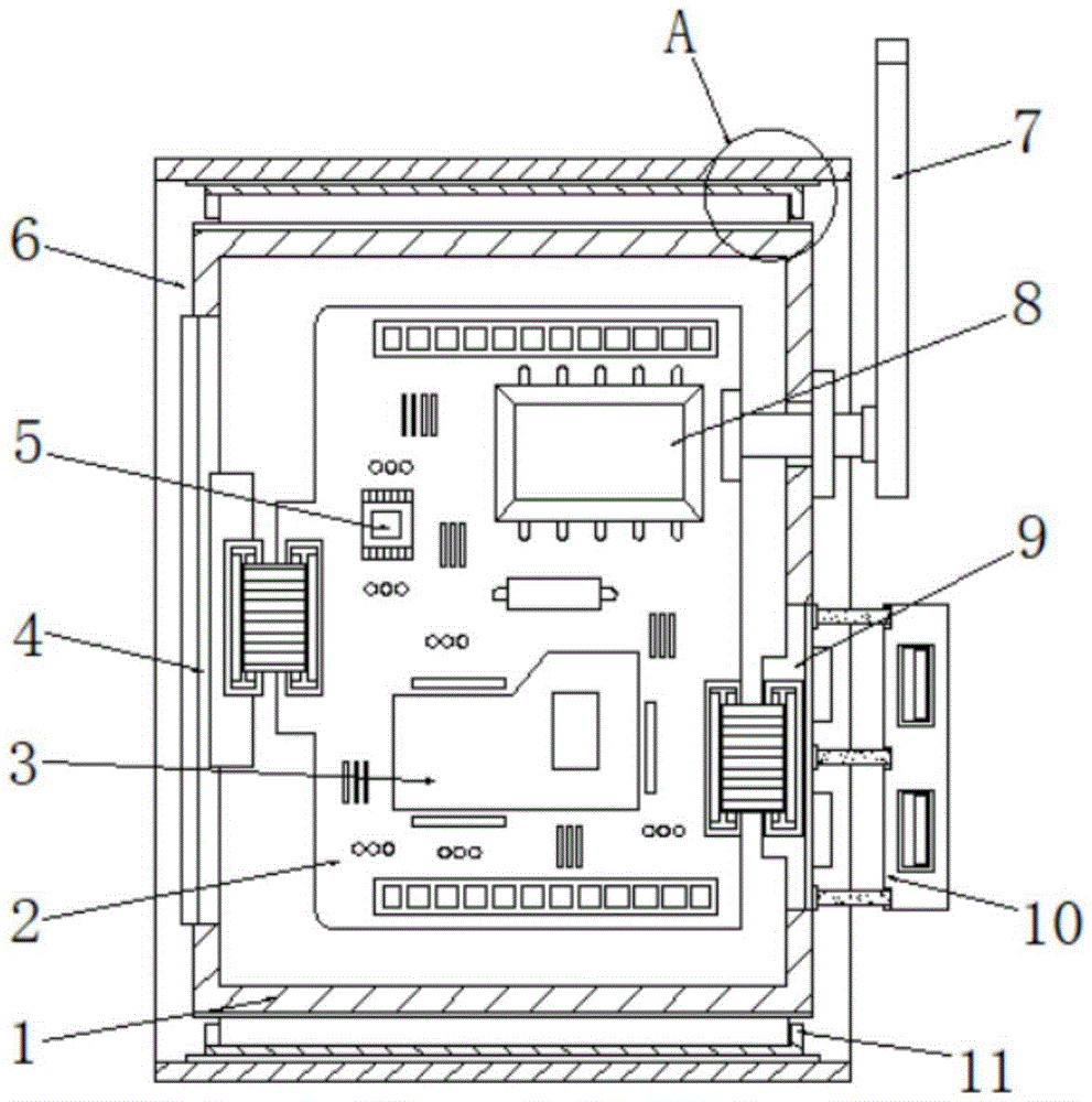
图1为本实用新型的正视剖面结构示意图;Fig. 1 is the front view sectional structure schematic diagram of the utility model;
图2为本实用新型的保护套壳侧视结构示意图;Fig. 2 is a side view structural schematic diagram of the protective sleeve of the present invention;
图3为本实用新型的图1中A处放大结构示意图;Fig. 3 is the schematic diagram of enlarged structure at A place in Fig. 1 of the present utility model;
图4为本实用新型的连接片正视局部结构示意图。Fig. 4 is a schematic diagram of a front view of a partial structure of the connecting piece of the present invention.
其中:1、壳体;2、主板;3、多媒体处理器;4、控制面板;5、信号处理器;6、保护套壳;7、天线;8、存储硬盘;9、USB接线端板;10、连接片;11、安装套槽;12、便携提带;13、固定卡块;14、防尘堵头;15、连接带。Among them: 1. Shell; 2. Main board; 3. Multimedia processor; 4. Control panel; 5. Signal processor; 6. Protective casing; 7. Antenna; 8. Storage hard disk; 9. USB terminal board; 10. Connecting piece; 11. Installation sleeve groove; 12. Portable strap; 13. Fixed block; 14. Dust-proof plug; 15. Connecting belt.
具体实施方式Detailed ways
为了使本实用新型实现的技术手段、创作特征、达成目的与功效易于明白了解,下面结合具体实施例,进一步阐述本实用新型,但下述实施例仅仅为本实用新型的优选实施例,并非全部。基于实施方式中的实施例,本领域技术人员在没有做出创造性劳动的前提下所获得其它实施例,都属于本实用新型的保护范围。下述实施例中的实验方法,如无特殊说明,均为常规方法,下述实施例中所用的材料、试剂等,如无特殊说明,均可从商业途径得到。In order to make the technical means, creative features, goals and effects of the utility model realized easy to understand, the utility model will be further elaborated below in conjunction with specific examples, but the following examples are only preferred embodiments of the utility model, not all . Based on the examples in the implementation manners, other examples obtained by those skilled in the art without making creative efforts all belong to the protection scope of the present utility model. The experimental methods in the following examples, unless otherwise specified, are conventional methods, and the materials, reagents, etc. used in the following examples, unless otherwise specified, can be obtained from commercial sources.
实施例Example
请参照图1-4所示,本实用新型提供一种便携式无线存储装置,包括壳体1,壳体1内部的后端安装有主板2,主板2前端的底部安装有多媒体处理器3,壳体1的一侧安装有控制面板4,壳体1另一侧的顶部安装有天线7,天线7的一侧和主板2的一侧固定连接,壳体1另一侧的底部安装有USB接线端板9,壳体1的外部设置有防护结构,壳体1另一侧后端的底部设置有防尘结构,主板2前端一侧的顶部安装有信号处理器5,主板2前端另一侧的顶部安装有存储硬盘8;Please refer to Figures 1-4, the utility model provides a portable wireless storage device, including a
作为本实施例进一步的实施方式,如图1、图2和图3所示,防护结构包括保护套壳6,保护套壳6套接在壳体1的外部,保护套壳6内部的两端分别固定连接有固定卡块13,壳体1两端的中间位置处分别固定连接有安装套槽11,将安装套槽11分别套接在固定卡块13的外部,以此将保护套壳6固定在装置的外部,通过保护套壳6对存储装置进行保护,防止外物撞击损坏存储装置,固定卡块13在保护套壳6的内部呈对称设置,保护套壳6前端和后端一侧的中间位置处分别固定连接有便携提带12,通过便携提带12还便于提拉无线存储装置携带,更加便于使用无线储存装置;As a further implementation of this embodiment, as shown in Fig. 1, Fig. 2 and Fig. 3, the protective structure includes a
作为本实施例进一步的实施方式,如图1和图4所示,防尘结构包括连接片10,连接片10设置在壳体1另一侧后端的底部,连接片10一侧的两端和中间位置处分别固定连接有连接带15,连接片10前端的顶部和底部分别固定连接有防尘堵头14,将防尘堵头14插接进未插接线束的USB接线端板9插口内部,以此将USB接线端板9插口堵住,防止灰尘进入接口内部造成积尘影响接线稳定性,连接带15设置有三组,连接带15由硅胶材料制成,通过连接带15以防拔出时防尘堵头14遗失,并且还便于对防尘堵头14进行插拔,连接带15的一侧分别和壳体1另一侧后端的底部固定连接;As a further implementation of this embodiment, as shown in Figure 1 and Figure 4, the dustproof structure includes a connecting
在使用时无线存储装置时,将保护套壳6套接在壳体1的外部,同时将安装套槽11分别套接在固定卡块13的外部,以此将保护套壳6固定在装置的外部,通过USB接线端板9便于对装置进行接线安装,通过控制面板4可方便使用者对存储装置进行控制,通过存储硬盘8对使用者需要管理的资源进行储存,使用完装置后将连接线拔出USB接线端板9,随后将防尘堵头14插接进未插接线束的USB接线端板9插口内部防尘,使用便携提带12方便使用者携带装置。When using the wireless storage device, the
在本实用新型中,除非另有明确的规定和限定,第一特征在第二特征之“上”或之“下”可以包括第一和第二特征直接接触,也可以包括第一和第二特征不是直接接触而是通过它们之间的另外的特征接触。而且,第一特征在第二特征“之上”、“上方”和“上面”包括第一特征在第二特征正上方和斜上方,或仅仅表示第一特征水平高度高于第二特征。第一特征在第二特征“之下”、“下方”和“下面”包括第一特征在第二特征正下方和斜下方,或仅仅表示第一特征水平高度小于第二特征。In the present invention, unless otherwise clearly specified and limited, a first feature being "on" or "below" a second feature may include direct contact between the first and second features, and may also include the first and second features being in direct contact with each other. The features are not in direct contact but through another feature between them. Moreover, "above", "above" and "above" the first feature on the second feature include that the first feature is directly above and obliquely above the second feature, or simply means that the first feature is horizontally higher than the second feature. "Below", "beneath" and "under" the first feature to the second feature include that the first feature is directly below and obliquely below the second feature, or simply means that the first feature has a lower level than the second feature.
以上显示和描述了本实用新型的基本原理、主要特征和本实用新型的优点。本行业的技术人员应该了解,本实用新型不受上述实施例的限制,上述实施例和说明书中描述的仅为本实用新型的优选例,并不用来限制本实用新型,在不脱离本实用新型精神和范围的前提下,本实用新型还会有各种变化和改进,这些变化和改进都落入要求保护的本实用新型范围内。本实用新型要求保护范围由所附的权利要求书及其等效物界定。The basic principles, main features and advantages of the present utility model have been shown and described above. Those skilled in the industry should understand that the utility model is not limited by the above-mentioned embodiments. The above-mentioned embodiments and descriptions are only preferred examples of the utility model, and are not used to limit the utility model. Without departing from the utility model Under the premise of the spirit and scope, the utility model also has various changes and improvements, and these changes and improvements all fall within the scope of the claimed utility model. The scope of protection required by the utility model is defined by the appended claims and their equivalents.
Claims (6)
Priority Applications (1)
| Application Number | Priority Date | Filing Date | Title |
|---|---|---|---|
| CN202223219080.9U CN218676474U (en) | 2022-12-01 | 2022-12-01 | Portable wireless storage device |
Applications Claiming Priority (1)
| Application Number | Priority Date | Filing Date | Title |
|---|---|---|---|
| CN202223219080.9U CN218676474U (en) | 2022-12-01 | 2022-12-01 | Portable wireless storage device |
Publications (1)
| Publication Number | Publication Date |
|---|---|
| CN218676474U true CN218676474U (en) | 2023-03-21 |
Family
ID=85542070
Family Applications (1)
| Application Number | Title | Priority Date | Filing Date |
|---|---|---|---|
| CN202223219080.9U Expired - Fee Related CN218676474U (en) | 2022-12-01 | 2022-12-01 | Portable wireless storage device |
Country Status (1)
| Country | Link |
|---|---|
| CN (1) | CN218676474U (en) |
-
2022
- 2022-12-01 CN CN202223219080.9U patent/CN218676474U/en not_active Expired - Fee Related
Similar Documents
| Publication | Publication Date | Title |
|---|---|---|
| CN217788897U (en) | Semiconductor memory device | |
| CN204836485U (en) | Blue -tooth earphone | |
| CN214254874U (en) | Dustproof connector | |
| CN206498051U (en) | A smart USB data cable | |
| CN216436343U (en) | Multi-functional trinity flexible data line | |
| CN213024130U (en) | Industrial personal computer and data interface protection device thereof | |
| CN202189987U (en) | Multifunctional portable mobile converter for converting USB3.0 (Universal Serial Bus) into eSATA (external Serial Advanced Technology Attachment) | |
| CN221886488U (en) | Wireless transceiver | |
| CN207663355U (en) | A kind of fixed equipment for protecting computer network connection end | |
| CN224053507U (en) | TYPE-C male connector | |
| CN208142482U (en) | A kind of RJ45 connector | |
| CN206758720U (en) | An electronic connector for a mini coaxial cable | |
| CN221961364U (en) | Desktop concentrator | |
| CN204407605U (en) | Electronic equipment | |
| CN221960482U (en) | Server | |
| CN211929843U (en) | Interface conversion device and mobile phone protective case for electronic equipment | |
| CN205353856U (en) | Notebook computer with dustproof USB interface takes precautions against earthquakes | |
| CN219392955U (en) | USB hard disk box capable of reconnecting without plugging data line | |
| CN221407915U (en) | Joint converter | |
| CN213302978U (en) | Portable mini computer host | |
| CN205754700U (en) | A set-top box with voice input function | |
| CN211556220U (en) | Computer motherboard interface conversion equipment | |
| CN222282443U (en) | A USB connector with switch | |
| CN223141116U (en) | Novel wiring terminal of electric connector | |
| CN220672944U (en) | Mobile phone connector with waterproof function |
Legal Events
| Date | Code | Title | Description |
|---|---|---|---|
| GR01 | Patent grant | ||
| GR01 | Patent grant | ||
| CF01 | Termination of patent right due to non-payment of annual fee |
Granted publication date: 20230321 |
|
| CF01 | Termination of patent right due to non-payment of annual fee |