CN218664797U - Foil pole roll caching device - Google Patents
Foil pole roll caching device Download PDFInfo
- Publication number
- CN218664797U CN218664797U CN202222964768.3U CN202222964768U CN218664797U CN 218664797 U CN218664797 U CN 218664797U CN 202222964768 U CN202222964768 U CN 202222964768U CN 218664797 U CN218664797 U CN 218664797U
- Authority
- CN
- China
- Prior art keywords
- block
- pole roll
- foil pole
- foil
- buffer device
- Prior art date
- Legal status (The legal status is an assumption and is not a legal conclusion. Google has not performed a legal analysis and makes no representation as to the accuracy of the status listed.)
- Active
Links
Images


Classifications
-
- Y—GENERAL TAGGING OF NEW TECHNOLOGICAL DEVELOPMENTS; GENERAL TAGGING OF CROSS-SECTIONAL TECHNOLOGIES SPANNING OVER SEVERAL SECTIONS OF THE IPC; TECHNICAL SUBJECTS COVERED BY FORMER USPC CROSS-REFERENCE ART COLLECTIONS [XRACs] AND DIGESTS
- Y02—TECHNOLOGIES OR APPLICATIONS FOR MITIGATION OR ADAPTATION AGAINST CLIMATE CHANGE
- Y02E—REDUCTION OF GREENHOUSE GAS [GHG] EMISSIONS, RELATED TO ENERGY GENERATION, TRANSMISSION OR DISTRIBUTION
- Y02E60/00—Enabling technologies; Technologies with a potential or indirect contribution to GHG emissions mitigation
- Y02E60/10—Energy storage using batteries
Landscapes
- Unwinding Webs (AREA)
Abstract
本实用新型公开了一种箔材极卷缓存装置,一种箔材极卷缓存装置,其特征在于:包括旋转固定块、安装架、支撑杆和辊轴,所述旋转固定块两侧连接有转轴,所述转轴可转动地安装在安装架上,所述旋转固定块的外侧设置有至少两组相对应的所述支撑杆,所述支撑杆的另一端活动插设有滑动杆;所述滑动杆上套设有弹簧,所述滑动杆内侧固定有限位块,所述弹簧设置于所述支撑杆和所述限位块之间,所述限位块内侧设置有上卡块和下卡块;所述辊轴上设置有与所述上卡块和下卡块相匹配的卡槽,所述辊轴上缠绕有极卷。本实用新型结构设计科学合理,有效保证辊轴安装时的稳定性,提高放置容量,保证了极卷本身的稳定性。
The utility model discloses a foil pole roll buffering device, which is characterized in that it comprises a rotating fixed block, a mounting frame, a support rod and a roller shaft, and two sides of the rotating fixed block are connected with A rotating shaft, the rotating shaft is rotatably installed on the mounting frame, at least two groups of corresponding support rods are arranged on the outside of the rotating fixed block, and a sliding rod is movably inserted at the other end of the support rods; A spring is sleeved on the sliding rod, and a limiting block is fixed inside the sliding rod. block; the roller shaft is provided with a slot matching the upper block and the lower block, and a pole roll is wound on the roller shaft. The utility model has a scientific and reasonable structural design, effectively ensures the stability of the roller shaft during installation, improves the placement capacity, and ensures the stability of the pole roll itself.
Description
技术领域technical field
本实用新型涉及箔材极卷存放设备技术领域,具体为一种箔材极卷缓存装置。The utility model relates to the technical field of foil pole roll storage equipment, in particular to a foil pole roll cache device.
背景技术Background technique
随着新能源的崛起,锂电池需求量增加,制片段各工序待产箔材极卷以及生产好的箔材极卷需要使用上料小车将其放置缓存架上。With the rise of new energy sources, the demand for lithium batteries has increased, and the foil coils to be produced in each process of the production process and the produced foil coils need to be placed on the buffer rack using a loading trolley.
然而现有的极卷存放装置在存放过程中缺少有效限位机构,因此极卷容易松脱,存放效果不佳;并且通常只能放置一卷箔材极卷,导致在实际生产过程中,需要大量缓存架对箔材极卷进行存放,在占用大量空间的同时,增加了公司制造成本和管理难度。为此,我们提出一种箔材极卷缓存装置。However, the existing pole roll storage device lacks an effective limit mechanism during the storage process, so the pole roll is easy to loosen, and the storage effect is not good; and usually only one roll of foil pole roll can be placed, resulting in the actual production process. A large number of buffer racks are used to store foil pole rolls, which not only takes up a lot of space, but also increases the company's manufacturing costs and management difficulties. To this end, we propose a foil pole roll cache device.
实用新型内容Utility model content
本实用新型的目的在于提供一种箔材极卷缓存装置,以解决上述背景技术中提出的问题。The purpose of this utility model is to provide a foil pole roll buffer device to solve the problems raised in the above-mentioned background technology.
为实现上述目的,本实用新型提供如下技术方案:包括旋转固定块、安装架、支撑杆和辊轴,所述旋转固定块两侧连接有转轴,所述转轴可转动地安装在所述安装架上,所述旋转固定块的外侧设置有至少两组相对应的所述支撑杆,所述支撑杆的另一端活动插设有滑动杆;所述滑动杆上套设有弹簧,所述滑动杆内侧固定有限位块,所述弹簧设置于所述支撑杆和所述限位块之间,所述限位块内侧设置有上卡块和下卡块;所述辊轴上设置有与所述上卡块和所述下卡块相匹配的卡槽,所述辊轴上缠绕有极卷。In order to achieve the above object, the utility model provides the following technical solutions: including a rotating fixed block, a mounting frame, a support rod and a roller shaft, the two sides of the rotating fixed block are connected with rotating shafts, and the rotating shafts are rotatably mounted on the mounting frame On the outside of the rotating fixed block, at least two sets of corresponding support rods are provided, and the other end of the support rods is movably inserted with a sliding rod; a spring is sleeved on the sliding rod, and the sliding rod The inner side is fixed with a limit block, the spring is arranged between the support rod and the limit block, and the inner side of the limit block is provided with an upper block and a lower block; the roller shaft is provided with a The upper block matches the lower block, and the pole roll is wound on the roller shaft.
所述辊轴上设置有与所述上卡块和下卡块相匹配的卡槽,所述辊轴上缠绕有极卷。The roller shaft is provided with slots matching the upper block and the lower block, and a pole roll is wound on the roller shaft.
优选地,所述上卡块上设置有磁铁,所述卡槽内设置有与所述磁铁相配合的铁片。Preferably, a magnet is provided on the upper clamping block, and an iron piece matched with the magnet is provided in the clamping slot.
优选地,所述下卡块内螺接有第一锁止螺杆。Preferably, a first locking screw is screwed inside the lower block.
优选地,所述辊轴上位于所述极卷两侧套设有活动套筒和限位盘,所述活动套筒侧壁螺接有第二锁止螺杆。Preferably, a movable sleeve and a limit plate are sheathed on both sides of the pole roll on the roller shaft, and a second locking screw is screwed to the side wall of the movable sleeve.
优选地,所述限位盘内侧设置有防磨片。Preferably, an anti-wear sheet is provided inside the limiting disc.
优选地,所述转轴一端通过减速器与电动机的输出轴传动连接。Preferably, one end of the rotating shaft is drive-connected with the output shaft of the motor through a reducer.
优选地,所述安装架下侧固定有支撑架。Preferably, a support frame is fixed on the lower side of the installation frame.
优选地,所述支撑架与地面的夹角设置为45°-60°。Preferably, the angle between the support frame and the ground is set at 45°-60°.
优选地,相对应的一组所述支撑杆之间通过加强杆固定连接。Preferably, a corresponding set of support rods is fixedly connected through reinforcing rods.
优选地,所述支撑杆端部与所述旋转固定块侧面对应开设有通孔,所述通孔与螺栓配合使用。Preferably, the end of the support rod is provided with a through hole corresponding to the side of the rotating fixed block, and the through hole is used in cooperation with a bolt.
与现有技术相比,本实用新型的有益效果是:Compared with the prior art, the beneficial effects of the utility model are:
1)该种箔材极卷缓存装置,结构设计简单合理,具有较强的实用性,通过在旋转固定块上集成设置多组支撑杆固定机构,可以方便上下料,且装置整体结构紧凑,缩减了占地面积,节省生产空间;1) This kind of foil pole roll buffer device has a simple and reasonable structural design and strong practicability. By integrating multiple sets of support rod fixing mechanisms on the rotating fixed block, it can facilitate loading and unloading, and the overall structure of the device is compact, reducing Reduced footprint, saving production space;
2)通过设置配合使用的滑动杆、弹簧、限位块、上卡块和下卡块等结构,可以在弹簧作用下将辊轴端部卡入对应的上卡块和下卡块内,有效保证辊轴安装时的稳定性,提高放置效果。2) By setting the sliding rod, spring, limit block, upper block and lower block and other structures used in conjunction, the end of the roller shaft can be snapped into the corresponding upper block and lower block under the action of the spring, effectively Ensure the stability of the roller shaft installation and improve the placement effect.
附图说明Description of drawings
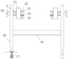
图1为本实用新型结构示意图;Fig. 1 is the structural representation of the utility model;
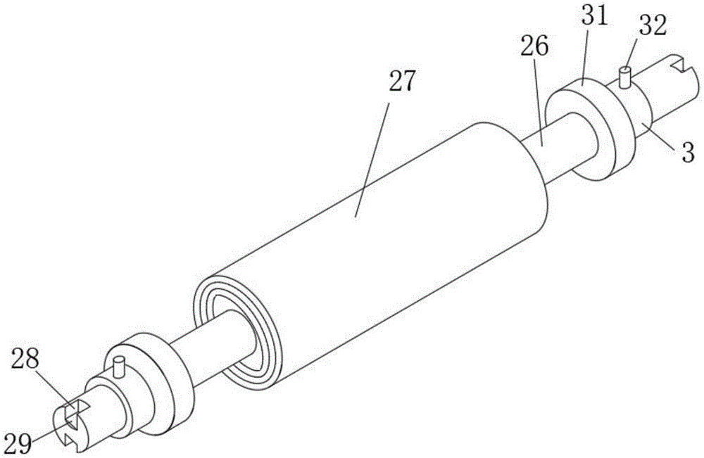
图2为本实用新型防偏机构的结构示意图;Fig. 2 is a structural schematic diagram of the anti-deviation mechanism of the present invention;
图3为本实用新型限位机构的结构示意图;Fig. 3 is the structural schematic diagram of the limit mechanism of the present invention;
图中:1-旋转固定块、11-转轴、12-安装架、13-减速器、14-电动机、15-支撑架、16-支撑杆、17-通孔、18-加强杆、19-滑动杆、2-弹簧、21-限位块、22-上卡块、23-磁铁、24-下卡块、25-第一锁止螺杆、26-辊轴、27-极卷、28-卡槽、29-铁片、3-套筒、31-限位盘、32-第二锁止螺杆。In the figure: 1-rotating fixed block, 11-rotating shaft, 12-mounting frame, 13-reducer, 14-motor, 15-supporting frame, 16-supporting rod, 17-through hole, 18-strengthening rod, 19-sliding Rod, 2-spring, 21-limit block, 22-upper block, 23-magnet, 24-lower block, 25-first locking screw, 26-roller shaft, 27-pole volume, 28-card slot , 29-iron sheet, 3-sleeve, 31-limit plate, 32-the second locking screw.
具体实施方式Detailed ways
为了使本申请所要解决的技术问题、技术方案及有益效果更加清楚明白,以下结合附图及实施例,对本申请进行进一步详细说明。应当理解,此处所描述的具体实施例仅仅用以解释本申请,并不用于限定本申请。In order to make the technical problems, technical solutions and beneficial effects to be solved by the present application clearer, the present application will be further described in detail below in conjunction with the accompanying drawings and embodiments. It should be understood that the specific embodiments described here are only used to explain the present application, and are not intended to limit the present application.
需要说明的是,当元件被称为“固定于”或“设置于”另一个元件,它可以直接在另一个元件上或者间接在该另一个元件上。当一个元件被称为是“连接于”另一个元件,它可以是直接连接到另一个元件或间接连接至该另一个元件上。It should be noted that when an element is referred to as being “fixed” or “disposed on” another element, it may be directly on the other element or be indirectly on the other element. When an element is referred to as being "connected to" another element, it can be directly connected to the other element or indirectly connected to the other element.
需要理解的是,术语“长度”、“宽度”、“上”、“下”、“前”、“后”、“左”、“右”、“竖直”、“水平”、“顶”、“底”“内”、“外”等指示的方位或位置关系为基于附图所示的方位或位置关系,仅是为了便于描述本申请和简化描述,而不是指示或暗示所指的装置或元件必须具有特定的方位、以特定的方位构造和操作,因此不能理解为对本申请的限制。It is to be understood that the terms "length", "width", "top", "bottom", "front", "rear", "left", "right", "vertical", "horizontal", "top" , "bottom", "inner", "outer" and other indicated orientations or positional relationships are based on the orientations or positional relationships shown in the drawings, and are only for the convenience of describing the application and simplifying the description, rather than indicating or implying the referred device Or elements must have a certain orientation, be constructed and operate in a certain orientation, and thus should not be construed as limiting the application.
此外,术语“第一”、“第二”仅用于描述目的,而不能理解为指示或暗示相对重要性或者隐含指明所指示的技术特征的数量。由此,限定有“第一”、“第二”的特征可以明示或者隐含地包括一个或者更多个该特征。在本申请的描述中,“多个”的含义是两个或两个以上,除非另有明确具体的限定。In addition, the terms "first" and "second" are used for descriptive purposes only, and cannot be interpreted as indicating or implying relative importance or implicitly specifying the quantity of indicated technical features. Thus, a feature defined as "first" and "second" may explicitly or implicitly include one or more of these features. In the description of the present application, "plurality" means two or more, unless otherwise specifically defined.
在本申请说明书中描述的参考“一个实施例”或“一些实施例”等意味着在本申请的一个或多个实施例中包括结合该实施例描述的特定特征、结构或特点。由此,在本说明书中的不同之处出现的语句“在一个实施例中”、“在一些实施例中”、“在其他一些实施例中”、“在另外一些实施例中”等不是必然都参考相同的实施例,而是意味着“一个或多个但不是所有的实施例”,除非是以其他方式另外特别强调。术语“包括”、“包含”、“具有”及它们的变形都意味着“包括但不限于”,除非是以其他方式另外特别强调。“多个”表示“两个或两个以上”。Reference to "one embodiment" or "some embodiments" or the like in the specification of the present application means that a particular feature, structure, or characteristic described in connection with the embodiment is included in one or more embodiments of the present application. Thus, appearances of the phrases "in one embodiment," "in some embodiments," "in other embodiments," "in other embodiments," etc. in various places in this specification are not necessarily All refer to the same embodiment, but mean "one or more but not all embodiments" unless specifically stated otherwise. The terms "including", "comprising", "having" and variations thereof mean "including but not limited to", unless specifically stated otherwise. "Multiple" means "two or more".
图1-3示出了本申请较佳实施例,提供的一种箔材极卷缓存装置的结构示意图,为了便于说明,仅示出了与本实施例相关的部分,详述如下:Figures 1-3 show a preferred embodiment of the present application, a schematic structural view of a foil coil storage device provided, for the convenience of description, only the parts related to this embodiment are shown, and the details are as follows:
一种箔材极卷缓存装置,包括旋转固定块1、安装架12、支撑杆16和辊轴26,所述旋转固定块1两侧连接有转轴11,所述转轴11可转动地安装在安装架12上,所述旋转固定块1的外侧设置有至少两组相对应的所述支撑杆,所述支撑杆16的另一端活动插设有滑动杆19;所述滑动杆19上套设有弹簧2,所述滑动杆19内侧固定有限位块21,所述弹簧2设置于所述支撑杆16和所述限位块21之间,所述限位块21内侧设置有上卡块22和下卡块24;所述辊轴26上设置有与所述上卡块22和下卡块24相匹配的卡槽28,所述辊轴26上缠绕有极卷27。A foil pole roll cache device, comprising a rotating fixed block 1, a
上卡块22上设置有磁铁23,通过设置配合使用的滑动杆19、弹簧2、限位块21、上卡块22和下卡块24,可以在弹簧2作用下将辊轴26端部的卡槽卡入对应的上卡块22和下卡块24内。The
同时下卡块24内螺接有第一锁止螺杆25,在第一锁止螺杆25的作用下可以从底部将下卡块24与辊轴26端部锁止,另外在磁铁23与铁片29的配合下可以对辊轴26做进一步固定,有效保证辊轴26安装时的稳定性,提高放置效果。At the same time, the first locking screw 25 is screwed into the
辊轴26上位于所述极卷27两侧套设有活动套筒3和限位盘31,套筒3侧壁螺接有第二锁止螺杆32,通过设置可左右调节的套筒3,在将极卷27收卷于辊轴26上的过程中,可以通过套筒3调节限位盘31的距离,使得限位盘31从侧面对极卷27的端部进行约束,接着通过第二锁止螺杆32将套筒3与限位盘31固定,从而实现极卷27缓存过程的防偏效果,保证了极卷27本身的稳定性。On the
进一步的说,转轴11一端通过减速器13与电动机14的输出轴传动连接,通过在旋转固定块1上集成设置多组支撑杆固定机构,并且在减速器13和电动机14的配合下驱动转轴11旋转以实现对旋转固定块1的角度调节,从而可以方便上下料,且装置整体结构紧凑,缩减了占地面积,节省生产空间。Further speaking, one end of the rotating
进一步的说,安装架12下侧固定有支撑架15,支撑架15的底部向外侧伸展,本发明实施例中,支撑架15与地面的夹角设置为45°-60°较为合适,以保证抓地稳定性,从而保证极卷缓存过程的稳定性。Furthermore, a
进一步的说,支撑杆16端部与旋转固定块1侧面对应开设有通孔17,通孔17与螺栓配合使用,具体使用时,首先将支撑杆16的连接端对应卡入旋转固定块1侧面的定位孔内,在支撑杆16端部与旋转固定块1侧面对应通孔17对齐时,插入螺栓进行锁定,在需要将限位机构拆卸时,可以将螺栓取下之后对装置进行对应拆卸。Furthermore, the end of the
进一步的说,相对应的一组所述支撑杆16通过加强杆18固定连接,具体的,加强杆18作为连接件将两组起到支撑效果的支撑杆16固定在一起。Further speaking, the corresponding set of
进一步的说,限位盘31内侧设置有防磨片,防磨片的材质可以选用泡沫或胶垫等,在限位盘31靠近极卷27时,通过防磨片的缓冲效果避免对极卷27端部造成刮花等破坏现象。Furthermore, the inner side of the
该种箔材极卷缓存装置,具体使用时,将需要存放的极卷对应缠绕在辊轴26上并在固定,为了避免极卷27端部松散,可采用扎带将极卷27绑紧,随后手动调节两组套筒3的位置使得限位盘31从侧面对极卷27的端部进行约束,使得极卷27端部平齐,接着通过第二锁止螺杆32将套筒3与限位盘31固定,从而实现极卷27缓存过程的防偏效果,最后将辊轴26安装进合适的限位机构内,此时,首先将辊轴26一端的两个卡槽28对应与上卡块22和下卡块24连接,接着压缩弹簧2,将辊轴26另一端对应卡接在另一组上卡块22和下卡块24内,此时磁铁23与铁片29自动吸附,若存放的极卷27质量较大,此时为了提高固定效果,可以手动旋转第二锁止螺杆32,通过在第一锁止螺杆25的作用下可以从底部将下卡块24与辊轴26端部锁止,从而进一步保证固定效果,在需要调节对应限位机构角度时,通过外接开关启动电动机14,在其作用下通过转轴11驱动旋转固定块1整体旋转,从而实现放卷机构的自动调节,方便进行后续存放流程。When this kind of foil pole roll buffering device is used, the pole rolls to be stored are wound on the
以上所述实施例仅用以说明本申请的技术方案,而非对其限制;尽管参照前述实施例对本申请进行了详细的说明,本领域的普通技术人员应当理解:其依然可以对前述各实施例所记载的技术方案进行修改,或者对其中部分技术特征进行等同替换;而这些修改或者替换,并不使相应技术方案的本质脱离本申请各实施例技术方案的精神和范围,均应包含在本申请的保护范围之内。The above-described embodiments are only used to illustrate the technical solutions of the present application, rather than to limit them; although the present application has been described in detail with reference to the foregoing embodiments, those of ordinary skill in the art should understand that: it can still implement the foregoing embodiments Modifications to the technical solutions described in the examples, or equivalent replacements for some of the technical features; and these modifications or replacements do not make the essence of the corresponding technical solutions deviate from the spirit and scope of the technical solutions of the various embodiments of the application, and should be included in the Within the protection scope of this application.
Claims (10)
Priority Applications (1)
| Application Number | Priority Date | Filing Date | Title |
|---|---|---|---|
| CN202222964768.3U CN218664797U (en) | 2022-11-08 | 2022-11-08 | Foil pole roll caching device |
Applications Claiming Priority (1)
| Application Number | Priority Date | Filing Date | Title |
|---|---|---|---|
| CN202222964768.3U CN218664797U (en) | 2022-11-08 | 2022-11-08 | Foil pole roll caching device |
Publications (1)
| Publication Number | Publication Date |
|---|---|
| CN218664797U true CN218664797U (en) | 2023-03-21 |
Family
ID=85568194
Family Applications (1)
| Application Number | Title | Priority Date | Filing Date |
|---|---|---|---|
| CN202222964768.3U Active CN218664797U (en) | 2022-11-08 | 2022-11-08 | Foil pole roll caching device |
Country Status (1)
| Country | Link |
|---|---|
| CN (1) | CN218664797U (en) |
Cited By (1)
| Publication number | Priority date | Publication date | Assignee | Title |
|---|---|---|---|---|
| CN118727426A (en) * | 2024-08-01 | 2024-10-01 | 海宁市华立实业有限公司 | A mesh cloth processing device and processing technology thereof |
-
2022
- 2022-11-08 CN CN202222964768.3U patent/CN218664797U/en active Active
Cited By (1)
| Publication number | Priority date | Publication date | Assignee | Title |
|---|---|---|---|---|
| CN118727426A (en) * | 2024-08-01 | 2024-10-01 | 海宁市华立实业有限公司 | A mesh cloth processing device and processing technology thereof |
Similar Documents
| Publication | Publication Date | Title |
|---|---|---|
| CN211594517U (en) | Electric power construction winding device | |
| CN205838224U (en) | A kind of cable reclaimer | |
| CN111627320A (en) | Drawing board display device for manufacturing wire harness | |
| CN214276860U (en) | Use comparatively stable coating thickness gauge | |
| CN211169330U (en) | Cable storage reel for high-voltage electric lines | |
| CN213247837U (en) | Portable building engineering drawing display device | |
| CN112357658A (en) | Coiling mechanism is used in organic membrane production | |
| CN215402367U (en) | Dual-purpose wire coil storage device | |
| CN216105408U (en) | Telescopic arm type cable drum | |
| CN218402893U (en) | Loading attachment is used in production of transparent shrink film of PVC | |
| CN209835316U (en) | Clamping mechanism for cable winding and unwinding device | |
| CN213936779U (en) | In-wall retractable waterproof board | |
| CN212872864U (en) | Magnetic resonance coil support | |
| CN211338369U (en) | Cable rack for building electromechanical installation | |
| CN219116852U (en) | Prevent general rubber cover cable reel for flexible cable wire of roll | |
| CN210528131U (en) | Anti-loosening double-layer high-speed wire coil | |
| CN223737392U (en) | An adjustable yarn bobbin support device for spinning machines | |
| CN217498119U (en) | PE film stretching and winding equipment | |
| CN208249521U (en) | Wrap-up is used in a kind of processing of cable | |
| CN221165463U (en) | Cabinet for power amplifier | |
| CN223679897U (en) | A direct-drive R-type transformer | |
| CN211895554U (en) | A cable retracting device | |
| CN222612617U (en) | Rolling prevention device for cable wire reel | |
| CN222261637U (en) | Multifunctional data line convenient to accomodate | |
| CN216072450U (en) | Positioning unwinding mechanism of cable |
Legal Events
| Date | Code | Title | Description |
|---|---|---|---|
| GR01 | Patent grant | ||
| GR01 | Patent grant |