CN218648318U - Insert shell wire clamping mechanism - Google Patents
Insert shell wire clamping mechanism Download PDFInfo
- Publication number
- CN218648318U CN218648318U CN202223248016.3U CN202223248016U CN218648318U CN 218648318 U CN218648318 U CN 218648318U CN 202223248016 U CN202223248016 U CN 202223248016U CN 218648318 U CN218648318 U CN 218648318U
- Authority
- CN
- China
- Prior art keywords
- clamping
- wire
- clamp
- terminal
- wire clamping
- Prior art date
- Legal status (The legal status is an assumption and is not a legal conclusion. Google has not performed a legal analysis and makes no representation as to the accuracy of the status listed.)
- Active
Links
- 230000007246 mechanism Effects 0.000 title claims abstract description 35
- 238000003780 insertion Methods 0.000 claims description 9
- 230000037431 insertion Effects 0.000 claims description 9
- 238000013461 design Methods 0.000 claims description 4
- 238000009434 installation Methods 0.000 claims description 4
- 230000000149 penetrating effect Effects 0.000 claims description 3
- 230000006978 adaptation Effects 0.000 claims description 2
- 238000012545 processing Methods 0.000 abstract description 19
- 238000006073 displacement reaction Methods 0.000 abstract description 7
- 238000005516 engineering process Methods 0.000 abstract description 7
- 238000004804 winding Methods 0.000 abstract description 7
- 210000000080 chela (arthropods) Anatomy 0.000 abstract description 2
- 238000003825 pressing Methods 0.000 abstract description 2
- 230000001105 regulatory effect Effects 0.000 abstract description 2
- 230000009471 action Effects 0.000 description 7
- 230000000712 assembly Effects 0.000 description 4
- 238000000429 assembly Methods 0.000 description 4
- 238000000034 method Methods 0.000 description 2
- 230000004048 modification Effects 0.000 description 2
- 238000012986 modification Methods 0.000 description 2
- 230000008569 process Effects 0.000 description 2
- 230000001360 synchronised effect Effects 0.000 description 2
- 230000009286 beneficial effect Effects 0.000 description 1
- 230000008094 contradictory effect Effects 0.000 description 1
- 230000001276 controlling effect Effects 0.000 description 1
- 230000006872 improvement Effects 0.000 description 1
- 238000011065 in-situ storage Methods 0.000 description 1
- 238000003754 machining Methods 0.000 description 1
- 238000004519 manufacturing process Methods 0.000 description 1
- 230000000087 stabilizing effect Effects 0.000 description 1
Images




Landscapes
- Manufacturing Of Electrical Connectors (AREA)
Abstract
The utility model relates to the technical field of flat cable shell inserting processing equipment, in particular to a shell inserting and clamping mechanism, which comprises a wire clamping assembly and a terminal clamping assembly, wherein the wire clamping assembly and the terminal clamping assembly respectively comprise a supporting unit, an adjusting unit and a clamping driving unit; the adjusting unit is positioned on the back of the bottom of the supporting unit, the clamping driving unit is installed on the front of the supporting unit, and the wire clamping clamp assembly and the terminal clamp assembly are installed on the clamping driving unit in the wire clamping assembly and the terminal clamping assembly respectively. The utility model discloses a rear position in wire clamping component and clamp terminal subassembly bottom all sets up the regulating unit to being relative structure with wire clamping component and clamp terminal subassembly and independently installing, making two parts that are used for pressing from both sides terminal and wire clamping among the whole fixture can implement nimble regulation according to winding displacement processing demand, distance between to wire clamping component and the wire clamping pincers subassembly, thereby making whole fixture can be applicable to in the present winding displacement terminal secondary bayonet shell processing technology of inserting.
Description
Technical Field
The utility model relates to a shell processing equipment technical field is inserted to the winding displacement, specifically is a insert shell wire clamping mechanism.
Background
In the processing of the flat cable terminal shell, in order to realize the terminal shell inserting operation with high accuracy and low error, a secondary shell inserting processing technology of the terminal shell has gradually appeared, the original continuous shell inserting action is decomposed into two times, the main difference lies in the clamping position of a wire clamping mechanism on a wire and the continuity of the shell inserting action during the shell inserting processing, wherein the wire clamping position of the wire clamping mechanism directly influences the accuracy of the terminal shell inserting, in the secondary shell inserting processing, the wire clamping mechanism needs to clamp the wire of the terminal and an adjacent terminal in sequence, the shell inserting processing is realized by matching with the two-time insertion driving, the clamping of the wire and the terminal during the shell inserting process must keep a short distance, otherwise, once the clamping of the terminal is loosened, if the position of the clamping wire is not close to the terminal part, the secondary shell inserting action of the terminal shell inserting is difficult to be inserted to a preset depth or position according to the flexibility of the wire.
In the wire clamping mechanism of the existing flat cable housing processing equipment, for clamping a wire, the distance between a terminal and a clamping part of the wire is far, taking a positioning inner clamping mechanism and a wire clamping mechanism which are described in a patent publication No. CN211377152U and a first flat cable clamp and a second flat cable clamp which are described in a patent publication No. CN109950775A as examples, the distance between the terminal and the wire clamping mechanism in the terminal housing clamping mechanism is far, and the distance between the terminal and the wire clamping mechanism cannot be flexibly and quickly adjusted according to actually produced wires and types of terminals.
SUMMERY OF THE UTILITY MODEL
To above-mentioned background art insert the problem of shell processing technology to current winding displacement terminal secondary bayonet plug-in type to be applicable to the wire rod fixture among the shell processing equipment to current winding displacement, the utility model provides a neotype shell thread tension mechanism that inserts.
The utility model discloses a shell inserting and clamping mechanism, which comprises a wire clamping assembly and a terminal clamping assembly, wherein the wire clamping assembly and the terminal clamping assembly respectively comprise a supporting unit, an adjusting unit and a clamping driving unit; the adjusting unit is located on the back of the bottom of the supporting unit, the clamping driving unit is installed on the front of the supporting unit, the wire clamping assembly and the terminal clamp assembly are installed on the clamping driving unit in the wire clamping assembly and the terminal clamp assembly respectively, the wire clamping assembly and the terminal clamp assembly are arranged in the left and right positions, and the wire clamping assembly and the terminal clamp assembly installed on the clamping driving unit in the wire clamping assembly and the terminal clamp assembly are designed oppositely.
The supporting unit comprises a mounting frame, three positioning sliding grooves are formed in the bottom of the mounting frame in parallel, a mounting hole is formed in a frame body, located between the three positioning sliding grooves, in the bottom of the mounting frame, and the mounting frame is mounted on a workbench of the terminal machine through the mounting hole in a matched mode with a first mounting bolt; the adjusting unit comprises three positioning slide bars which are in sliding fit with the positioning slide grooves and are arranged on the working platform of the terminal machine through second mounting bolts, and a fixed base which is arranged on the working platform of the terminal machine through third mounting bolts; the adjusting unit further comprises an adjusting hole formed in the bottom of the mounting frame and located in the middle of the back face, and an adjusting bolt rotatably clamped on the fixing base and connected with the adjusting hole in a threaded mode.
Furthermore, the clamping groove of U-shaped has been seted up to the intermediate position at fixed baseplate top, adjusting bolt has the holding ring of round indent on being close to the screw rod of nut one end, adjusting bolt realizes rotating the joint with the help of holding ring and fixed baseplate.
Furthermore, the mounting hole adopts rectangular shape hole groove, the size mutual adaptation of location draw runner and location spout.
Furthermore, the supporting unit also comprises mounting grooves formed in the top end and the middle of the front surface of the mounting frame; the clamping driving unit comprises a sliding rail vertically installed in the middle of the front face of the mounting frame and U-shaped brackets horizontally installed in the two mounting grooves, the sliding rail is located between the two U-shaped brackets, the sliding rail is connected with two sliding blocks in a sliding mode, and the end portions of the two sliding blocks are provided with linkage clamping grooves; two driving cylinders are respectively arranged on the two U-shaped brackets in opposite directions, and the telescopic ends of the two driving cylinders are clamped with a linkage clamping groove on an adjacent sliding block through clamping joints and form a linkage structure with the sliding block; and clamp seats are arranged on the two sliding blocks through bolts, and jaw positioning grooves for mounting a wire clamp assembly and a terminal clamp assembly are formed in the front surfaces of the clamp seats.
The jaws of the terminal clamp assembly and the wire clamping clamp assembly are arranged at the same height position.
Furthermore, the wire clamping pliers assembly comprises a lower wire clamping pliers and an upper wire clamping pliers, the lower wire clamping pliers are designed in an integrally formed structure, and the upper wire clamping pliers respectively comprise a wire clamping pliers main handle, a pliers head, two first fixing bolts and four second fixing bolts; the binding clip is fixed at the bottom of the front end of the main handle of the wire clamp through a first fixing bolt, a sliding penetrating structure is arranged between the first fixing bolt and the front end of the main handle of the wire clamp, the end part of the first fixing bolt is screwed in the binding clip, four second fixing bolts are respectively positioned at two sides of the two first fixing bolts, each second fixing bolt penetrates through the front end of the main handle of the wire clamp and then abuts against the top of the binding clip, and the second fixing bolts are in threaded fit with the main handle of the wire clamp; and a toothed rubber pad is glued and fixed on one side of the clamp head opposite to the front end of the lower wire clamp.
Furthermore, the terminal clamp assembly comprises an upper clamp body and a lower clamp body, a bayonet used for clamping the flat cable terminal is arranged on a jaw of the lower clamp body, and one surfaces of the upper clamp body and the lower clamp body close to the wire clamping clamp assembly are designed to be flat surfaces.
Compared with the prior art, the beneficial effects of the utility model are as follows:
the utility model discloses a rear position in wire clamping assembly and clamp terminal subassembly bottom all sets up the regulating unit to being relative structure with wire clamping assembly and clamp terminal subassembly and independently installing, making two parts that are used for pressing from both sides terminal and wire clamping among the whole fixture can implement nimble regulation according to winding displacement processing demand, distance between to wire clamping assembly and the wire clamping pincers subassembly, thereby make whole fixture can be applicable to in the present winding displacement terminal secondary bayonet shell processing technology of inserting.
Drawings
The accompanying drawings, which are included to provide a further understanding of the application and are incorporated in and constitute a part of this application, illustrate embodiment(s) of the application and together with the description serve to explain the application and not to limit the application. In the drawings:
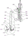
FIG. 1 is a first schematic view of the present invention;
FIG. 2 is a second schematic structural view of the present invention;
fig. 3 is an exploded view of the supporting unit, the adjusting unit and the clamping driving unit of the present invention;
fig. 4 is a schematic view of a part of the structure of the clamping driving unit of the present invention;
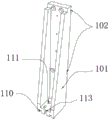
FIG. 5 is a schematic view of the supporting unit structure of the present invention;
FIG. 6 is a schematic view of the wire clamping vise assembly of the present invention;
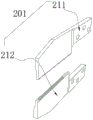
fig. 7 is a schematic structural view of the terminal clamp assembly of the present invention;
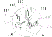
fig. 8 is a schematic view of the structure of the adjusting unit of the present invention.
In the figure: 1. a wire clamping assembly; 2. a clip terminal assembly; 201. a terminal clamp assembly; 211. an upper clamp body; 212. a lower clamp body; 101. a mounting frame; 102. mounting grooves; 103. a U-shaped bracket; 104. a slide rail; 105. a driving cylinder; 151. clamping a connector; 106. a slider; 107. a clamp base; 171. a jaw positioning groove; 172. a clamping groove is linked; 108. lower wire clamps; 109. upper wire clamping pliers; 191. a main handle of the wire clamp; 192. a binding clip; 193. a first fixing bolt; 194. a second fixing bolt; 110. positioning the chute; 111. mounting holes; 112. a first mounting bolt; 113. an adjustment hole; 114. positioning a slide bar; 115. mounting a bolt II; 116. a fixed base; 117. mounting a bolt III; 118. adjusting the bolt; 119. insection rubber pad.
Detailed Description
In the following description, for purposes of explanation, numerous specific details are set forth in order to provide a thorough understanding of the present invention. It should be understood, however, that these physical details should not be taken to limit the invention. That is, in some embodiments of the present invention, such details are not necessary. In addition, for simplicity, some conventional structures and components are shown in the drawings in a simplified schematic manner.
In addition, the descriptions related to "a", "an", "two", etc. in the present invention are only for description purposes, not specifically referring to the order or sequence, and are not intended to limit the present invention, but only to distinguish the components or operations described in the same technical terms, and are not to be construed as indicating or implying any relative importance or implicit indication of the number of technical features indicated. Thus, a feature defined as "a", "an", or "the" may explicitly or implicitly include at least one of the feature. In addition, the technical solutions in the embodiments may be combined with each other, but it must be based on the realization of those skilled in the art, and when the technical solutions are contradictory or cannot be realized, the combination of the technical solutions should not be considered to exist, and is not within the protection scope of the present invention.
Referring to fig. 1, 2 and 3, the present invention provides a wire clamping mechanism for inserting shell, including a wire clamping assembly 1 and a terminal clamping assembly 2, wherein the two assemblies for wire clamping and terminal clamping are separately set up, so that the whole mechanism can adjust two clamping units with different functions according to the production and processing requirements, and compared with the current wire clamping mechanism for inserting shell, the flexibility is higher, and the wire clamping assembly 1 and the terminal clamping assembly 2 include a supporting unit, an adjusting unit and a clamping driving unit; the adjusting unit is positioned on the back of the bottom of the supporting unit so as to conveniently implement micro-distance adjustment on the mounting position of the supporting unit on the terminal shell inserting machine workbench, the clamping driving unit is mounted on the front of the supporting unit, and the clamping driving units in the wire clamping assembly 1 and the clamping terminal assembly 2 are respectively provided with a wire clamping clamp assembly and a terminal clamp assembly 201 so as to independently clamp a flat cable terminal and a wire rod, thereby providing convenience for the subsequent shell inserting operation of the secondary plug-in terminal shell inserting processing technology.
Referring to fig. 1 and 2, the wire clamping assembly 1 and the terminal clamping assembly 2 are arranged at left and right positions, the wire clamping vise assembly and the terminal vise assembly 201 mounted on the clamping driving unit in the wire clamping assembly 1 and the terminal clamping assembly 2 are designed to be opposite, the two clamping assemblies are arranged at left and right positions, and then the relative designs of the wire clamping vise assembly and the terminal vise assembly 201 mounted thereon are combined, so that the independence of the two clamping units in the wire arrangement terminal housing insertion and clamping mechanism can be realized, and sufficient and interference-free operating space can be reserved in the terminal housing insertion processing equipment when the driving mechanism for housing insertion of the wire arrangement terminal is used for performing housing insertion operation subsequently.
The supporting unit is used as a supporting mechanism of the clamping driving unit, the position of the whole independent clamping assembly on the workbench of the terminal machine is realized by matching with the adjusting unit, the purpose of flexibly adjusting the distance between two clamping units in the whole shell inserting and wire clamping mechanism is achieved, and the shell inserting and wire clamping mechanism can be suitable for the conventional secondary shell inserting and processing technology of the flat cable terminal.
Referring to fig. 3 and 5, the supporting unit includes a mounting frame 101, three positioning sliding grooves 110 are formed in the bottom of the mounting frame 101 side by side, a mounting hole 111 is formed in a frame body located between the three positioning sliding grooves 110 at the bottom of the mounting frame 101, and the mounting frame 101 is mounted on a workbench of the terminal machine through the mounting hole 111 in cooperation with a mounting bolt 112.
Referring to fig. 3, 5, and 8, the adjusting unit includes three positioning sliding bars 114 slidably engaged with the positioning sliding grooves 110 and mounted on the working platform of the terminal machine through a second mounting bolt 115, and a fixing base 116 mounted on the working platform of the terminal machine through a third mounting bolt 117; the adjusting unit further comprises an adjusting hole 113 formed in the bottom of the mounting frame 101 and located in the middle of the back face, and an adjusting bolt 118 rotatably clamped on the fixing base 116, the adjusting bolt 118 is in threaded connection with the adjusting hole 113, a plurality of positioning sliding grooves 110 arranged in parallel and a plurality of positioning sliding strips 114 are adopted as positioning mechanisms of the supporting units moving on the terminal inserting shell equipment workbench, the accuracy and the stability of the movement of the supporting units when the positions are adjusted can be improved to the maximum extent, and the wire clamping pliers assemblies and the terminal pliers assemblies 201 can be ensured to be kept unchanged in original directions all the time when the supporting units corresponding to the wire clamping pliers and the terminal pliers are moved.
Referring to fig. 3 and 8, a U-shaped slot is formed in the middle of the top of the fixing base 116, a circle of concave positioning ring is integrally formed on the screw rod of the adjusting bolt 118 near one end of the nut, the adjusting bolt 118 is rotatably clamped to the fixing base 116 by the positioning ring, and the U-shaped slot and the positioning ring are in sliding fit to position the adjusting bolt 118, so that the adjusting bolt 118 can effectively pull or push the supporting unit to move on the positioning slide bar 114 when being screwed in situ.
In order to match with a fixed-point installation hole position on a workbench of the flat cable terminal shell inserting machine and realize the re-fixation of the support unit after the position adjustment, the installation hole 111 is designed into a long-strip-shaped hole groove, and in order to improve the stability of the wire clamping mechanism in the position adjustment process to the maximum extent and keep the directions of the wire clamping clamp assembly and the terminal clamp assembly 201 unchanged, the sizes of the positioning slide bar 114 and the positioning slide groove 110 are mutually matched.
Referring to fig. 3, 4 and 5, the supporting unit further includes mounting grooves 102 formed at the top end and the middle portion of the front surface of the mounting frame 101; the clamping driving unit comprises a slide rail 104 vertically arranged in the middle of the front surface of the mounting frame 101 and U-shaped brackets 103 horizontally arranged in the two mounting grooves 102, the slide rail 104 is positioned between the two U-shaped brackets 103, the slide rail 104 is connected with the two sliding blocks 106 in a sliding manner, and the end parts of the two sliding blocks 106 are provided with linkage clamping grooves 172; two driving cylinders 105 are respectively arranged on the two U-shaped brackets 103 in opposite directions, and the telescopic ends of the two driving cylinders 105 are clamped with a linkage clamping groove 172 on an adjacent sliding block 106 through a clamping joint 151 and form a linkage structure with the sliding block 106; the two sliding blocks 106 are respectively provided with a clamp seat 107 through bolts, and the front surface of the clamp seat 107 is provided with a jaw positioning groove 171 for installing a wire clamping clamp assembly and a terminal clamp assembly 201. The two driving cylinders 105 in the same clamping driving unit adopt synchronous control action, mainly ensuring that two clamp bodies in the wire clamp assembly or the terminal clamp assembly 201 achieve synchronous coordination, and finally realizing clamping of a terminal or a wire rod, and the expansion of the driving cylinders 105 directly realizes linkage fit between the clamping joint 151 and the sliding block 106, and pulling the sliding block 106 to drive the clamp seat 107 to move up and down on the sliding rail 104, and finally achieving the purpose of controlling the wire clamp assembly and the terminal clamp assembly 201 to clamp the corresponding wire rod and the terminal.
Referring to fig. 1 and 2, in order to ensure that the housing-inserting and wire-clamping mechanism can smoothly perform precise position sequential clamping actions on the terminals and wires of the same group of flat cables, and provide corresponding wire secondary clamping and positioning actions for the processing technology of the secondary plug-in housing of the flat cable terminals, the jaws of the terminal clamp assembly 201 and the wire clamp assembly are arranged at the same height position.
Referring to fig. 6, the wire clamping assembly comprises a lower wire clamping jaw 108 and an upper wire clamping jaw 109, the lower wire clamping jaw 108 is designed as an integrated structure, in order to enable the wire clamping assembly to effectively clamp wires with different wire diameters within the moving stroke of a fixed driving cylinder 105 without damaging the wire body on the premise of not replacing the wire clamping assembly, the upper wire clamping jaw 109 is respectively composed of a wire clamping jaw main handle 191, a jaw 192, two first fixing bolts 193 and four second fixing bolts 194; the binding clip 192 is fixed at the bottom of the front end of the main handle 191 of the wire clamp through a first fixing bolt 193, wherein a sliding penetrating structure is arranged between the first fixing bolt 193 and the front end of the main handle 191 of the wire clamp, the end part of the first fixing bolt 193 is screwed in the binding clip 192, four second fixing bolts 194 are respectively positioned at two sides of the two first fixing bolts 193, each second fixing bolt 194 penetrates through the front end of the main handle 191 of the wire clamp and then abuts against the top of the binding clip 192, and the second fixing bolt 194 is in threaded fit with the main handle 191 of the wire clamp; the width of a gap between the plier head 192 and the main handle 191 of the wire clamping plier is controlled by adjusting the number of turns of the first fixing bolt 193 screwed in the plier head 192, so that the width of the gap between the plier head 192 and the main handle 191 of the wire clamping plier is adjusted, the second fixing bolt 194 is arranged to prop against the plier head 192, the first fixing bolt 193 is pulled by the plier head 192 under the action of the main handle 191 of the wire clamping plier, the first fixing bolt 193 can be prevented from automatically falling off from the inside of the plier head 192, the plier head 192 can be positioned at the same time, the opposite sides of the plier head 192 and the front end of the lower wire clamping plier 108 are glued and fixed with the insection rubber pads 119, the insection rubber pads 119 can further improve the protection force of the wire skin, and the wire clamping plier assembly can achieve the maximized wire clamping stabilizing effect under the limited clamping force.
Referring to fig. 7, the terminal clamp assembly 201 is composed of an upper clamp body 211 and a lower clamp body 212, a bayonet for clamping the flat cable terminal is opened on a jaw of the lower clamp body 212, in order to minimize a distance between the terminal clamp assembly 201 and the wire clamping clamp assembly as much as possible, and a flat surface design is adopted on a surface of the upper clamp body 211 and a surface of the lower clamp body 212 close to the wire clamping clamp assembly.
When the distance between the wire clamping caliper assembly and the terminal caliper assembly 201 in the wire clamping assembly 1 and the terminal clamping assembly 2 is adjusted, only the first mounting bolt 112 needs to be loosened (slightly loosened, so that the mounting frame 101 can move on the positioning slide bar 114), according to the actual distance adjustment requirement, the adjusting bolt 118 is screwed according to an applicable tool, the whole supporting unit can be driven to move back and forth along the direction of the positioning slide bar 114 by forward and backward screwing of the screwing bolt, according to the actual requirement, the front and back positions of the whole inserting shell wire clamping mechanism on the workbench of the terminal inserting shell machine can be adjusted, meanwhile, the free adjustment of the distance between two independent clamping units for clamping wires and terminals in the inserting shell wire clamping mechanism can be realized, the whole wire clamping mechanism can be adapted to the inserting shell machining process of the secondary terminals with different wire types, and after the position adjustment is completed, only the first mounting bolt 112 needs to be screwed again, and the supporting unit is fixed.
The above description is only for the embodiment of the present invention, and is not intended to limit the present invention. Various modifications and variations of the present invention will be apparent to those skilled in the art. Any modification, equivalent replacement, or improvement made within the spirit and principle of the present invention should be included in the scope of the claims of the present invention.
Claims (6)
1. The utility model provides a shell inserting wire clamping mechanism which characterized in that: the wire clamping device comprises a wire clamping assembly (1) and a terminal clamping assembly (2), wherein the wire clamping assembly (1) and the terminal clamping assembly (2) respectively comprise a supporting unit, an adjusting unit and a clamping driving unit, the adjusting unit is positioned on the back of the bottom of the supporting unit, the clamping driving unit is installed on the front of the supporting unit, and a wire clamping clamp assembly and a terminal clamp assembly (201) are respectively installed on the clamping driving units in the wire clamping assembly (1) and the terminal clamping assembly (2);
the wire clamping component (1) and the terminal clamping component (2) are arranged at the left and right positions, a wire clamping pliers component and a terminal pliers component (201) which are arranged on a clamping driving unit in the wire clamping component (1) and the terminal clamping component (2) are designed oppositely, and the terminal pliers component (201) is positioned behind the wire clamping pliers component;
the supporting unit comprises a mounting rack (101), three positioning sliding grooves (110) are formed in the bottom of the mounting rack (101) in parallel, a mounting hole (111) is formed in a rack body, which is located between the three positioning sliding grooves (110), in the bottom of the mounting rack (101), and the mounting rack (101) is mounted on a workbench of the terminal machine through the mounting hole (111) in a matching manner with a mounting bolt (112);
the adjusting unit comprises three positioning sliding strips (114) which are in sliding fit with the positioning sliding grooves (110) and are arranged on the working platform of the terminal machine through second mounting bolts (115), and a fixing base (116) which is arranged on the working platform of the terminal machine through third mounting bolts (117); the adjusting unit further comprises an adjusting hole (113) formed in the bottom of the mounting frame (101) and located in the middle of the back face, and an adjusting bolt (118) rotatably clamped on the fixing base (116), wherein the adjusting bolt (118) is in threaded connection with the adjusting hole (113).
2. A housing insertion and wire clamping mechanism according to claim 1, wherein: the clamping groove of U-shaped has been seted up to the intermediate position at fixed baseplate (116) top, adjusting bolt (118) are close to the holding ring of integrated into one piece round indent on the screw rod of nut one end, adjusting bolt (118) realize rotating the joint with fixed baseplate (116) with the help of the holding ring.
3. A housing insertion and wire clamping mechanism according to claim 1, wherein: the mounting hole (111) adopts the design of rectangular shape hole groove, the size of location draw runner (114) and location spout (110) is mutual adaptation.
4. A housing insertion and wire clamping mechanism according to claim 1, wherein: the supporting unit further comprises mounting grooves (102) formed in the top end and the middle of the front face of the mounting frame (101);
the clamping driving unit comprises a sliding rail (104) vertically installed in the middle of the front face of the installation frame (101) and U-shaped brackets (103) horizontally installed in the two installation grooves (102), the sliding rail (104) is located between the two U-shaped brackets (103), the sliding rail (104) is connected with two sliding blocks (106) in a sliding mode, and the end portions of the two sliding blocks (106) are provided with linkage clamping grooves (172); two driving cylinders (105) are respectively arranged on the two U-shaped brackets (103) in opposite directions, and the telescopic ends of the two driving cylinders (105) are clamped with a linkage clamping groove (172) on one adjacent sliding block (106) through clamping joints (151) and form a linkage structure with the sliding block (106);
the two sliding blocks (106) are respectively provided with a clamp seat (107) through a bolt, and the front surface of each clamp seat (107) is provided with a jaw positioning groove (171) for installing a wire clamp assembly and a terminal clamp assembly (201).
5. A housing insertion and wire clamping mechanism according to claim 1, wherein: the wire clamp assembly comprises a lower wire clamp (108) and an upper wire clamp (109), the lower wire clamp (108) is designed into an integrally formed structure, and the upper wire clamp (109) is respectively composed of a wire clamp main handle (191), a clamp head (192), two first fixing bolts (193) and four second fixing bolts (194);
the binding clip (192) is fixed at the bottom of the front end of a main handle (191) of the wire clamp through a first fixing bolt (193), wherein a sliding penetrating structure is arranged between the first fixing bolt (193) and the front end of the main handle (191) of the wire clamp, the end part of the first fixing bolt (193) is screwed in the binding clip (192), four second fixing bolts (194) are respectively positioned at two sides of the two first fixing bolts (193), each second fixing bolt (194) penetrates through the front end of the main handle (191) of the wire clamp and then abuts against the top of the binding clip (192), and the second fixing bolt (194) is in threaded fit with the main handle (191) of the wire clamp;
and a toothed rubber pad (119) is glued and fixed on one side of the clamp head (192) opposite to the front end of the lower wire clamping clamp (108).
6. The shell plugging and wire clamping mechanism of claim 1, wherein: the terminal clamp assembly (201) consists of an upper clamp body (211) and a lower clamp body (212), one surfaces, close to the wire clamping clamp assembly, of the upper clamp body (211) and the lower clamp body (212) adopt a flat surface design, and a clamp opening used for clamping a wire arranging terminal is formed in a clamp opening of the lower clamp body (212);
the jaws of the terminal clamp assembly (201) and the wire clamping clamp assembly are arranged at the same height position.
Priority Applications (1)
| Application Number | Priority Date | Filing Date | Title |
|---|---|---|---|
| CN202223248016.3U CN218648318U (en) | 2022-12-06 | 2022-12-06 | Insert shell wire clamping mechanism |
Applications Claiming Priority (1)
| Application Number | Priority Date | Filing Date | Title |
|---|---|---|---|
| CN202223248016.3U CN218648318U (en) | 2022-12-06 | 2022-12-06 | Insert shell wire clamping mechanism |
Publications (1)
| Publication Number | Publication Date |
|---|---|
| CN218648318U true CN218648318U (en) | 2023-03-17 |
Family
ID=85500959
Family Applications (1)
| Application Number | Title | Priority Date | Filing Date |
|---|---|---|---|
| CN202223248016.3U Active CN218648318U (en) | 2022-12-06 | 2022-12-06 | Insert shell wire clamping mechanism |
Country Status (1)
| Country | Link |
|---|---|
| CN (1) | CN218648318U (en) |
-
2022
- 2022-12-06 CN CN202223248016.3U patent/CN218648318U/en active Active
Similar Documents
| Publication | Publication Date | Title |
|---|---|---|
| US3742571A (en) | Apparatus for trimming and inserting wires | |
| CN103236623B (en) | Threading guide device for double-end crimping | |
| CN216436416U (en) | Wire harness positioning device for low-voltage power distribution cabinet | |
| CN217521225U (en) | Cable harness testing device with high detection efficiency | |
| CN221487050U (en) | Wire rod displacement jumper equipment | |
| CN217019108U (en) | Guide rail welding auxiliary device for power distribution cabinet production | |
| CN112038987B (en) | Bunching arrangement device for computer assembly | |
| CN212209973U (en) | Material moving and assembling mechanism suitable for LED lamp of bent-pin connector | |
| CN210668707U (en) | Contact head connecting device of electrical switch cabinet | |
| CN220138912U (en) | Wire pressing pliers for power engineering | |
| CN215469724U (en) | Machining clamp structure | |
| CN112952524B (en) | Crystal head assembly process and equipment | |
| CN212144012U (en) | Hollow pipe straightening machine | |
| CN218549037U (en) | Automobile connector assembling clamp | |
| CN222448037U (en) | Cable bending jig | |
| CN211182765U (en) | Communication coaxial cable clamping and welding device | |
| CN216389991U (en) | Large-section conductive copper alloy connecting bar crimping device | |
| CN220884288U (en) | Wire harness assembly with reinforced structure | |
| JPH076850A (en) | Wire insertion device | |
| CN224248970U (en) | Alloy moment elastic parallel groove clamp | |
| CN224217884U (en) | Auxiliary tool for data line casing | |
| CN223685989U (en) | Heat shrinkage pipe machine with location structure | |
| CN219535470U (en) | Electric power fast-assembling wire clamp for line transformation | |
| CN223378629U (en) | Wire arrangement device for distribution box | |
| CN220254011U (en) | Cable wiring support |
Legal Events
| Date | Code | Title | Description |
|---|---|---|---|
| GR01 | Patent grant | ||
| GR01 | Patent grant |