CN218640955U - Wheel casing longeron assembly and vehicle - Google Patents
Wheel casing longeron assembly and vehicle Download PDFInfo
- Publication number
- CN218640955U CN218640955U CN202222931592.1U CN202222931592U CN218640955U CN 218640955 U CN218640955 U CN 218640955U CN 202222931592 U CN202222931592 U CN 202222931592U CN 218640955 U CN218640955 U CN 218640955U
- Authority
- CN
- China
- Prior art keywords
- vehicle
- protrusion
- wheel house
- reinforcing
- longitudinal beam
- Prior art date
- Legal status (The legal status is an assumption and is not a legal conclusion. Google has not performed a legal analysis and makes no representation as to the accuracy of the status listed.)
- Active
Links
Images




Landscapes
- Body Structure For Vehicles (AREA)
Abstract
本实用新型公开了一种轮罩纵梁总成和车辆,轮罩纵梁总成包括:纵梁,所述纵梁在车辆的长度方向上延伸;轮罩,所述轮罩设置于所述纵梁的上方且和所述纵梁为一体成型结构,所述轮罩在车辆的宽度方向的内侧设置有加强凸起,所述加强凸起凸出所述轮罩的内表面且在车辆的高度方向上延伸。其中,轮罩和纵梁一体成型,增强轮罩纵梁总成的结构刚度;轮罩上设置有加强凸起,加强凸起可以提高轮罩的扭转刚度,利于纵向力的传递。

The utility model discloses a wheel house longitudinal beam assembly and a vehicle. The wheel house longitudinal beam assembly comprises: a longitudinal beam extending in the longitudinal direction of the vehicle; a wheel housing arranged on the Above the longitudinal beam and integrally formed with the longitudinal beam, the wheel cover is provided with a reinforcing protrusion on the inner side in the width direction of the vehicle, and the reinforcing protrusion protrudes from the inner surface of the wheel housing and is located on the inner surface of the vehicle. extend in the height direction. Among them, the wheel house and the longitudinal beam are integrally formed to enhance the structural rigidity of the wheel house longitudinal beam assembly; the wheel house is provided with reinforcing protrusions, which can improve the torsional rigidity of the wheel house and facilitate the transmission of longitudinal force.
Description
技术领域technical field
本实用新型涉及车辆技术领域,尤其是涉及一种轮罩纵梁总成和车辆。The utility model relates to the technical field of vehicles, in particular to a wheel house longitudinal beam assembly and a vehicle.
背景技术Background technique
后地板总成作为二三排座椅的载体,不仅需要对座椅提供安装点,更重要的是从结构设计上来提升车身后端的舒适性,改善车辆后端的NVH性能,同时加强车辆后端安全系数。As the carrier of the second and third rows of seats, the rear floor assembly not only needs to provide installation points for the seats, but more importantly, from the structural design, it can improve the comfort of the rear end of the vehicle body, improve the NVH performance of the rear end of the vehicle, and at the same time enhance the safety of the rear end of the vehicle coefficient.
相关技术中,车身后地板纵梁和后轮罩内板为单个零部件,两者通过焊接方式进行连接,若两者连接不紧密,在应力传递上可能造成中断,造成应力集中,能量偏高,降低NVH性能。In the related technology, the rear floor longitudinal beam of the vehicle body and the inner panel of the rear wheel house are a single part, and the two are connected by welding. If the connection between the two is not tight, the stress transmission may be interrupted, resulting in stress concentration and high energy , reducing NVH performance.
实用新型内容Utility model content
本实用新型旨在至少解决现有技术中存在的技术问题之一。为此,本实用新型提出了一种轮罩纵梁总成,轮罩和纵梁一体成型,增强轮罩纵梁总成的结构刚度,并且轮罩上设置有加强凸起,加强凸起可以提高轮罩的扭转刚度,利于纵向力的传递。The utility model aims at at least solving one of the technical problems existing in the prior art. For this reason, the utility model proposes a wheel house longitudinal beam assembly, the wheel house and the longitudinal beam are integrally formed to enhance the structural rigidity of the wheel house longitudinal beam assembly, and the wheel house is provided with a reinforcing protrusion, which can Improve the torsional stiffness of the wheel cover, which is conducive to the transmission of longitudinal force.
本实用新型还提出了一种车辆。The utility model also provides a vehicle.
根据本实用新型第一方面实施例的轮罩纵梁总成,包括:纵梁,所述纵梁在车辆的长度方向上延伸;轮罩,所述轮罩设置于所述纵梁的上方且和所述纵梁为一体成型结构,所述轮罩在车辆的宽度方向的内侧设置有加强凸起,所述加强凸起凸出所述轮罩的内表面且在车辆的高度方向上延伸。The wheel house longitudinal beam assembly according to the embodiment of the first aspect of the present utility model includes: a longitudinal beam extending in the longitudinal direction of the vehicle; a wheel housing, the wheel housing being arranged above the longitudinal beam and The wheel cover is integrally formed with the longitudinal beam, and the wheel cover is provided with a reinforcing protrusion on the inner side in the width direction of the vehicle, and the reinforcing protrusion protrudes from the inner surface of the wheel cover and extends in the height direction of the vehicle.
根据本实用新型实施例的轮罩纵梁总成,轮罩和纵梁一体成型,增强轮罩纵梁总成的结构刚度;轮罩上设置有加强凸起,加强凸起可以提高轮罩的扭转刚度,利于纵向力的传递。According to the wheel house longitudinal beam assembly of the embodiment of the utility model, the wheel house and the longitudinal beam are integrally formed to enhance the structural rigidity of the wheel house longitudinal beam assembly; Torsional rigidity is conducive to the transmission of longitudinal force.
根据本实用新型的一些实施例,所述加强凸起包括:第一凸起和第二凸起,所述第一凸起设置于所述第二凸起的上方;以及,在车辆的长度方向上,所述第一凸起朝向所述第二凸起的一端的尺寸小于所述第一凸起背离所述第二凸起的一端的尺寸;和/或,所述第二凸起朝向所述第一凸起的一端的尺寸小于所述第二凸起背离所述第一凸起的一端的尺寸。According to some embodiments of the present utility model, the reinforcing protrusion includes: a first protrusion and a second protrusion, the first protrusion is disposed above the second protrusion; and, in the longitudinal direction of the vehicle Above, the size of the end of the first protrusion facing the second protrusion is smaller than the size of the end of the first protrusion facing away from the second protrusion; and/or, the second protrusion faces the The dimension of one end of the first protrusion is smaller than the dimension of the end of the second protrusion away from the first protrusion.
根据本实用新型的一些实施例,所述加强凸起在车辆的长度方向的一侧与车辆的长度方向之间的夹角为α1,所述加强凸起在车辆的长度方向的另一侧与车辆的长度方向之间的夹角为α2,α1和α2满足关系式:|α1-α2|>10°。According to some embodiments of the present utility model, the included angle between the reinforcing protrusion on one side of the longitudinal direction of the vehicle and the longitudinal direction of the vehicle is α1, and the reinforcing protrusion is connected to the other side of the longitudinal direction of the vehicle. The included angle between the longitudinal directions of the vehicle is α2, and α1 and α2 satisfy the relational expression: |α1−α2|>10°.
根据本实用新型的一些实施例,所述轮罩在车辆的宽度方向的内侧和/或外侧设置第一加强筋,所述第一加强筋在车辆的高度方向上延伸,所述第一加强筋设置于所述加强凸起的至少一侧。According to some embodiments of the present utility model, the wheel cover is provided with a first reinforcing rib on the inner side and/or outer side in the width direction of the vehicle, the first reinforcing rib extends in the height direction of the vehicle, and the first reinforcing rib It is arranged on at least one side of the reinforcing protrusion.
根据本实用新型的一些实施例,所述轮罩上设置有第一平面和第二平面,所述第一平面和所述第二平面分别设置在所述加强凸起在车辆的长度方向的前侧和后侧,所述第一平面和所述第二平面的数量不同和/或面积不同。According to some embodiments of the present utility model, a first plane and a second plane are arranged on the wheel cover, and the first plane and the second plane are respectively arranged in front of the reinforcing protrusion in the longitudinal direction of the vehicle. The number and/or area of the first plane and the second plane are different on the side and the rear side.
根据本实用新型的一些实施例,所述纵梁在车辆的宽度方向的外侧设置有安装翻边,所述安装翻边在车辆的宽度方向桑的一侧以及在车辆高度方向上的一侧均与门槛梁固定连接。According to some embodiments of the present invention, the longitudinal beam is provided with a mounting flange on the outer side in the width direction of the vehicle, and the mounting flange is located on one side in the width direction of the vehicle and on one side in the vehicle height direction. Fixed connection with sill beam.
根据本实用新型的一些实施例,所述纵梁在车辆的宽度方向的内侧设置有第二加强筋,所述第二加强筋在车辆的长度方向和高度方向上延伸,所述第二加强筋和所述安装翻边对应。According to some embodiments of the present utility model, the side beam is provided with a second reinforcing rib on the inner side of the width direction of the vehicle, the second reinforcing rib extends in the length direction and the height direction of the vehicle, and the second reinforcing rib Corresponding to the installation flange.
根据本实用新型的一些实施例,所述纵梁在车辆的高度方向的下方设置有多个安装部,所述安装部用于安装后副车架和减震器;以及,所述纵梁在车辆的宽度方向的内侧设置有第三加强筋,所述第三加强筋和所述安装部对应。According to some embodiments of the present utility model, the longitudinal beam is provided with a plurality of installation parts below the height direction of the vehicle, and the installation parts are used to install the rear sub-frame and the shock absorber; A third reinforcing rib is provided on the inner side in the width direction of the vehicle, and the third reinforcing rib corresponds to the mounting portion.
根据本实用新型的一些实施例,所述轮罩纵梁总成还包括:多个第四加强筋,所述第四加强筋设置在所述纵梁和所述轮罩的连接处,多个所述第四加强筋在车辆的长度方向间隔设置。According to some embodiments of the present utility model, the wheel house longitudinal beam assembly further includes: a plurality of fourth reinforcing ribs, the fourth reinforcing ribs are arranged at the connection between the longitudinal beam and the wheel house, and a plurality of The fourth reinforcing ribs are arranged at intervals in the longitudinal direction of the vehicle.
根据本实用新型第二方面实施例的车辆,包括:所述轮罩纵梁总成。The vehicle according to the embodiment of the second aspect of the utility model includes: the wheel house side member assembly.
本实用新型的附加方面和优点将在下面的描述中部分给出,部分将从下面的描述中变得明显,或通过本实用新型的实践了解到。Additional aspects and advantages of the invention will be set forth in the description which follows, and in part will be obvious from the description, or may be learned by practice of the invention.
附图说明Description of drawings
本实用新型的上述和/或附加的方面和优点从结合下面附图对实施例的描述中将变得明显和容易理解,其中:The above and/or additional aspects and advantages of the present utility model will become apparent and easy to understand from the description of the embodiments in conjunction with the following drawings, wherein:
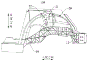
图1是根据本实用新型实施例的轮罩纵梁总成的一个方向的示意图;Fig. 1 is a schematic diagram of one direction of a wheel house longitudinal beam assembly according to an embodiment of the present invention;
图2是根据本实用新型实施例的轮罩纵梁总成的另一个方向的示意图;Fig. 2 is a schematic diagram of another direction of the wheel house longitudinal beam assembly according to the embodiment of the present invention;
图3是根据本实用新型实施例的轮罩纵梁总成的又一个方向的示意图;Fig. 3 is a schematic diagram of another direction of the wheel house longitudinal beam assembly according to the embodiment of the present invention;
图4是根据本实用新型实施例的轮罩的剖面图;Fig. 4 is a sectional view of a wheel cover according to an embodiment of the present invention;
图5是根据本实用新型实施例的轮罩纵梁总成的局部示意图;Fig. 5 is a partial schematic view of the wheel house longitudinal beam assembly according to the embodiment of the present invention;
图6是根据本实用新型实施例的轮罩纵梁总成的侧视图;Fig. 6 is a side view of the wheel house longitudinal beam assembly according to the embodiment of the present invention;
图7是根据本实用新型实施例的轮罩纵梁总成的再一个方向的示意图。Fig. 7 is a schematic diagram of another direction of the wheel house longitudinal beam assembly according to the embodiment of the present invention.
附图标记:Reference signs:
100、轮罩纵梁总成;100. Wheel house longitudinal beam assembly;
10、纵梁;11、安装翻边;12、第二加强筋;13、安装部;14、第三加强筋;10. Longitudinal beam; 11. Installation flanging; 12. Second rib; 13. Installation part; 14. Third rib;
20、轮罩;21、加强凸起;211、第一凸起;212、第二凸起;22、第一加强筋;23、第一平面;24、第二平面;20. Wheel cover; 21. Reinforced protrusion; 211. First protrusion; 212. Second protrusion; 22. First rib; 23. First plane; 24. Second plane;
30、第四加强筋。30. The fourth rib.
具体实施方式Detailed ways
下面详细描述本实用新型的实施例,参考附图描述的实施例是示例性的,下面详细描述本实用新型的实施例。Embodiments of the utility model are described in detail below, and the embodiments described with reference to the accompanying drawings are exemplary, and embodiments of the utility model are described in detail below.
下面参考图1-图7描述根据本实用新型实施例的轮罩纵梁总成100,本实用新型还提出了一种具有上述轮罩纵梁总成100的车辆。The following describes a wheel house
结合图1-图2所示,轮罩纵梁总成100包括:纵梁10和轮罩20,纵梁10在车辆的长度方向上延伸;轮罩20设置于纵梁10的上方且和纵梁10为一体成型结构。具体地,纵梁10在车辆的长度方向上延伸,在车辆的高度方向上,轮罩20和纵梁10呈拱形,能极大提高应力的传输效率,优化应力传递,避免应力集中,同时具有更高的支撑效果。1-2, the wheel house
轮罩20位于纵梁10的上方,并且纵梁10和轮罩20为一体成型结构,可增强轮罩纵梁总成100的结构刚度、强度,一体成型的轮罩纵梁总成100的加工工序少,无需单独装配连接,生产成本较低,使得轮罩纵梁总成100具有良好的力学性能,同时节省制造费用。其中,轮罩纵梁总成100为铝合金件,铝合金件的质量轻,便于加工、安装。The
以及,轮罩20在车辆的宽度方向的内侧设置有加强凸起21,加强凸起21凸出轮罩20的内表面且在车辆的高度方向上延伸。也就是说,在车辆的宽度方向上,轮罩20的内侧设置有加强凸起21,加强凸起21在轮罩20上朝向车身方向凸起,加强凸起21凸出于轮罩20的内表面,并且加强凸起21在车辆的高度方向上延伸,极大提高了轮罩20的扭转刚度,同时也利于纵向力的传递。And, the
由此,轮罩20和纵梁10一体成型,增强轮罩纵梁总成100的结构刚度,并且轮罩20上设置有加强凸起21,加强凸起21可以提高轮罩20的扭转刚度,利于纵向力的传递。Thus, the
如图2所示,加强凸起21包括:第一凸起211和第二凸起212,第一凸起211设置于第二凸起212的上方,以及,在车辆的长度方向上,第一凸起211朝向第二凸起212的一端的尺寸小于第一凸起211背离第二凸起212的一端的尺寸。具体地,加强凸起21上包括有第一凸起211和第二凸起212,在车辆的高度方向上,第一凸起211位于第二凸起212的上方,在车辆的长度方向上,第一凸起211朝向第二凸起212的一端的尺寸小于第一凸起211背离第二凸起212的一端的尺寸,即,第一凸起211从下往上在长度方向上的截面尺寸越来越大,保证轮罩20的结构强度。As shown in Figure 2, the reinforcing
又或者,第二凸起212朝向第一凸起211的一端的尺寸小于第二凸起212背离第一凸起211的一端的尺寸。具体地,第二凸起212位于第一凸起211的下方,第二凸起212朝向第一凸起211的一端的尺寸小于第二凸起212背离第一凸起211的一端的尺寸,即,第二凸起212从上往下在长度方向上的截面尺寸越来越大,保证轮罩纵梁总成100的结构刚度。Alternatively, the size of the end of the
由此,在车辆的高度方向上,加强凸起21的形状从上往下呈现为先收拢,后发散,更好的对轮罩20起到支撑作用,便于纵向力的传递。Therefore, in the height direction of the vehicle, the shape of the reinforcing
根据图5所示,加强凸起21在车辆的长度方向的一侧与车辆的长度方向之间的夹角为α1,加强凸起21在车辆的长度方向的另一侧与车辆的长度方向之间的夹角为α2,α1和α2满足关系式:|α1-α2|>10°。具体地,在车辆的长度方向上,加强凸起21的其中一侧与与车辆的长度方向的夹角为α1,加强凸起21的另一侧与车辆的长度方向之间的夹角为α2,α1和α2角度的差值大于10°,保证加强凸起21在车辆长度方向上的两侧的倾斜角度不同,可以衰减此处的振动能量,降低振动灵敏度,提高轮罩纵梁总成100的结构多样性,避免产生共振。优选地,α1的角度为85.7°,α2的角度为73.2°。As shown in FIG. 5 , the angle between the reinforcing
如图2和图3所示,轮罩20在车辆的宽度方向的内侧和/或外侧设置第一加强筋22,第一加强筋22在车辆的高度方向上延伸,第一加强筋22设置于加强凸起21的至少一侧。具体地,在车辆的宽度方向上,轮罩20的内侧设置有第一加强筋22,轮罩20的外侧也设置有第一加强筋22,第一加强筋22在车辆的高度方向上延伸,第一加强筋22位于加强凸起21的一侧或者两侧,提高轮罩20的弯扭刚度,同时也利于纵向力的传递。As shown in Figures 2 and 3, the
结合图2所示,轮罩20上设置有第一平面23和第二平面24,第一平面23和第二平面24分别设置在加强凸起21在车辆的长度方向的前侧和后侧,第一平面23和第二平面24的数量不同和/或面积不同。具体地,轮罩20上包括有第一平面23和第二平面24,在车辆的长度方向上,第一平面23和第二平面24分别位于加强凸起21的前后两侧,第一平面23与第二平面24的数量不同,又或者第一平面23与第二平面24的面积不同,差异化的面积设计能避免轮罩20的前后部共振,降低路噪辐射,改善车内噪声水平。2, the
具体地,第一平面23与第二平面24的总面积比大致为2:1。Specifically, the total area ratio of the
以及,在车辆的长度方向的前侧和后侧还设置有弧面,其中,弧面设置在第一平面23和第二平面24在车辆的宽度方向的外侧。具体地,加强凸起21的前部和后部分别设置有一个弧面,其中,弧面有利于避让车轮。And, arc surfaces are further provided on the front and rear sides in the longitudinal direction of the vehicle, wherein the arc surfaces are provided on the outer sides of the
另外,在轮罩20上设置第一平面23与第二平面24,有利于轮罩饰板的安装。In addition, the
如图2和图5所示,纵梁10在车辆的宽度方向的外侧设置有安装翻边11,安装翻边11在车辆的宽度方向的一侧以及在车辆的高度方向的一侧均与门槛梁固定连接。具体地,在车辆的宽度方向上,纵梁10的外侧设置有安装翻边11,安装翻边11位于纵梁10朝向车身前侧的一端。在车辆的宽度方向上,安装翻边11背离纵梁10的一侧与门槛梁相配合,使得纵梁10与门槛梁相连接固定,以及,在车辆的高度方向上,安装翻边11的上侧与门槛梁固定连接,同样使得纵梁10与门槛梁相连接固定。如此,通过安装翻边11可以实现纵梁10与门槛梁之间的连接。其中,安装翻边11为直角翻边。As shown in Figures 2 and 5, the
如图3、图6和图7所示,纵梁10在车辆的宽度方向的内侧设置有第二加强筋12,第二加强筋12在车辆的长度方向和高度方向上延伸,第二加强筋12和安装翻边11对应。具体地,在车辆的宽度方向上,纵梁10上设置有第二加强筋12,第二加强筋12为多个,多个第二加强筋12在车辆的长度方向上和高度方向上延伸,第二加强筋12与安装翻边11相对应,第二加强筋12之间构成多个矩形空腔,一方面能大幅提高纵梁10的刚度和模态,提升强度,另一方面是矩形空腔具有极大缓冲吸能作用,提高安全性。As shown in Fig. 3, Fig. 6 and Fig. 7, the
结合图6所示,纵梁10在车辆的高度方向的下方设置有多个安装部13,安装部13用于安装后副车架和减震器,以及,纵梁10在车辆的宽度方向的内侧设置有第三加强筋14,第三加强筋14和安装部13对应。具体地,在车辆的高度方向上,纵梁10上设置有多个安装部13,安装部13可以用于安装后副车架和减震器;在车辆的宽度方向上,纵梁10的内侧设置有多个第三加强筋14,多个第三加强筋14和安装部13相对应,也就是说在安装部13设置多个第三加强筋14,多个第三加强筋14分别构成三角形空腔,三角形空腔可以提高安装部13的动刚度,衰减激励,降低能量的传递。6, the
进一步地,轮罩纵梁总成100还包括:多个第四加强筋30,第四加强筋30设置在纵梁10和轮罩20的连接处,多个第四加强筋30在车辆的长度方向间隔设置。具体地,轮罩纵梁总成100上还设置有多个第四加强筋30,第四加强筋30位于纵梁10和轮罩20的连接处,多个第四加强筋30相互间隔,多个第四加强筋30在车辆的高度方向上延伸,对纵梁10起到一定的支撑作用,第四加强筋30加强了纵梁10与轮罩20的连接强度,提高了轮罩纵梁总成100的整体刚度。Further, the wheel house
根据本实用新型第二方面实施例的车辆,包括:轮罩纵梁总成100。在本实用新型的描述中,需要理解的是,术语“中心”、“纵向”、“横向”、“长度”、“宽度”、“厚度”、“上”、“下”、“前”、“后”、“左”、“右”、“竖直”、“水平”、“顶”、“底”、“内”、“外”、“顺时针”、“逆时针”、“轴向”、“径向”、“周向”等指示的方位或位置关系为基于附图所示的方位或位置关系,仅是为了便于描述本实用新型和简化描述,而不是指示或暗示所指的装置或元件必须具有特定的方位、以特定的方位构造和操作,因此不能理解为对本实用新型的限制。The vehicle according to the embodiment of the second aspect of the utility model includes: a wheel house
在本说明书的描述中,参考术语“一个实施例”、“一些实施例”、“示意性实施例”、“示例”、“具体示例”、或“一些示例”等的描述意指结合该实施例或示例描述的具体特征、结构、材料或者特点包含于本实用新型的至少一个实施例或示例中。在本说明书中,对上述术语的示意性表述不一定指的是相同的实施例或示例。In the description of this specification, references to the terms "one embodiment," "some embodiments," "exemplary embodiments," "example," "specific examples," or "some examples" are intended to mean that the implementation Specific features, structures, materials or characteristics described in an embodiment or example are included in at least one embodiment or example of the present invention. In this specification, schematic representations of the above terms do not necessarily refer to the same embodiment or example.
尽管已经示出和描述了本实用新型的实施例,本领域的普通技术人员可以理解:在不脱离本实用新型的原理和宗旨的情况下可以对这些实施例进行多种变化、修改、替换和变型,本实用新型的范围由权利要求及其等同物限定。Although the embodiments of the present invention have been shown and described, those skilled in the art can understand that various changes, modifications, substitutions and modifications, the scope of the present invention is defined by the claims and their equivalents.
Claims (10)
Priority Applications (1)
| Application Number | Priority Date | Filing Date | Title |
|---|---|---|---|
| CN202222931592.1U CN218640955U (en) | 2022-11-03 | 2022-11-03 | Wheel casing longeron assembly and vehicle |
Applications Claiming Priority (1)
| Application Number | Priority Date | Filing Date | Title |
|---|---|---|---|
| CN202222931592.1U CN218640955U (en) | 2022-11-03 | 2022-11-03 | Wheel casing longeron assembly and vehicle |
Publications (1)
| Publication Number | Publication Date |
|---|---|
| CN218640955U true CN218640955U (en) | 2023-03-17 |
Family
ID=85495994
Family Applications (1)
| Application Number | Title | Priority Date | Filing Date |
|---|---|---|---|
| CN202222931592.1U Active CN218640955U (en) | 2022-11-03 | 2022-11-03 | Wheel casing longeron assembly and vehicle |
Country Status (1)
| Country | Link |
|---|---|
| CN (1) | CN218640955U (en) |
-
2022
- 2022-11-03 CN CN202222931592.1U patent/CN218640955U/en active Active
Similar Documents
| Publication | Publication Date | Title |
|---|---|---|
| CN209037663U (en) | The full frame subframe of one and vehicle | |
| CN116161119A (en) | Aluminum auxiliary frame of electric car | |
| CN219277628U (en) | Vehicle reinforcement beams, nacelle assemblies and vehicles | |
| CN110626432B (en) | Vehicle body structure and vehicle | |
| CN223355523U (en) | Front cabin connecting structure and vehicle | |
| CN209466944U (en) | A high-rigidity lightweight magnesium alloy shock absorber support and its connection structure | |
| CN218316130U (en) | Shock towers and vehicles | |
| CN218400711U (en) | Connection structure and vehicle of sub vehicle frame and automobile body | |
| CN215205073U (en) | A suspension installation assembly, floor assembly and automobile | |
| CN214451356U (en) | Reinforcing support and vehicle body | |
| CN221393705U (en) | Vehicle body reinforcing ring assembly, vehicle body and vehicle | |
| CN219115560U (en) | Frame assembly and vehicle | |
| CN217396653U (en) | Shock absorber seat assembly of vehicle and vehicle that has it | |
| CN221292960U (en) | Powertrain suspension installation assembly and vehicle | |
| CN219446697U (en) | Door reinforcement, door assembly and vehicle | |
| CN220390960U (en) | Suspension mounting structure and vehicle | |
| CN219447147U (en) | Middle floor assembly, floor assembly and vehicle | |
| CN218431411U (en) | Frame assembly and vehicle | |
| CN218806106U (en) | Subframe and vehicle | |
| CN217945324U (en) | Vehicle body suspension mounting structure, vehicle body longitudinal beam assembly and vehicle | |
| CN223199858U (en) | Suspension arrangement system and vehicle | |
| CN218640949U (en) | Cabin longitudinal beam of vehicle and vehicle | |
| CN218640948U (en) | Cabin longeron assembly and vehicle | |
| CN223072579U (en) | Roof cross beam assembly of vehicle and vehicle | |
| CN115284806B (en) | Swing arm mounting assembly and vehicle |
Legal Events
| Date | Code | Title | Description |
|---|---|---|---|
| GR01 | Patent grant | ||
| GR01 | Patent grant |