CN218634472U - Intelligent digital controller of electric power rectifier cabinet - Google Patents
Intelligent digital controller of electric power rectifier cabinet Download PDFInfo
- Publication number
- CN218634472U CN218634472U CN202222215947.7U CN202222215947U CN218634472U CN 218634472 U CN218634472 U CN 218634472U CN 202222215947 U CN202222215947 U CN 202222215947U CN 218634472 U CN218634472 U CN 218634472U
- Authority
- CN
- China
- Prior art keywords
- framework
- montant
- controller body
- power rectifier
- controller
- Prior art date
- Legal status (The legal status is an assumption and is not a legal conclusion. Google has not performed a legal analysis and makes no representation as to the accuracy of the status listed.)
- Active
Links
- 230000000694 effects Effects 0.000 claims abstract description 21
- 238000000034 method Methods 0.000 description 6
- 238000005457 optimization Methods 0.000 description 5
- 230000009471 action Effects 0.000 description 3
- 230000008569 process Effects 0.000 description 3
- 230000008859 change Effects 0.000 description 2
- 238000001125 extrusion Methods 0.000 description 2
- 230000004075 alteration Effects 0.000 description 1
- 230000009286 beneficial effect Effects 0.000 description 1
- 230000008901 benefit Effects 0.000 description 1
- 238000010586 diagram Methods 0.000 description 1
- 238000012986 modification Methods 0.000 description 1
- 230000004048 modification Effects 0.000 description 1
- 238000006467 substitution reaction Methods 0.000 description 1
Images


Landscapes
- Patch Boards (AREA)
Abstract
The utility model belongs to the technical field of rectifier cabinet controller, and an electric power rectifier cabinet intelligence digital controller is disclosed, the controller comprises a controller body, the fixed framework that has cup jointed of surface of controller body front end, the cover piece has been cup jointed in the inside activity on framework top, the inside of cup jointing both ends about the piece all fixed cover has been cup jointed the montant. The utility model discloses a set up the handle, montant and stiff spring, through upwards pulling the handle, thereby will drive the montant through the cup jointing piece and take place rebound and tensile stiff spring along the inner wall of controller body, and then the lower extreme that will drive the montant breaks away from the inside of the whole cabinet mounting hole of electric power, thereby the fixed effect to the controller body has been removed, then through outwards pulling the handle, thereby will make the frame drive controller body break away from the electric power rectifier cabinet mounting groove, and then reached the purpose of the controller body convenient to dismantle fast.
Description
Technical Field
The utility model belongs to the technical field of the rectifier cabinet controller, specifically electric power rectifier cabinet intelligence digital control ware.
Background
At present, electric power rectifier cabinet is in the use, often need use intelligent digital control ware, and intelligent digital control ware among the prior art is at the in-process of in-service use, though can reach basically through starting the purpose that electric power rectifier cabinet carries out the rectification to electric power, but because it lacks the structure of good quick dismantlement of being convenient for, thereby lead to operating personnel can not be quick when intelligent digital control ware damages to dismantle the change, and then make the quick timely work that carries on of electric power rectifier cabinet, consequently need improve it.
SUMMERY OF THE UTILITY MODEL
The utility model aims at the above problem, the utility model provides an electric power rectifier cabinet intelligence digital control ware has the advantage of being convenient for dismantle fast.
In order to achieve the above object, the utility model provides a following technical scheme: electric power rectifier cabinet intelligence digital controller, including the controller body, the fixed surface cover of controller body front end has cup jointed the framework, the internal movement on framework top has cup jointed the piece, the inside at both ends is all cup jointed the montant about the piece, the lower extreme of montant runs through the framework and extends to the outside of framework and cup joints with the inner wall activity of framework, the inside of framework has been seted up and has been located the left dead slot of montant, the bottom fixed mounting of cup jointing the piece has the rigid spring who is located the dead slot inside, rigid spring's the other end and the inner wall fixed connection of dead slot, the top fixed mounting of cup jointing the piece has the handle of montant front side.
As the utility model discloses preferred, the inside fixed mounting of framework has the dead lever that is located controller body front side, the dog has been cup jointed in the surface activity of dead lever, the surface of dog is cup jointed with the inner wall activity of framework.
As the utility model discloses it is preferred, the cavity has been seted up to the inside of dog, the movable block has been cup jointed in the inside activity of cavity.
As the utility model discloses preferred, the bottom fixed mounting of movable block has flexible spring, flexible spring's the other end and the inner wall fixed connection of cavity.
As the utility model discloses it is preferred, the draw-in groove has been seted up to the inside of framework, the card pole has been cup jointed in the inside activity of draw-in groove, the lower extreme of card pole runs through dog and movable block in proper order and cup joints with the inner wall activity of dog and cup joints with the inner wall of movable block is fixed cup joints.
As the utility model discloses it is preferred, the side mouth that is located the movable block right side is seted up to the inside of dog, the pull rod has been cup jointed in the inside activity of side mouth, the left end and the movable block fixed connection of pull rod, the right-hand member of pull rod is located the outside of dog.
Compared with the prior art, the beneficial effects of the utility model are as follows:
1. the utility model discloses a set up the handle, montant and stiff spring, through upwards pulling the handle, thereby will drive the montant through the cup jointing piece and take place rebound and tensile stiff spring along the inner wall of controller body, and then the lower extreme that will drive the montant breaks away from the inside of the whole cabinet mounting hole of electric power, thereby the fixed effect to the controller body has been removed, then through outwards pulling the handle, thereby will make the frame drive controller body break away from the electric power rectifier cabinet mounting groove, and then reached the purpose of the controller body convenient to dismantle fast.
2. The utility model discloses a set up the dead lever, dog and kelly, through the mutually supporting between dead lever and the dog, thereby will make the dog take place to rotate as the axle center with the dead lever and keep off the controller body, then through the design of flexible spring, thereby will reset flexible spring extrusion movable block and kelly, and then will make the kelly remove to the inside of draw-in groove wholly fixed the dog, so design, alright controller body can't touch controller body display screen or button messenger display screen or button damage when using external article, and then reached the purpose that blocks the protection control body.
Drawings
FIG. 1 is a schematic structural view of the present invention;
FIG. 2 is a schematic diagram of the controller body structure of the present invention;
FIG. 3 is a front cross-sectional structural view of the stopper of the present invention;
fig. 4 is a schematic side sectional structure view of the utility model of the montant;
FIG. 5 is a schematic side sectional view of the present invention;
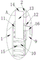
fig. 6 is a schematic view of a part a of the enlarged structure in fig. 5.
In the figure: 1. a controller body; 2. a frame body; 3. sleeving and connecting blocks; 4. a handle; 5. a vertical rod; 6. an empty groove; 7. a rigid spring; 8. fixing the rod; 9. a stopper; 10. a cavity; 11. a moving block; 12. a side port; 13. a clamping rod; 14. a card slot; 15. a flexible spring; 16. a pull rod.
Detailed Description
The technical solutions in the embodiments of the present invention will be described clearly and completely with reference to the accompanying drawings in the embodiments of the present invention, and it is obvious that the described embodiments are only some embodiments of the present invention, not all embodiments. Based on the embodiments in the present invention, all other embodiments obtained by a person skilled in the art without creative work belong to the protection scope of the present invention.
As shown in fig. 1 to 6, the utility model provides an electric power rectifier cabinet intelligence digital controller, including controller body 1, the fixed cover of surface of 1 front end of controller body has connect framework 2, the inside activity on framework 2 top has cup jointed piece 3, the inside of cup jointing piece 3 left and right sides both ends has all cup jointed montant 5, the lower extreme of montant 5 runs through framework 2 and extends to framework 2's outside and cup joints with framework 2's inner wall activity, framework 2's inside has been seted up and has been located the left dead slot 6 of montant 5, the bottom fixed mounting who cup joints piece 3 has the rigid spring 7 that is located dead slot 6 inside, the other end of rigid spring 7 and the inner wall fixed connection of dead slot 6, the top fixed mounting who cup joints piece 3 has handle 4 of the 5 front sides of montant.
This design definition framework 2 is outside for electric power rectifier cabinet mounting groove, the rear end of controller body 1 cup joints for the inner wall activity of electric power rectifier cabinet mounting groove is inside and with the electric power rectifier cabinet mounting groove, the lower extreme of montant 5 is the inside of electric power rectifier cabinet mounting hole simultaneously, when needs are dismantled controller body 1, operating personnel is through upwards pulling handle 4 this moment, thereby will drive montant 5 through cup jointing piece 3 and take place the rebound along the inner wall of controller body 1, and then will make the tensile rigid spring 7 of cup jointing piece 3, and drive the lower extreme of montant 5 and break away from the inside of the whole cabinet mounting hole of electric power, and then remove the fixed effect to controller body 1, then operating personnel alright outwards pulls handle 4, thereby will make framework 2 drive controller body 1 break away from the electric power rectifier cabinet mounting groove, and then reached the purpose of controller body 1 of being convenient for quick dismantlement.
Referring to fig. 3, a fixing rod 8 located at the front side of the controller body 1 is fixedly installed inside the frame body 2, a stopper 9 is movably sleeved on the outer surface of the fixing rod 8, and the outer surface of the stopper 9 is movably sleeved on the inner wall of the frame body 2.
As a technical optimization scheme of the utility model, through the design of dead lever 8 to will make dog 9 use dead lever 8 to take place to rotate and keep off controller body 1 as the axle center.
Referring to fig. 6, a cavity 10 is formed inside the stopper 9, and a moving block 11 is movably sleeved inside the cavity 10.
As a technical optimization scheme of the present invention, the inner wall of the cavity 10 and the outer surface of the moving block 11 are smooth, so that the moving block 11 is smoother in the process of movement.
Referring to fig. 6, a flexible spring 15 is fixedly mounted at the bottom of the moving block 11, and the other end of the flexible spring 15 is fixedly connected with the inner wall of the cavity 10.
As a technical optimization scheme of the utility model, through the design of flexible spring 15 to will make movable block 11 have good elasticity reset function.
Referring to fig. 6, a clamping groove 14 is formed in the frame 2, a clamping rod 13 is movably sleeved in the clamping groove 14, and a lower end of the clamping rod 13 sequentially penetrates through the stop block 9 and the moving block 11, is movably sleeved on an inner wall of the stop block 9, and is fixedly sleeved on an inner wall of the moving block 11.
As a technical optimization scheme of the utility model, through mutually supporting between kelly 13 and draw-in groove 14 to will make kelly 13 fix dog 9 is whole through draw-in groove 14.
Referring to fig. 6, a side opening 12 located on the right side of the moving block 11 is formed in the stopper 9, a pull rod 16 is movably sleeved in the side opening 12, the left end of the pull rod 16 is fixedly connected with the moving block 11, and the right end of the pull rod 16 is located outside the stopper 9.
As a technical optimization scheme of the utility model, through pulling pull rod 16 to will drive movable block 11 and take place to remove and compress flexible spring 15 along the inner wall of cavity 10, and then will drive kelly 13 and break away from the inside of draw-in groove 14, thereby has removed the holistic fixed effect to dog 9.
The utility model discloses a theory of operation and use flow:
when needs are dismantled controller body 1, operating personnel is through upwards pulling handle 4 this moment, thereby will drive montant 5 through splicing block 3 and take place the rebound along the inner wall of controller body 1, and then will drive the inside that the lower extreme of montant 5 breaks away from the whole cabinet mounting hole of electric power, thereby will make splicing block 3 tensile rigid spring 7, and then has removed the fixed effect to controller body 1, then operating personnel alright outwards stimulate handle 4, thereby will make framework 2 drive controller body 1 break away from the electric power rectifier cabinet mounting groove, and then reached the purpose of the controller body 1 of being convenient for dismantle fast, thereby will make operating personnel can change controller body 1 fast.
When not using controller body 1, operating personnel is through pulling pull rod 16 this moment, thereby will drive movable block 11 and take place to remove and compress flexible spring 15 along the inner wall of cavity 10, and then will drive the inside that the upper end of kelly 13 removed to dog 9, then operating personnel is through using dead lever 8 to rotate as the axle center and block controller body 1 with dog 9, operating personnel is through loosening pull rod 16 afterwards, thereby will flexible spring 15 extrusion movable block 11 and kelly 13 reset, and then will make kelly 13 remove to the inside of draw-in groove 14, thereby reached the holistic fixed effect to dog 9, so on this design, alright make controller body 1 unable touch controller body 1 display screen or button when using and make display screen or button damage, and then reached the purpose that blocks protection controller body 1.
It should be noted that, in this document, relational terms such as first and second, and the like are used solely to distinguish one entity or action from another entity or action without necessarily requiring or implying any actual such relationship or order between such entities or actions. Also, the terms "comprises," "comprising," or any other variation thereof, are intended to cover a non-exclusive inclusion, such that a process, method, article, or apparatus that comprises a list of elements does not include only those elements but may include other elements not expressly listed or inherent to such process, method, article, or apparatus.
Although embodiments of the present invention have been shown and described, it will be appreciated by those skilled in the art that various changes, modifications, substitutions and alterations can be made in these embodiments without departing from the principles and spirit of the invention, the scope of which is defined in the appended claims and their equivalents.
Claims (6)
1. Electric power rectifier cabinet intelligence digital control ware, including controller body (1), its characterized in that: the fixed cover of surface of controller body (1) front end has connect framework (2), the inside activity on framework (2) top has cup jointed piece (3), the inside of both ends is all cup jointed montant (5) about cup jointed piece (3), the lower extreme of montant (5) runs through framework (2) and extends to the outside of framework (2) and cup joints with the inner wall activity of framework (2), the inside of framework (2) is seted up and is located montant (5) left dead slot (6), the bottom fixed mounting of cup jointing piece (3) has rigid spring (7) that are located dead slot (6) inside, the other end of rigid spring (7) and the inner wall fixed connection of dead slot (6), the top fixed mounting of cup jointing piece (3) has handle (4) of montant (5) front side.
2. The intelligent digital controller for the power rectifier cabinet according to claim 1, wherein: the inside fixed mounting of framework (2) has dead lever (8) that are located controller body (1) front side, dog (9) have been cup jointed in the surface activity of dead lever (8), the surface of dog (9) cup joints with the inner wall activity of framework (2).
3. The intelligent digital controller for power rectifier cabinets of claim 2, wherein: a cavity (10) is formed in the stop block (9), and a moving block (11) is movably sleeved in the cavity (10).
4. The intelligent digital controller of the power rectifier cabinet according to claim 3, wherein: the bottom of the moving block (11) is fixedly provided with a flexible spring (15), and the other end of the flexible spring (15) is fixedly connected with the inner wall of the cavity (10).
5. The intelligent digital controller for the power rectifier cabinet according to claim 1, wherein: the inner part of the frame body (2) is provided with a clamping groove (14), a clamping rod (13) is movably sleeved in the clamping groove (14), and the lower end of the clamping rod (13) sequentially penetrates through the stop block (9) and the moving block (11), is movably sleeved with the inner wall of the stop block (9), and is fixedly sleeved with the inner wall of the moving block (11).
6. The intelligent digital controller for power rectifier cabinets of claim 2, wherein: the movable block is characterized in that a side opening (12) located on the right side of the movable block (11) is formed in the stop block (9), a pull rod (16) is movably sleeved in the side opening (12), the left end of the pull rod (16) is fixedly connected with the movable block (11), and the right end of the pull rod (16) is located outside the stop block (9).
Priority Applications (1)
| Application Number | Priority Date | Filing Date | Title |
|---|---|---|---|
| CN202222215947.7U CN218634472U (en) | 2022-08-23 | 2022-08-23 | Intelligent digital controller of electric power rectifier cabinet |
Applications Claiming Priority (1)
| Application Number | Priority Date | Filing Date | Title |
|---|---|---|---|
| CN202222215947.7U CN218634472U (en) | 2022-08-23 | 2022-08-23 | Intelligent digital controller of electric power rectifier cabinet |
Publications (1)
| Publication Number | Publication Date |
|---|---|
| CN218634472U true CN218634472U (en) | 2023-03-14 |
Family
ID=85465119
Family Applications (1)
| Application Number | Title | Priority Date | Filing Date |
|---|---|---|---|
| CN202222215947.7U Active CN218634472U (en) | 2022-08-23 | 2022-08-23 | Intelligent digital controller of electric power rectifier cabinet |
Country Status (1)
| Country | Link |
|---|---|
| CN (1) | CN218634472U (en) |
-
2022
- 2022-08-23 CN CN202222215947.7U patent/CN218634472U/en active Active
Similar Documents
| Publication | Publication Date | Title |
|---|---|---|
| CN212656740U (en) | Aluminum alloy door and window | |
| CN210685720U (en) | Aluminum alloy door and window convenient to install | |
| CN208416250U (en) | A kind of detachable slide rail | |
| CN216572161U (en) | Occupational health detects purifier | |
| CN216491465U (en) | Remote control's working face centralized control system operation panel | |
| CN210564244U (en) | Bridge cut-off aluminum window with clean function | |
| CN218499399U (en) | Centralized controller of air compressor machine | |
| CN215255792U (en) | Window body device with dustproof function | |
| CN213909213U (en) | Assembly type mounting structure of cabinet frame | |
| CN213113964U (en) | Washing machine diplopore tripod | |
| CN217086057U (en) | Novel intelligent conference screen | |
| CN220954148U (en) | Wind gap furred ceiling structure | |
| CN212365377U (en) | International trade display device | |
| CN211178735U (en) | Industrial noise monitoring analyzer | |
| CN210516012U (en) | Traditional culture education propaganda device | |
| CN209960718U (en) | Environment-friendly central air conditioner ventilation unit | |
| CN218336689U (en) | Protection device for variable frequency power supply voltage | |
| CN216754361U (en) | Suction port telescopic device of intelligent mobile chassis industrial cleaning robot | |
| CN214145298U (en) | Intelligent window with automatic cleaning function | |
| CN212002038U (en) | Decorative board easy to clean for building | |
| CN206571405U (en) | A kind of Multifunctional electric curtain | |
| CN207433109U (en) | A kind of dust collecting furniture engraving equipment | |
| CN218150563U (en) | Connect stable window form frame | |
| CN211821622U (en) | Be provided with many fixed knot construct domestic projector | |
| CN217486094U (en) | Cable erecting device for electromechanical engineering installation |
Legal Events
| Date | Code | Title | Description |
|---|---|---|---|
| GR01 | Patent grant | ||
| GR01 | Patent grant |