CN218630320U - Lens adjusting assembly and optical device - Google Patents
Lens adjusting assembly and optical device Download PDFInfo
- Publication number
- CN218630320U CN218630320U CN202222758752.7U CN202222758752U CN218630320U CN 218630320 U CN218630320 U CN 218630320U CN 202222758752 U CN202222758752 U CN 202222758752U CN 218630320 U CN218630320 U CN 218630320U
- Authority
- CN
- China
- Prior art keywords
- lens
- adjustment
- optical device
- lens mounting
- housing
- Prior art date
- Legal status (The legal status is an assumption and is not a legal conclusion. Google has not performed a legal analysis and makes no representation as to the accuracy of the status listed.)
- Active
Links
Images


Landscapes
- Lens Barrels (AREA)
Abstract
本实用新型公开了一种镜片调节组件以及光学装置,属于光学设备领域。该镜片调节组件包括:镜片安装支架以及至少一个调节结构;调节结构包括调节片以及第一调节件;镜片安装支架包括镜片安装面,调节片与镜片安装支架的侧面连接,且调节片所在的平面与镜片安装面相交;第一调节件穿过调节片,且固定于光学装置的壳体的内部,第一调节件用于改变调节片在光学装置的壳体内部的位置,和/或,姿态。本实用新型提供了一种镜片调节组件,该镜片调节组件通过第一调节件穿过调节片,且固定于光学装置的壳体的内部,以将镜片安装支架固定于光学装置的壳体内,无需在光学装置的壳体上设置开孔。实现了降低镜片调节组件对于光学装置的密封性的影响的效果。
The utility model discloses a lens adjusting assembly and an optical device, belonging to the field of optical equipment. The lens adjustment assembly includes: a lens mounting bracket and at least one adjustment structure; the adjustment structure includes an adjustment piece and a first adjustment piece; the lens installation bracket includes a lens installation surface, the adjustment piece is connected to the side of the lens installation bracket, and the plane where the adjustment piece is located It intersects with the lens mounting surface; the first adjusting member passes through the adjusting sheet and is fixed inside the housing of the optical device, the first adjusting member is used to change the position of the adjusting sheet inside the housing of the optical device, and/or, the posture . The utility model provides a lens adjustment assembly, the lens adjustment assembly passes through the adjustment piece through the first adjustment piece, and is fixed inside the housing of the optical device, so as to fix the lens mounting bracket in the housing of the optical device without An opening is provided on the housing of the optical device. The effect of reducing the influence of the lens adjustment assembly on the sealing of the optical device is achieved.
Description
技术领域technical field
本实用新型涉及光学设备领域,特别涉及一种镜片调节组件以及光学装置。The utility model relates to the field of optical equipment, in particular to a lens adjusting assembly and an optical device.
背景技术Background technique
镜片调节组件是一种设置在光学装置中,用于安装以及调节镜片的姿态的组件。The lens adjustment component is a component arranged in the optical device for installing and adjusting the attitude of the lens.
目前的一种镜片调节组件用于光学装置中,该镜片调节组件包括镜片安装支架以及调节结构,镜片安装支架与调节结构连接,该调节结构包括调节部、弹簧以及螺钉,该调节部上具有螺孔,光学装置的壳体上具有通孔,螺钉从壳体的外部穿过通孔以及弹簧,并与调节部上的螺孔螺纹连接,后续通过旋转螺钉即可以对镜片安装支架中的镜片的姿态进行调整。A current lens adjustment assembly is used in optical devices. The lens adjustment assembly includes a lens mounting bracket and an adjustment structure. The lens installation bracket is connected to the adjustment structure. The adjustment structure includes an adjustment part, a spring and a screw. The housing of the optical device has a through hole, the screw passes through the through hole and the spring from the outside of the housing, and is threadedly connected with the screw hole on the adjustment part, and the lens in the lens mounting bracket can be adjusted by rotating the screw later. Posture adjustments.
但是,由于光学装置的壳体上通孔的存在,导致上述镜片调节组件对于光学装置的密封性的影响较大。However, due to the existence of the through hole on the casing of the optical device, the above-mentioned lens adjustment assembly has a great influence on the sealing performance of the optical device.
实用新型内容Utility model content
本实用新型实施例提供了一种镜片调节组件以及光学装置。所述技术方案如下:The embodiment of the utility model provides a lens adjusting assembly and an optical device. Described technical scheme is as follows:
根据本实用新型实施例的一方面,提供一种镜片调节组件,用于光学装置中,According to an aspect of the embodiment of the present invention, a lens adjustment assembly is provided, which is used in an optical device,
所述镜片调节组件包括:镜片安装支架以及至少一个调节结构;The lens adjustment assembly includes: a lens mounting bracket and at least one adjustment structure;
所述调节结构包括调节片以及第一调节件;The adjustment structure includes an adjustment sheet and a first adjustment piece;
所述镜片安装支架包括镜片安装面,所述调节片与所述镜片安装支架的侧面连接,且所述调节片所在的平面与所述镜片安装面相交;The lens mounting bracket includes a lens mounting surface, the adjusting sheet is connected to the side of the lens mounting bracket, and the plane where the adjusting sheet is located intersects the lens mounting surface;
所述第一调节件穿过所述调节片,且固定于所述光学装置的壳体的内部,所述第一调节件用于改变所述调节片在所述光学装置的壳体内部的位置,和/或,姿态。The first adjusting member passes through the adjusting sheet and is fixed inside the housing of the optical device, the first adjusting member is used to change the position of the adjusting sheet inside the housing of the optical device , and/or, gesture.
可选地,所述第一调节件包括第一螺钉、第一弹性件以及第一固定结构,所述第一固定结构固定于所述光学装置的壳体内,且所述第一固定结构上具有螺孔;Optionally, the first adjusting member includes a first screw, a first elastic member and a first fixing structure, the first fixing structure is fixed in the housing of the optical device, and the first fixing structure has screw hole;
所述第一螺钉穿过所述调节片,并与所述第一固定结构上的螺孔螺纹连接;The first screw passes through the adjusting piece and is threadedly connected with the screw hole on the first fixing structure;
所述第一弹性件的一端与所述调节片连接,另一端与所述第一固定结构或所述光学装置的壳体连接。One end of the first elastic member is connected to the adjusting piece, and the other end is connected to the first fixing structure or the housing of the optical device.
可选地,所述调节结构的数量为2,2个所述调节结构中的两个调节片分别位于所述镜片安装支架相对的两侧。Optionally, the number of the adjustment structures is 2, and the two adjustment plates in the two adjustment structures are respectively located on opposite sides of the lens mounting bracket.
可选地,所述调节片中具有第一开孔,所述第一螺钉穿过所述第一开孔,并与所述第一固定结构上的螺孔螺纹连接;Optionally, the adjusting piece has a first hole, the first screw passes through the first hole, and is threadedly connected with the screw hole on the first fixing structure;
所述两个调节片中的两个所述第一开孔,在所述镜片安装支架的两侧对称设置,且所述两个第一开孔的中心的连线,与所述镜片安装支架中的镜片平行。The two first openings in the two adjustment pieces are arranged symmetrically on both sides of the lens mounting bracket, and the line connecting the centers of the two first openings is connected with the lens mounting bracket The lenses in are parallel.
可选地,所述镜片安装支架中的镜片的几何中心,位于所述两个第一开孔的中心的连线上。Optionally, the geometric center of the lens in the lens mounting bracket is located on the line connecting the centers of the two first openings.
可选地,两个所述调节结构中的至少一个调节结构为目标调节结构,所述目标调节结构还包括第二螺钉、第二弹性件以及第二固定结构;Optionally, at least one of the two adjustment structures is a target adjustment structure, and the target adjustment structure further includes a second screw, a second elastic member, and a second fixing structure;
所述目标调节结构的调节片上还具有第二开孔,所述第二开孔的中心与所述两个第一开孔的中心不共线;The adjusting sheet of the target adjusting structure also has a second opening, and the center of the second opening is not collinear with the centers of the two first openings;
所述第二固定结构位于所述光学装置的壳体内,且所述第二固定结构上具有螺孔;The second fixing structure is located in the housing of the optical device, and the second fixing structure has screw holes;
所述第二螺钉穿过所述调节片上的第二开孔,并与所述第二固定结构上的螺孔螺纹连接;The second screw passes through the second opening on the adjusting piece, and is threadedly connected with the screw hole on the second fixing structure;
所述第二弹性件的一端与所述调节片连接,另一端与所述第二固定结构或所述光学装置的壳体连接。One end of the second elastic member is connected to the adjusting piece, and the other end is connected to the second fixing structure or the housing of the optical device.
可选地,所述第一弹性件为第一弹簧,所述第一弹簧套在所述第一固定结构外,且所述第一弹簧的一端与所述调节片抵接,所述第一弹簧的另一端与所述光学装置的壳体抵接。Optionally, the first elastic member is a first spring, and the first spring is sleeved outside the first fixing structure, and one end of the first spring abuts against the adjusting piece, and the first spring The other end of the spring abuts against the housing of the optical device.
可选地,所述镜片安装支架包括镜片安装板、位于所述镜片安装板一面上的镜片安装部以及镜片卡扣;Optionally, the lens mounting bracket includes a lens mounting plate, a lens mounting portion located on one side of the lens mounting plate, and a lens buckle;
所述镜片卡扣包括弹性臂、连接片以及背板,所述弹性臂、所述连接片以及所述背板依次连接,所述弹性臂被配置为与所述镜片安装部中的镜片抵接,所述背板与所述镜片安装板的背面贴合,所述镜片安装板的背面与所述镜片安装板中设置有所述镜片安装部的一面相对。The lens buckle includes an elastic arm, a connecting piece and a back plate, the elastic arm, the connecting piece and the back plate are sequentially connected, and the elastic arm is configured to abut against the lens in the lens mounting portion , the back plate is bonded to the back of the lens mounting plate, and the back of the lens mounting plate is opposite to the side of the lens mounting plate on which the lens mounting portion is disposed.
可选地,所述镜片安装板的背面还具有限位凸起,所述镜片卡扣的背板上具有开口,所述限位凸起卡在所述开口中。Optionally, the back of the lens mounting plate also has a limiting protrusion, and the back plate of the lens buckle has an opening, and the limiting protrusion is locked in the opening.
根据本实用新型的另一方面,提供一种光学装置,所述光学装置包括壳体以及至少一个上述的镜片调节组件,所述镜片调节组件位于所述壳体中。According to another aspect of the present utility model, an optical device is provided, the optical device includes a casing and at least one lens adjustment assembly described above, and the lens adjustment assembly is located in the casing.
本实用新型实施例提供的技术方案带来的有益效果至少包括:The beneficial effects brought by the technical solutions provided by the embodiments of the utility model at least include:
提供了一种镜片调节组件,该镜片调节组件包括镜片安装支架以及至少一个调节结构,该调节结构包括调节片以及第一调节件,调节片与镜片安装支架的侧面连接,第一调节件穿过调节片,且固定于光学装置的壳体的内部,以将镜片安装支架固定于光学装置的壳体内,后续通过第一调节件即可以对镜片安装支架中的镜片进行调整,无需在光学装置的壳体上设置开孔。解决了相关技术中镜片调节组件对于光学装置的密封性的影响较大的问题,实现了降低镜片调节组件对于光学装置的密封性的影响的效果。Provided is a lens adjustment assembly, the lens adjustment assembly includes a lens mounting bracket and at least one adjustment structure, the adjustment structure includes an adjustment piece and a first adjustment piece, the adjustment piece is connected to the side of the lens installation bracket, and the first adjustment piece passes through The adjusting piece is fixed inside the housing of the optical device, so that the lens mounting bracket is fixed in the housing of the optical device, and the lens in the lens mounting bracket can be adjusted through the first adjusting piece later, without the need for the optical device. Holes are provided on the housing. It solves the problem in the related art that the lens adjustment component has a great influence on the sealing of the optical device, and realizes the effect of reducing the influence of the lens adjustment component on the sealing of the optical device.
另外,相关技术中由于光学装置的壳体存在开孔,为了降低该开孔对光学装置的密封性的影响,会在该开口处设置密封结构,该密封结构会对光学装置的壳体内外产生影响,且会增加光学装置的组装难度,而本实用新型实施例提供的镜片调节组件由于无需在光学装置的壳体上设置开孔,进而便能够降低对光学装置的壳体内外产生的影响,且降低了光学装置的组装难度。In addition, in the related art, since there is an opening in the housing of the optical device, in order to reduce the impact of the opening on the sealing of the optical device, a sealing structure is provided at the opening, which will cause damage to the inside and outside of the housing of the optical device. impact, and will increase the difficulty of assembling the optical device, and the lens adjustment assembly provided by the embodiment of the present invention does not need to provide an opening on the housing of the optical device, thereby reducing the impact on the inside and outside of the housing of the optical device, And the difficulty of assembling the optical device is reduced.
附图说明Description of drawings
为了更清楚地说明本实用新型实施例中的技术方案,下面将对实施例描述中所需要使用的附图作简单地介绍,显而易见地,下面描述中的附图仅仅是本实用新型的一些实施例,对于本领域普通技术人员来讲,在不付出创造性劳动的前提下,还可以根据这些附图获得其他的附图。In order to more clearly illustrate the technical solutions in the embodiments of the present invention, the accompanying drawings that need to be used in the description of the embodiments will be briefly introduced below. Obviously, the accompanying drawings in the following description are only some implementations of the present invention. For example, those of ordinary skill in the art can also obtain other drawings based on these drawings on the premise of not paying creative efforts.
图1是相关技术中的一种光学装置的结构示意图;Fig. 1 is a schematic structural diagram of an optical device in the related art;
图2是本实用新型实施例提供的一种镜片调节组件的结构示意图;Fig. 2 is a schematic structural view of a lens adjustment assembly provided by an embodiment of the present invention;
图3是图2所示的镜片调节组件的部分结构位于光学装置的壳体31内的结构示意图;FIG. 3 is a structural schematic diagram of part of the structure of the lens adjustment assembly shown in FIG. 2 located in the
图4是图2所示的镜片调节组件的以及光源组件的壳体的爆炸结构示意图;Fig. 4 is a schematic diagram of the exploded structure of the housing of the lens adjustment assembly and the light source assembly shown in Fig. 2;
图5是本实用新型实施例提供的另一种镜片调节组件的结构示意图;Fig. 5 is a structural schematic diagram of another lens adjustment assembly provided by an embodiment of the present invention;
图6是本实用新型实施例提供的另一种镜片调节组件的结构示意图;Fig. 6 is a schematic structural view of another lens adjustment assembly provided by an embodiment of the present invention;
图7是图6所示的镜片调节组件的平面结构示意图;Fig. 7 is a schematic plan view of the lens adjustment assembly shown in Fig. 6;
图8是图6所示的镜片调节组件位于光学装置的壳体时的爆炸结构示意图;Fig. 8 is a schematic diagram of the exploded structure of the lens adjustment assembly shown in Fig. 6 when it is located in the housing of the optical device;
图9是图8所示的镜片调节组件中部分结构位于光源装置的壳体中的结构示意图;FIG. 9 is a structural schematic diagram of part of the structure of the lens adjustment assembly shown in FIG. 8 located in the housing of the light source device;
图10是本实用新型实施例提供的一种镜片调节组件位于光学装置的壳体内的结构示意图;Fig. 10 is a schematic structural diagram of a lens adjustment assembly provided in an embodiment of the present invention located in the housing of the optical device;
图11是图10所示的镜片调节组件中部分区域的放大结构示意图;Fig. 11 is a schematic diagram of an enlarged structure of a part of the lens adjustment assembly shown in Fig. 10;
图12是图11所示的镜片调节组件中的一种卡扣的结构示意图;Fig. 12 is a structural schematic diagram of a buckle in the lens adjustment assembly shown in Fig. 11;
图13是图12所示的卡扣的立体结构示意图;Fig. 13 is a schematic perspective view of the three-dimensional structure of the buckle shown in Fig. 12;
图14是本实用新型实施例提供的一种光学装置的平面结构示意图;Fig. 14 is a schematic plan view of an optical device provided by an embodiment of the present invention;
图15是图14所示的光学装置的爆炸结构示意图;Fig. 15 is a schematic diagram of the exploded structure of the optical device shown in Fig. 14;
图16是图14所示的光学装置在A-A处的剖面示意图。FIG. 16 is a schematic cross-sectional view of the optical device shown in FIG. 14 at A-A.
通过上述附图,已示出本实用新型明确的实施例,后文中将有更详细的描述。这些附图和文字描述并不是为了通过任何方式限制本实用新型构思的范围,而是通过参考特定实施例为本领域技术人员说明本实用新型的概念。The specific embodiments of the present invention have been shown through the above-mentioned drawings, and will be described in more detail later. These drawings and text descriptions are not intended to limit the scope of the utility model concept in any way, but to illustrate the concept of the utility model for those skilled in the art by referring to specific embodiments.
具体实施方式Detailed ways
为使本实用新型的目的、技术方案和优点更加清楚,下面将结合附图对本实用新型实施方式作进一步地详细描述。In order to make the purpose, technical solutions and advantages of the present utility model clearer, the implementation of the present utility model will be further described in detail below in conjunction with the accompanying drawings.
图1是相关技术中的一种光学装置的结构示意图,该光学装置可以包括壳体11以及镜片调节组件,镜片调节组件包括镜片安装支架121以及调节结构122,镜片安装支架121与调节结构122连接,该调节结构122包括调节部1221、弹簧1222以及螺钉1223,该调节部1221上具有螺孔,光学装置的壳体11上具有通孔11k,螺钉1223从壳体11的外部穿过通孔11k以及弹簧1222,并与调节部1221上的螺孔122a螺纹连接,后续通过旋转螺钉1223即可以对镜片安装支架121中的镜片m的姿态进行调整。FIG. 1 is a schematic structural view of an optical device in the related art. The optical device may include a housing 11 and a lens adjustment assembly. The lens adjustment assembly includes a
此外,由于此种结构的光学装置的壳体11上具有通孔11k,为了避免外界环境对于光学装置内部的影响,该光学装置还包括位于该通孔处的密封结构113,该密封结构113可以包括位于壳体11外的部分以及位于壳体11内的部分。由于是在壳体11外部旋转螺钉1223,因而需要在壳体外部预留空间,以便于能够旋转螺钉,这导致该密封结构113会影响壳体11外部的其它结构,且会影响壳体的平整度。另一方面,该密封结构113的存在会增加光学装置的组装工序,导致该光学装置的组装过程耗时较长。示例性的,在组装该光学装置时,首先会将镜片调节组件等结构安装于壳体内,并将壳体封闭,再从壳体的外部旋转螺钉以对镜片进行调整,之后再对壳体上用于穿过螺钉的通孔进行密封,组装过程较为复杂。In addition, since the casing 11 of the optical device with this structure has a through
本实用新型实施例提供了一种镜片调节组件以及光学装置,可以解决相关技术中存在的一些问题。The embodiment of the utility model provides a lens adjustment assembly and an optical device, which can solve some problems in the related art.
本实用新型实施例提供的镜片调节组件可以用于安装以及调节各种镜片,如反射镜以及二向色片等。The lens adjustment assembly provided by the embodiment of the utility model can be used for installing and adjusting various lenses, such as reflective mirrors and dichroic sheets.
本实用新型实施例提供的光学装置可以为光源装置或者其他各种光学装置,这些光学装置可以位于投影仪中。The optical device provided by the embodiment of the present invention may be a light source device or other various optical devices, and these optical devices may be located in a projector.
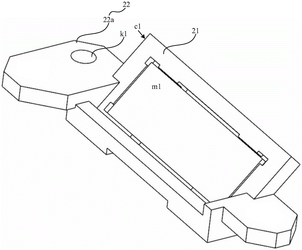
图2是本实用新型实施例提供的一种镜片调节组件的结构示意图,图3是图2所示的镜片调节组件的部分结构位于光学装置的壳体31内的结构示意图,图4是图2所示的镜片调节组件的以及光源组件的壳体的爆炸结构示意图,Figure 2 is a schematic structural view of a lens adjustment assembly provided by an embodiment of the present invention, Figure 3 is a structural schematic view of a part of the lens adjustment assembly shown in Figure 2 located in the
请参考图2、图3以及图4,该镜片调节组件包括:镜片安装支架21以及至少一个调节结构22。Please refer to FIG. 2 , FIG. 3 and FIG. 4 , the lens adjustment assembly includes: a
调节结构22包括调节片22a、以及第一调节件22b。The
镜片安装支架21包括镜片安装面m1,调节片22a与镜片安装支架21的侧面c1连接,且调节片22a所在的平面与镜片安装面m1相交。The
第一调节件22b穿过调节片22a,且固定于光学装置的壳体31的内部,第一调节件22b用于改变调节片22a在光学装置的壳体31内部的位置,和/或,姿态。The
综上所述,本实用新型实施例提供了一种镜片调节组件,该镜片调节组件包括镜片安装支架以及至少一个调节结构,该调节结构包括调节片以及第一调节件,调节片与镜片安装支架的侧面连接,第一调节件穿过调节片,且固定于光学装置的壳体的内部,以将镜片安装支架固定于光学装置的壳体内,后续通过第一调节件即可以对镜片安装支架中的镜片进行调整,无需在光学装置的壳体上设置开孔。解决了相关技术中镜片调节组件对于光学装置的密封性的影响较大的问题,实现了降低镜片调节组件对于光学装置的密封性的影响的效果。In summary, the embodiment of the present utility model provides a lens adjustment assembly, the lens adjustment assembly includes a lens mounting bracket and at least one adjustment structure, the adjustment structure includes an adjustment piece and a first adjustment piece, the adjustment piece and the lens installation bracket The side connection of the first adjustment part passes through the adjustment piece and is fixed inside the housing of the optical device to fix the lens mounting bracket in the housing of the optical device, and then the lens mounting bracket can be adjusted through the first adjustment part. The lens can be adjusted without having to provide openings on the housing of the optical device. It solves the problem in the related art that the lens adjustment component has a great influence on the sealing of the optical device, and realizes the effect of reducing the influence of the lens adjustment component on the sealing of the optical device.
另外,相关技术中由于光学装置的壳体存在开孔,为了降低该开孔对光学装置的密封性的影响,会在该开口处设置密封结构,该密封结构会对光学装置的壳体内外产生影响,且会增加光学装置的组装难度,而本实用新型实施例提供的镜片调节组件由于无需在光学装置的壳体上设置开孔,进而便能够降低对光学装置的壳体内外产生的影响。此外,在组装该光学装置时,可以在壳体未封闭时先对反射镜进行调整,并在完成调整之后对壳体进行密封操作,组装过程较为简单,降低了光学装置的组装难度。In addition, in the related art, since there is an opening in the housing of the optical device, in order to reduce the impact of the opening on the sealing of the optical device, a sealing structure is provided at the opening, which will cause damage to the inside and outside of the housing of the optical device. influence, and will increase the difficulty of assembling the optical device, and the lens adjustment assembly provided by the embodiment of the utility model can reduce the impact on the inside and outside of the housing of the optical device because no opening is required on the housing of the optical device. In addition, when assembling the optical device, the reflector can be adjusted first when the housing is not closed, and the housing can be sealed after the adjustment. The assembly process is relatively simple and the difficulty of assembling the optical device is reduced.
在一种示例性的实施例中,请参考图2、图3以及图4,第一调节件22b包括第一螺钉222、第一弹性件223以及第一固定结构224(图5示出的是第一弹性件223套在第一固定结构外的情况,但本实用新型实施例并不对此进行限制)。In an exemplary embodiment, please refer to FIG. 2, FIG. 3 and FIG. 4, the first adjusting
调节片22a与镜片安装支架21连接,且调节片22a上具有第一开孔k1。The adjusting
第一固定结构224固定于光学装置的壳体31内,且第一固定结构224上具有螺孔s1。The
第一螺钉222穿过调节片22a(穿过调节片22a上的第一开孔k1),并与第一固定结构224上的螺孔s1螺纹连接。The
第一弹性件223的一端与调节片22a连接,另一端与第一固定结构224或光学装置的壳体31连接。One end of the first
其中,第一固定结构224可以位于光学装置的壳体31的底部,如此可以便于从光学装置的壳体31的上部开口对第一螺钉222进行调节,降低了该镜片调节组件的调节难度。Wherein, the
需要说明的是,第一弹性件223的一端与调节片22a的连接可以为多种连接方式,例如可以为固定连接,或者,可以为抵接,类似的,第一弹性件223的另一端与第一固定结构224或光学装置的壳体31的连接也可以为多种连接方式,例如可以为固定连接,或者,可以为抵接。第一弹性件223的两端的连接用于限制第一弹性件223两端的移动,示例性的,当第一弹性件223为压缩状态时,第一弹性件223的两端的连接用于限制第一弹性件223伸长,当第一弹性件223为拉伸状态时,第一弹性件223的两端的连接用于限制第一弹性件223收缩。It should be noted that the connection between one end of the first
例如,当第一弹性件223为压缩状态时,第一弹性件223的一端可以与调节片22a抵接,另一端可以与第一固定结构224或光学装置的壳体31抵接。For example, when the first
图5是本实用新型实施例提供的另一种镜片调节组件的结构示意图,该镜片调节组件在图2所示的镜片调节组件的基础上进行了一些调整。FIG. 5 is a schematic structural view of another lens adjustment assembly provided by an embodiment of the present invention. The lens adjustment assembly has some adjustments on the basis of the lens adjustment assembly shown in FIG. 2 .
其中,调节结构22的数量为2,2个调节结构22中的两个调节片22a分别位于镜片安装支架21相对的两侧。位于镜片安装支架21相对的两侧的两个调节结构22可以在更多维度上对于镜片安装支架21中的镜片的姿态进行调整,提高了该镜片调节组件对于镜片的调节能力。Wherein, the number of the
当然,本实用新型实施例提供的镜片调节组件中,还可以具有更多个调节结构,例如三个调节结构、四个调节结构等,本实用新型实施例对此不进行限制。Of course, the lens adjustment assembly provided by the embodiment of the present invention may also have more adjustment structures, such as three adjustment structures, four adjustment structures, etc., which is not limited by the embodiment of the present invention.
在一种示例性的实施例中,两个调节片22a中的两个第一开孔k1,在镜片安装支架21的两侧对称设置,且两个第一开孔k1的中心的连线L,与镜片安装支架中的镜片平行(该与镜片平行可以是指该连线L与镜片的镜面平行)。如此对称的结构下,可以便于对镜片安装支架21中的镜片进行调节,降低镜片调节组件的调节难度。In an exemplary embodiment, the two first openings k1 in the two adjusting
在一种示例性的实施例中,镜片安装支架21中的镜片的几何中心,位于两个第一开孔的中心的连线L上。如此结构下,当一个第一开孔k1中的螺钉旋转,而另一个第一开孔k1中的螺钉不旋转,或者向相反方向旋转时,镜片安装支架21中的镜片即会绕经过自身的几何中心的一个轴线转动,调节便捷。如此便可以进一步降低镜片调节组件的调节难度。In an exemplary embodiment, the geometric center of the lens in the
图6是本实用新型实施例提供的另一种镜片调节组件的结构示意图,图7是图6所示的镜片调节组件的平面结构示意图,图8是图6所示的镜片调节组件位于光学装置的壳体时的爆炸结构示意图,请参考图6、图7以及图8,其中,两个调节结构中的至少一个调节结构22为目标调节结构22a,目标调节结构22a还包括第二螺钉225、第二弹性件226以及第二固定结构227。Figure 6 is a schematic structural view of another lens adjustment assembly provided by an embodiment of the present invention, Figure 7 is a schematic plan view of the lens adjustment assembly shown in Figure 6, and Figure 8 is a schematic view of the lens adjustment assembly shown in Figure 6 located in the optical device Please refer to FIG. 6 , FIG. 7 and FIG. 8 , wherein at least one
目标调节结构22a的调节片22a上还具有第二开孔k2,第二开孔k2的中心与两个第一开孔k1的中心不共线。图7示出的是第二开孔k2的中心与同一个调节片22a上的第一开孔k1的中心连线f,与连线L(该连线L为两个调节片22a上的两个第一开孔k1的中心的连线)之间垂直的情况,但连线f与连线L之间的夹角还可以为其他角度,例如该角度可以大于零度并小于180度。The adjusting
图9是图8所示的镜片调节组件中部分结构位于光源装置的壳体中的结构示意图,请参考图9,其中,第二固定结构227位于光学装置的壳体31内,且第二固定结构227上具有螺孔s2。FIG. 9 is a structural schematic view of part of the structure of the lens adjustment assembly shown in FIG. 8 located in the housing of the light source device. Please refer to FIG. The
请参考图8,第二螺钉225穿过调节片22a上的第二开孔k1,并与第二固定结构上的螺孔s2螺纹连接。Please refer to FIG. 8 , the
第二弹性件226的一端与调节片22a连接,另一端与第二固定结构或光学装置的壳体31连接。One end of the second
基于目标调节结构,当旋转第二螺钉225时,可以在更多维度下对镜片安装支架21的中的镜片的姿态进行调整。示例性的,当镜片安装支架21中的镜片的几何中心,位于两个第一开孔的中心的连线L上时,旋转第二螺钉225可以使镜片安装支架中的镜片以该经过该镜片的几何中心的另一个轴线(该轴线可以与调节第一螺钉时镜片转动的轴线具有锐角夹角)为轴转动。Based on the target adjustment structure, when the
图10是本实用新型实施例提供的一种镜片调节组件位于光学装置的壳体内的结构示意图,其中,第一弹性件223为第一弹簧2231,第一弹簧2231套在第一固定结构224外,且第一弹簧2231的一端与调节片22a抵接,第一弹2231簧的另一端与光学装置的壳体31抵接。Fig. 10 is a schematic structural diagram of a lens adjustment assembly provided by an embodiment of the present invention located in the housing of the optical device, wherein the first
在通过该镜片调节组件进行调节时,可以固定两个第一螺钉,并旋转第二螺钉,进而镜片安装支架中的镜片图7所示的连线L为轴转动。或者,可以同时旋转两个第一螺钉以及一个第二螺钉时,以对镜片安装支架中的镜片进行上升以及下降调节,或者,可以旋转目标调节结构中的第一螺钉以及第二螺钉,但不旋转另一个调节结构中的第一螺钉,以对镜片安装支架中的镜片进行另一方向的转动(该转动的轴线可以与连线L垂直)调节。或者,也可以不旋转目标调节结构中的第一螺钉以及第二螺钉,但旋转另一个调节结构中的第一螺钉时,也可以对镜片安装支架中的镜片进行转动调节。或者,也可以以第一方向旋转目标调节结构中的第一螺钉以及第二螺钉,并以第二方向(第一方向和第二方向中,一个方向可以为顺时针方向,另一个方向可以为逆时针方向)旋转另一个调节结构中的第一螺钉,以对镜片安装支架中的镜片进行转动调节。When adjusting through the lens adjusting assembly, two first screws can be fixed, and the second screw can be rotated, so that the lens in the lens mounting bracket can be rotated along the line L shown in FIG. 7 . Or, when two first screws and one second screw can be rotated at the same time, the lens in the lens mounting bracket can be adjusted up and down, or the first screw and the second screw in the target adjustment structure can be rotated, but not Rotate the first screw in another adjustment structure to adjust the lens in the lens mounting bracket to rotate in another direction (the axis of rotation may be perpendicular to the line L). Alternatively, the first screw and the second screw in the target adjustment structure may not be rotated, but the lens in the lens mounting bracket may also be rotated and adjusted when the first screw in another adjustment structure is rotated. Alternatively, the first screw and the second screw in the target adjustment structure can also be rotated in the first direction, and rotated in the second direction (in the first direction and the second direction, one direction can be clockwise, and the other direction can be counterclockwise) to rotate the first screw in another adjustment structure to adjust the rotation of the lens in the lens mounting bracket.
具体的,第一弹簧可以处于压缩状态,当旋转第一螺钉222时,第一螺钉22可以旋进第一固定结构224中的螺孔,或者旋出第一固定结构中的螺孔。当第一螺钉22旋进第一固定结构224中的螺孔时,可以向调节片22a施加压力,调节片22a将该压力传递至第一弹簧2231,并压缩第一弹簧2231,镜片安装支架中的镜片以经过该镜片的几何中心的轴线为轴向第三方向转动;当第一螺钉22旋出第一固定结构224中的螺孔时,第一弹簧伸长,调节片22a可以在第一弹簧伸长时施加的推力的作用下向远离第一固定结构的第四方向转动,镜片安装支架中的镜片以该经过该镜片的几何中心的轴线为轴向第二方向(第三方向和第四方向中,一个方向可以为顺时针方向,另一个方向可以为逆时针方向)转动。Specifically, the first spring may be in a compressed state, and when the
当然,第一弹性件还可以为其他结构,例如可以为弹性伸缩杆等,本实用新型实施例对此不进行限制。Certainly, the first elastic member may also be of other structures, for example, it may be an elastic telescopic rod, etc., which is not limited in this embodiment of the present utility model.
第二弹性件的结构可以参考第一弹性件,本实用新型实施例在此不再赘述。For the structure of the second elastic member, reference may be made to the first elastic member, which will not be repeated in this embodiment of the present invention.
图11是图10所示的镜片调节组件中部分区域的放大结构示意图,其中,镜片安装支架21包括镜片安装板211以及位于镜片安装板211上的镜片安装部212,镜片安装板211与调节片22a之间的夹角x大于零度且小于或等于90度。Fig. 11 is an enlarged structural diagram of a part of the lens adjustment assembly shown in Fig. 10, wherein the
由于镜片安装支架中的镜片可能会与光学装置的壳体的底部之间具有一定的夹角,以便于该镜片将光束反射向其他方向,进而当镜片安装板211与调节片22a之间的具有大于零度且小于或等于90度夹角x时,可以便于使第一固定结构、第二固定结构、第一螺钉以及第二螺钉能够与光学装置的壳体的底部垂直,以便于旋转第一螺钉以及第二螺钉。在一种示例性的实施例中该夹角x可以为45度。Because the lens in the lens mounting bracket may have a certain angle with the bottom of the housing of the optical device, so that the lens reflects the light beam to other directions, and then when there is a gap between the
光学装置的壳体的底部可以设置有发光单元(如激光器),该发光单元发出的光束可以垂直于光学装置的壳体的底部,当该夹角x为45度时,镜片可以接收发光单元发出的光束,并使反射光束与光学装置的壳体的底部平行,如此便于对光束进行控制以及调节。The bottom of the housing of the optical device can be provided with a light-emitting unit (such as a laser), and the light beam sent by the light-emitting unit can be perpendicular to the bottom of the housing of the optical device. When the included angle x is 45 degrees, the lens can receive The light beam, and make the reflected light beam parallel to the bottom of the housing of the optical device, so that it is easy to control and adjust the light beam.
请参考图11,镜片安装支架21包括镜片安装板211、位于镜片安装板211一面上的镜片安装部212以及镜片卡扣213。该镜片卡扣213可以用于将镜片固定与镜片安装部212中。在一种示例性的实施例中,镜片安装支架21可以包括两个镜片卡扣213,这两个镜片卡扣213可以位于镜片的两端,并将镜片的两端卡在镜片安装部212中。Please refer to FIG. 11 , the
图12是图11所示的镜片调节组件中的一种卡扣的结构示意图,图13是图12所示的卡扣的立体结构示意图,请参考图11、图12以及图13,其中,镜片卡扣213包括弹性臂2131、连接片2132以及背板2133,弹性臂2131、连接片2132以及背板2133依次连接,弹性臂2131被配置为与镜片安装部212(镜片安装部212也可称为镜片承靠面)中的镜片抵接,背板2133与镜片安装板212的背面b1贴合,镜片安装板212的背面b1与镜片安装板211中设置有镜片安装部的一面b2相对。Figure 12 is a schematic structural view of a buckle in the lens adjustment assembly shown in Figure 11, and Figure 13 is a schematic perspective view of the three-dimensional structure of the buckle shown in Figure 12, please refer to Figure 11, Figure 12 and Figure 13, wherein the lens The
请参考图11,镜片安装板212的背面b1还具有限位凸起t,镜片卡扣213的背板2133上具有开口c,限位凸起t卡在开口c中,以使镜片卡扣213卡在镜片安装板212上。该限位凸起t以及背板2133上具有开口c的组合,可以将限制镜片卡扣213的移动,以便于镜片卡扣213将镜片卡在镜片安装部212中。当然,本实用新型实施例提供的镜片调节组件中,还可以通过其他结构来将镜片固定与镜片安装部212中,本实用新型实施例对此不进行限制。Please refer to FIG. 11 , the back side b1 of the
综上所述,本实用新型实施例提供了一种镜片调节组件,该镜片调节组件包括镜片安装支架以及至少一个调节结构,该调节结构包括调节片以及第一调节件,调节片与镜片安装支架的侧面连接,第一调节件穿过调节片,且固定于光学装置的壳体的内部,以将镜片安装支架固定于光学装置的壳体内,后续通过第一调节件即可以对镜片安装支架中的镜片进行调整,无需在光学装置的壳体上设置开孔。解决了相关技术中镜片调节组件对于光学装置的密封性的影响较大的问题,实现了降低镜片调节组件对于光学装置的密封性的影响的效果。In summary, the embodiment of the present utility model provides a lens adjustment assembly, the lens adjustment assembly includes a lens mounting bracket and at least one adjustment structure, the adjustment structure includes an adjustment piece and a first adjustment piece, the adjustment piece and the lens installation bracket The side connection of the first adjustment part passes through the adjustment piece and is fixed inside the housing of the optical device to fix the lens mounting bracket in the housing of the optical device, and then the lens mounting bracket can be adjusted through the first adjustment part. The lens can be adjusted without having to provide openings on the housing of the optical device. It solves the problem in the related art that the lens adjustment component has a great influence on the sealing of the optical device, and realizes the effect of reducing the influence of the lens adjustment component on the sealing of the optical device.
另外,相关技术中由于光学装置的壳体存在开孔,为了降低该开孔对光学装置的密封性的影响,会在该开口处设置密封结构,该密封结构会对光学装置的壳体内外产生影响,且会增加光学装置的组装难度,而本实用新型实施例提供的镜片调节组件由于无需在光学装置的壳体上设置开孔,进而便能够降低对光学装置的壳体内外产生的影响,且降低了光学装置的组装难度。In addition, in the related art, since there is an opening in the housing of the optical device, in order to reduce the impact of the opening on the sealing of the optical device, a sealing structure is provided at the opening, which will cause damage to the inside and outside of the housing of the optical device. impact, and will increase the difficulty of assembling the optical device, and the lens adjustment assembly provided by the embodiment of the present invention does not need to provide an opening on the housing of the optical device, thereby reducing the impact on the inside and outside of the housing of the optical device, And the difficulty of assembling the optical device is reduced.
图14是本实用新型实施例提供的一种光学装置的平面结构示意图,该光学装置包括壳体31以及至少一个上述的镜片调节组件20,该镜片调节组件20位于壳体31中。FIG. 14 is a schematic plan view of an optical device provided by an embodiment of the present invention. The optical device includes a
在该光学装置包括多个镜片调节组件20时,这多个镜片调节组件20可以包括上述实施例提供的多种镜片调节组件20中的至少一种镜片调节组件20。When the optical device includes a plurality of
图15是图14所示的光学装置的爆炸结构示意图,图16是图14所示的光学装置在A-A处的剖面示意图,请参考图15以及图16,该光学装置包括两个镜片调节组件20,这两个调节组件20的结构可以相同,也可以不同,图15示出的是这两个镜片调节组件20的结构相同的情况,但并不对此进行限制。FIG. 15 is a schematic diagram of the exploded structure of the optical device shown in FIG. 14, and FIG. 16 is a schematic cross-sectional view of the optical device shown in FIG. 14 at A-A. Please refer to FIG. 15 and FIG. , the structures of the two
在光学装置包括两个镜片调节组件20,且这两个镜片调节组件20的结构均为图7所示的镜片调节组件20时,这两个镜片调节组件20可以整体呈L型,如图14所示,两个L型的镜片调节组件20中,一个镜片调节组件20可以呈正L型布局与光学装置的壳体中,另一个镜片调节组件20可以呈倒L型(即
综上所述,本实用新型实施例提供了一种光学装置,该光学装置中的镜片调节组件包括镜片安装支架以及至少一个调节结构,该调节结构包括调节片以及第一调节件,调节片与镜片安装支架的侧面连接,第一调节件穿过调节片,且固定于光学装置的壳体的内部,以将镜片安装支架固定于光学装置的壳体内,后续通过第一调节件即可以对镜片安装支架中的镜片进行调整,无需在光学装置的壳体上设置开孔。解决了相关技术中镜片调节组件对于光学装置的密封性的影响较大的问题,实现了降低镜片调节组件对于光学装置的密封性的影响的效果。In summary, the embodiment of the present invention provides an optical device, the lens adjustment assembly in the optical device includes a lens mounting bracket and at least one adjustment structure, the adjustment structure includes an adjustment piece and a first adjustment piece, the adjustment piece and the first adjustment piece The side of the lens mounting bracket is connected, the first adjusting piece passes through the adjusting piece, and is fixed inside the housing of the optical device, so that the lens mounting bracket is fixed in the housing of the optical device, and the lens can be adjusted through the first adjusting piece The lens in the mounting bracket is adjusted without having to provide an opening in the housing of the optical device. It solves the problem in the related art that the lens adjustment component has a great influence on the sealing of the optical device, and realizes the effect of reducing the influence of the lens adjustment component on the sealing of the optical device.
另外,相关技术中由于光学装置的壳体存在开孔,为了降低该开孔对光学装置的密封性的影响,会在该开口处设置密封结构,该密封结构会对光学装置的壳体内外产生影响,且会增加光学装置的组装难度,而本实用新型实施例提供的镜片调节组件由于无需在光学装置的壳体上设置开孔,进而便能够降低对光学装置的壳体内外产生的影响,且降低了光学装置的组装难度。In addition, in the related art, since there is an opening in the housing of the optical device, in order to reduce the impact of the opening on the sealing of the optical device, a sealing structure is provided at the opening, which will cause damage to the inside and outside of the housing of the optical device. impact, and will increase the difficulty of assembling the optical device, and the lens adjustment assembly provided by the embodiment of the present invention does not need to provide an opening on the housing of the optical device, thereby reducing the impact on the inside and outside of the housing of the optical device, And the difficulty of assembling the optical device is reduced.
此外,本实用新型实施例还可以提供一种投影仪,该投影仪可以包括上述实施例提供的光学装置。In addition, embodiments of the present utility model may also provide a projector, and the projector may include the optical device provided in the above embodiments.
本实用新型中术语“和/或”,仅仅是一种描述关联对象的关联关系,表示可以存在三种关系,例如,A和/或B,可以表示:单独存在A,同时存在A和B,单独存在B这三种情况。另外,本文中字符“/”,一般表示前后关联对象是一种“或”的关系。The term "and/or" in the present invention is only a kind of association relationship describing associated objects, which means that there may be three kinds of relationships, for example, A and/or B, which can mean: A exists alone, A and B exist simultaneously, There are three cases of B alone. In addition, the character "/" in this article generally indicates that the contextual objects are an "or" relationship.
本实用新型中术语“A和B的至少一种”,仅仅是一种描述关联对象的关联关系,表示可以存在三种关系,例如,A和B的至少一种,可以表示:单独存在A,同时存在A和B,单独存在B这三种情况。同理,“A、B和C的至少一种”表示可以存在七种关系,可以表示:单独存在A,单独存在B,单独存在C,同时存在A和B,同时存在A和C,同时存在C和B,同时存在A、B和C这七种情况。同理,“A、B、C和D的至少一种”表示可以存在十五种关系,可以表示:单独存在A,单独存在B,单独存在C,单独存在D,同时存在A和B,同时存在A和C,同时存在A和D,同时存在C和B,同时存在D和B,同时存在C和D,同时存在A、B和C,同时存在A、B和D,同时存在A、C和D,同时存在B、C和D,同时存在A、B、C和D,这十五种情况。The term "at least one of A and B" in the present utility model is only an association relationship describing associated objects, which means that there may be three kinds of relationships, for example, at least one of A and B can mean: A exists alone, There are three situations where A and B exist at the same time, and B exists alone. Similarly, "at least one of A, B, and C" means that seven relationships can exist, which can mean: A exists alone, B exists alone, C exists alone, A and B exist simultaneously, A and C exist simultaneously, and C and B, there are seven situations of A, B and C at the same time. Similarly, "at least one of A, B, C, and D" means that there can be fifteen relationships, which can mean: A exists alone, B exists alone, C exists alone, D exists alone, A and B exist simultaneously, and A and C, A and D, C and B, D and B, C and D, A, B, and C, A, B, and D, A, C and D, B, C, and D exist at the same time, and A, B, C, and D exist at the same time, these fifteen situations.
在本实用新型中,术语“第一”、“第二”、“第三”和“第四”仅用于描述目的,而不能理解为指示或暗示相对重要性。术语“多个”指两个或两个以上,除非另有明确的限定。In the present invention, the terms "first", "second", "third" and "fourth" are used for descriptive purposes only, and should not be understood as indicating or implying relative importance. The term "plurality" means two or more, unless otherwise clearly defined.
以上所述仅为本实用新型的可选实施例,并不用以限制本实用新型,凡在本实用新型的精神和原则之内,所作的任何修改、等同替换、改进等,均应包含在本实用新型的保护范围之内。The above descriptions are only optional embodiments of the present utility model, and are not intended to limit the present utility model. Any modifications, equivalent replacements, improvements, etc. made within the spirit and principles of the present utility model shall be included in this utility model. within the scope of protection of utility models.
Claims (10)
Priority Applications (1)
| Application Number | Priority Date | Filing Date | Title |
|---|---|---|---|
| CN202222758752.7U CN218630320U (en) | 2022-10-19 | 2022-10-19 | Lens adjusting assembly and optical device |
Applications Claiming Priority (1)
| Application Number | Priority Date | Filing Date | Title |
|---|---|---|---|
| CN202222758752.7U CN218630320U (en) | 2022-10-19 | 2022-10-19 | Lens adjusting assembly and optical device |
Publications (1)
| Publication Number | Publication Date |
|---|---|
| CN218630320U true CN218630320U (en) | 2023-03-14 |
Family
ID=85471711
Family Applications (1)
| Application Number | Title | Priority Date | Filing Date |
|---|---|---|---|
| CN202222758752.7U Active CN218630320U (en) | 2022-10-19 | 2022-10-19 | Lens adjusting assembly and optical device |
Country Status (1)
| Country | Link |
|---|---|
| CN (1) | CN218630320U (en) |
Cited By (1)
| Publication number | Priority date | Publication date | Assignee | Title |
|---|---|---|---|---|
| CN115494609A (en) * | 2022-10-19 | 2022-12-20 | 青岛海信激光显示股份有限公司 | Lens adjusting assembly and optical device |
-
2022
- 2022-10-19 CN CN202222758752.7U patent/CN218630320U/en active Active
Cited By (2)
| Publication number | Priority date | Publication date | Assignee | Title |
|---|---|---|---|---|
| CN115494609A (en) * | 2022-10-19 | 2022-12-20 | 青岛海信激光显示股份有限公司 | Lens adjusting assembly and optical device |
| CN115494609B (en) * | 2022-10-19 | 2025-09-16 | 青岛海信激光显示股份有限公司 | Lens adjusting assembly and optical device |
Similar Documents
| Publication | Publication Date | Title |
|---|---|---|
| US11803041B2 (en) | Prism module and folded lens using same | |
| US7901090B2 (en) | Adjustable reflective mirror module and projection apparatus using the same | |
| JP5166847B2 (en) | Projection display device | |
| US10365692B2 (en) | Display apparatus | |
| CN111198473A (en) | Opto-mechanical module | |
| CN114527570A (en) | Near-to-eye display optical system and head-mounted equipment | |
| CN110515199A (en) | Mirror adjustment mechanism and projection device | |
| CN216387541U (en) | Angle adjusting device of light reflector in projector | |
| US8016432B2 (en) | Projection apparatus | |
| CN117608154A (en) | Projectors and wearable devices | |
| US10890832B2 (en) | Optical device and optical module | |
| CN115494609A (en) | Lens adjusting assembly and optical device | |
| WO2020228506A1 (en) | Terminal device | |
| CN209044286U (en) | Opto-mechanical module | |
| CN204360708U (en) | A kind of vehicle-mounted head-up-display system and image display device wherein | |
| CN209514287U (en) | Optical module and projector | |
| CN119992972A (en) | A full-angle flexible splicing LED screen | |
| CN209248155U (en) | Mirror adjustment mechanism and projection device | |
| US10838288B2 (en) | Projection apparatus and imaging module thereof | |
| CN218158498U (en) | Projection lens and projection equipment | |
| CN217718368U (en) | Display device | |
| CN218383444U (en) | Prism motor and electronic equipment | |
| CN217157064U (en) | Digital micromirror device and projection device | |
| CN111812927A (en) | Optical modules and projectors | |
| WO2023165267A1 (en) | Prism assembly, prism motor, and electronic device |
Legal Events
| Date | Code | Title | Description |
|---|---|---|---|
| GR01 | Patent grant | ||
| GR01 | Patent grant |