CN218628921U - Optical lens detection device - Google Patents
Optical lens detection device Download PDFInfo
- Publication number
- CN218628921U CN218628921U CN202223281291.5U CN202223281291U CN218628921U CN 218628921 U CN218628921 U CN 218628921U CN 202223281291 U CN202223281291 U CN 202223281291U CN 218628921 U CN218628921 U CN 218628921U
- Authority
- CN
- China
- Prior art keywords
- lens
- base
- detection
- alignment
- optical lens
- Prior art date
- Legal status (The legal status is an assumption and is not a legal conclusion. Google has not performed a legal analysis and makes no representation as to the accuracy of the status listed.)
- Expired - Fee Related
Links
- 238000001514 detection method Methods 0.000 title claims abstract description 34
- 230000003287 optical effect Effects 0.000 title claims abstract description 21
- 230000007246 mechanism Effects 0.000 claims abstract description 35
- 238000007689 inspection Methods 0.000 claims description 5
- 238000009434 installation Methods 0.000 claims description 3
- 238000000034 method Methods 0.000 abstract description 4
- 230000008569 process Effects 0.000 abstract description 3
- 230000003028 elevating effect Effects 0.000 abstract 2
- 238000010586 diagram Methods 0.000 description 3
- 238000005516 engineering process Methods 0.000 description 2
- 230000009286 beneficial effect Effects 0.000 description 1
- 230000008859 change Effects 0.000 description 1
- 238000004040 coloring Methods 0.000 description 1
- 238000003384 imaging method Methods 0.000 description 1
- 230000006872 improvement Effects 0.000 description 1
- 239000000463 material Substances 0.000 description 1
- 230000004048 modification Effects 0.000 description 1
- 238000012986 modification Methods 0.000 description 1
- 239000000126 substance Substances 0.000 description 1
- 229920003002 synthetic resin Polymers 0.000 description 1
- 239000000057 synthetic resin Substances 0.000 description 1
Images


Landscapes
- Eyeglasses (AREA)
Abstract
本实用新型公开了一种光学透镜检测装置,属于光学透镜技术领域,本实用新型包括底座、底座上的旋转机构和旋转机构上的对正机构,所述的底座上设置有支板,所述的支板顶部安装有升降杆且升降杆底端连接有检测头,所述的旋转机构包括转动设置于所述的底座上的放置台,所述的放置台底部贴合有从动齿轮环。本实用新型设置有旋转机构实现对透镜在检测过程中的自动化旋转,放置台上设置有垫圈防止透镜与放置台直接接触而产生划痕,同时通过对正机构对透镜进行自动对正,提高检测精度,通过检测头对透镜进行检测并将结果显示在操作显示屏上,用机器取代了人工对透镜的操作,使得检测规范化,可重复性高,提高检测效率。
The utility model discloses an optical lens detection device, which belongs to the technical field of optical lenses. The utility model comprises a base, a rotating mechanism on the base and an alignment mechanism on the rotating mechanism. The base is provided with a support plate, and the An elevating rod is installed on the top of the support plate and a detection head is connected to the bottom end of the elevating rod. The rotating mechanism includes a placing table rotatably arranged on the base, and a driven gear ring is attached to the bottom of the placing table. The utility model is provided with a rotating mechanism to realize the automatic rotation of the lens during the detection process, and a gasket is provided on the placing table to prevent the lens from directly contacting with the placing table to cause scratches, and at the same time, the lens is automatically aligned through the alignment mechanism to improve detection. High precision, the lens is detected by the detection head and the result is displayed on the operation display screen, and the manual operation of the lens is replaced by a machine, which makes the detection standardized, highly repeatable, and improves the detection efficiency.
Description
技术领域technical field
本实用新型涉及光学透镜技术领域,具体为一种光学透镜检测装置。The utility model relates to the technical field of optical lenses, in particular to an optical lens detection device.
背景技术Background technique
透镜是用透明物质制成的表面为球面一部分的光学元件,透镜是根据光的折射规律制成的,其折射面是两个球面或一个球面一个平面的透明体,依其外形的不同,可分为凸透镜和凹透镜两大类。透镜可广泛应用于安防、车载、数码相机、激光、光学仪器等各个领域,随着市场不断的发展,透镜技术的应用越来越广泛。A lens is an optical element whose surface is a part of a sphere made of a transparent substance. The lens is made according to the law of refraction of light. The refraction surface is a transparent body with two spheres or one sphere and one plane. Divided into convex lens and concave lens two categories. Lens can be widely used in various fields such as security, vehicle, digital camera, laser, optical instrument, etc. With the continuous development of the market, the application of lens technology is becoming more and more extensive.
合成树脂光学透镜因其不易粉碎、耐冲击强度高、重量轻、易着色、加工性优良等优点,有了很大发展,但它的缺点是硬度比较低,易擦划伤。光学透镜的偏芯不良,是导致镜头成像不良的主要原因,而现有的光学透镜检测装置在与透镜接触、对正、转动时极易划伤起毛而影响成品质量,因此在进行透镜偏芯检测时一般都是通过人工手动旋转镜片,通过目视偏芯仪里刻度线变化,进行偏芯的判断,效率较低且精度有限,所以我们提出了一种光学透镜检测装置,以便于解决上述中提出的问题。Synthetic resin optical lens has been greatly developed due to its advantages of not easy to crush, high impact resistance, light weight, easy coloring, and excellent processability, but its disadvantage is that it has relatively low hardness and is easy to scratch and scratch. Poor eccentricity of the optical lens is the main cause of poor imaging of the lens, and the existing optical lens inspection device is very easy to scratch and fluff when contacting, aligning, and rotating the lens, which will affect the quality of the finished product. Therefore, when performing lens eccentricity Generally, during detection, the lens is manually rotated, and the eccentricity is judged by visually observing the change of the scale line in the eccentricity meter. The efficiency is low and the accuracy is limited. Therefore, we propose an optical lens detection device to solve the above problems. questions raised in .
实用新型内容Utility model content
本实用新型的目的在于提供一种光学透镜检测装置,以解决上述背景技术提出的现有的光学透镜检测装置在与透镜接触、对正、转动时难免会造成划伤而通过人工手动旋转镜片效率较低且精度有限的问题。The purpose of this utility model is to provide an optical lens detection device to solve the problem that the existing optical lens detection device proposed by the above background technology will inevitably cause scratches when contacting, aligning and rotating the lens, and the efficiency of manually rotating the lens can be solved. Low and limited precision issues.
为实现上述目的,本实用新型提供一种光学透镜检测装置,包括底座、底座上的旋转机构和旋转机构上的对正机构,所述的底座上设置有支板,所述的支板顶部安装有升降杆且升降杆底端连接有检测头,所述的旋转机构包括转动设置于所述的底座上的放置台,所述的放置台底部贴合有从动齿轮环,所述的从动齿轮环底部连接有旋转支架,所述的底座上开设有与所述的旋转支架相适配的凹槽,所述的支板上开设有安装槽,所述的安装槽内安装有连接轴,所述的连接轴上设置有与所述的从动齿轮环相啮合的主动齿轮且连接轴的端部连接有电机,所述的放置台中心设有开孔且所述的放置台上且位于开孔的外侧设置有垫圈,所述的底座上连接有操作显示屏。In order to achieve the above purpose, the utility model provides an optical lens detection device, including a base, a rotating mechanism on the base and an alignment mechanism on the rotating mechanism, a support plate is arranged on the base, and the top of the support plate is installed There is a lifting rod and the bottom end of the lifting rod is connected with a detection head. The rotating mechanism includes a placing table that is rotatably arranged on the base. The bottom of the placing table is attached with a driven gear ring. The bottom of the gear ring is connected with a rotating bracket, the base is provided with a groove suitable for the rotating bracket, the support plate is provided with a mounting groove, and a connecting shaft is installed in the mounting groove. The connecting shaft is provided with a driving gear meshed with the driven gear ring and the end of the connecting shaft is connected with a motor, and the center of the placing platform is provided with an opening and is located on the placing platform. A washer is provided outside the opening, and an operation display screen is connected to the base.
优选的,所述的对正机构以所述的放置台的圆心为中心在放置台上中心对称设置有至少三组。Preferably, at least three sets of said aligning mechanisms are symmetrically arranged on the placing platform centered on the center of the placing platform.
优选的,所述的对正机构包括设置于所述的放置台上的对正轨,所述的对正轨内贯穿有螺杆,所述的螺杆端部连接有转子,所述的螺杆上活动连接有活动块,所述的活动块上连接有指向所述的放置台圆心方向设置的对正杆,所述的对正杆端部设置有接触头。Preferably, the alignment mechanism includes an alignment rail arranged on the placement table, a screw runs through the alignment rail, a rotor is connected to the end of the screw, and a rotor is movably connected to the screw. The movable block is connected with an alignment rod pointing to the center of the placing table, and the end of the alignment rod is provided with a contact head.
优选的,所述的电机与所述的操作显示屏信号连接。Preferably, the motor is signal-connected to the operation display screen.
优选的,所述的转子与所述的操作显示屏信号连接。Preferably, the rotor is signal-connected to the operation display screen.
与现有技术相比,本实用新型的有益效果是:本实用新型设置有旋转机构实现对透镜在检测过程中的自动化旋转,放置台上设置有垫圈防止透镜与放置台直接接触而产生划痕,同时通过对正机构对透镜进行自动对正,提高检测精度,通过检测头对透镜进行检测并将结果显示在操作显示屏上,用机器取代了人工对透镜的操作,使得检测规范化,可重复性高,提高检测效率。Compared with the prior art, the utility model has the beneficial effects that: the utility model is provided with a rotating mechanism to realize the automatic rotation of the lens during the detection process, and a gasket is provided on the placing platform to prevent the lens from directly contacting with the placing platform to cause scratches At the same time, the lens is automatically aligned through the alignment mechanism to improve the detection accuracy, the lens is detected through the detection head and the result is displayed on the operation display screen, and the manual operation of the lens is replaced by a machine, making the detection standardized and repeatable High performance, improve detection efficiency.
附图说明Description of drawings
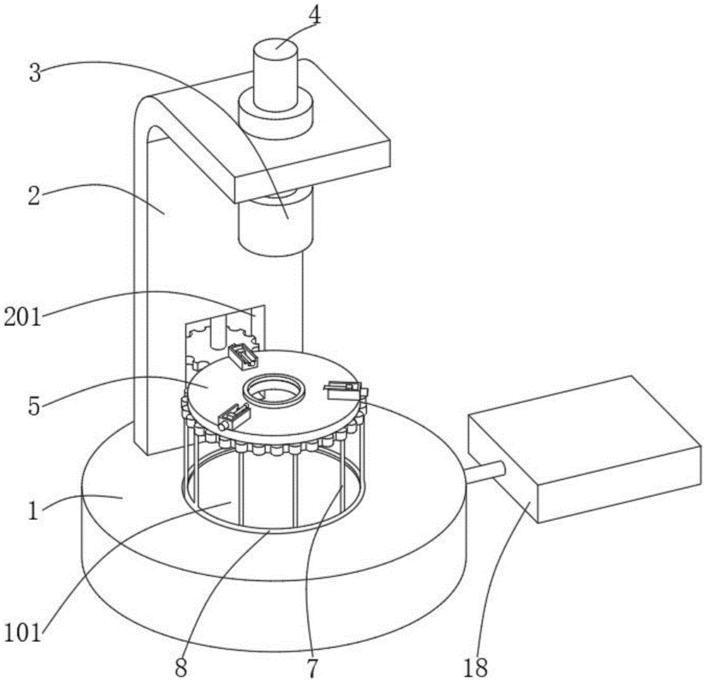
图1为本实用新型主体结构示意图;Fig. 1 is a schematic diagram of the main structure of the utility model;
图2为本实用新型旋转机构结构示意图;Fig. 2 is a structural schematic diagram of the utility model rotating mechanism;
图3为本实用新型对正机构结构示意图。Fig. 3 is a structural schematic diagram of the alignment mechanism of the present invention.
图中:1、底座;101、凹槽;2、支板;201、安装槽;3、检测头;4、升降杆;5、放置台;6、从动齿轮环;7、旋转支架;9、主动齿轮;10、连接轴;11、电机;12、垫圈;13、对正轨;14、螺杆;15、转子;16、活动块;17、对正杆;1701、接触头;18、操作显示屏。In the figure: 1, base; 101, groove; 2, supporting plate; 201, installation groove; 3, detection head; 4, lifting rod; 5, placing platform; 6, driven gear ring; 7, rotating bracket; 9 , driving gear; 10, connecting shaft; 11, motor; 12, washer; 13, alignment rail; 14, screw; 15, rotor; 16, movable block; 17, alignment rod; 1701, contact head; 18, operation display Screen.
具体实施方式Detailed ways
下面将结合本实用新型实施例中的附图,对本实用新型实施例中的技术方案进行清楚、完整地描述,显然,所描述的实施例仅仅是本实用新型一部分实施例,而不是全部的实施例。基于本实用新型中的实施例,本领域普通技术人员在没有做出创造性劳动前提下所获得的所有其他实施例,都属于本实用新型保护的范围。The technical solutions in the embodiments of the present invention will be clearly and completely described below in conjunction with the accompanying drawings in the embodiments of the present invention. Obviously, the described embodiments are only part of the embodiments of the present invention, not all of them. example. Based on the embodiments of the present utility model, all other embodiments obtained by persons of ordinary skill in the art without making creative efforts belong to the scope of protection of the present utility model.
请参阅图1-图3,本实用新型提供一种光学透镜检测装置,包括底座1、底座1上的旋转机构和旋转机构上的对正机构,底座1上设置有支板2,支板2顶部安装有升降杆4且升降杆4底端连接有检测头3,旋转机构包括转动设置于底座1上的放置台5,放置台5底部贴合有从动齿轮环6,从动齿轮环6底部连接有旋转支架7,底座1上开设有与旋转支架7相适配的凹槽101,支板2上开设有安装槽201,安装槽201内安装有连接轴10,连接轴10上设置有与从动齿轮环6相啮合的主动齿轮9且连接轴10的端部连接有电机11,放置台5中心设有开孔且放置台5上且位于开孔的外侧设置有垫圈12,底座1上连接有操作显示屏18。Please refer to Fig. 1-Fig. 3, the utility model provides a kind of optical lens detection device, comprises
对正机构以放置台5的圆心为中心在放置台5上中心对称设置有至少三组。There are at least three sets of aligning mechanisms arranged symmetrically on the
对正机构包括设置于放置台5上的对正轨13,对正轨13内贯穿有螺杆14,螺杆14端部连接有转子15,螺杆14上活动连接有活动块16,活动块16上连接有指向放置台5圆心方向设置的对正杆17,对正杆17端部设置有接触头1701。The alignment mechanism includes an
电机11与操作显示屏18信号连接。
转子15与操作显示屏18信号连接。The
实施例一Embodiment one
请参阅图1-图3,本实用新型提供一种光学透镜检测装置,包括底座1、底座1上的旋转机构和旋转机构上的对正机构,底座1上设置有支板2,支板2顶部安装有升降杆4且升降杆4底端连接有检测头3,通过操纵升降杆4来调整检测头3的高度,以适配透镜的检测。Please refer to Fig. 1-Fig. 3, the utility model provides a kind of optical lens detection device, comprises
旋转机构包括转动设置于底座1上的放置台5,放置台5底部贴合有从动齿轮环6,从动齿轮环6底部连接有旋转支架7,底座1上开设有与旋转支架7相适配的凹槽101,支板2上开设有安装槽201,安装槽201内安装有连接轴10,连接轴10上设置有与从动齿轮环6相啮合的主动齿轮9且连接轴10的端部连接有电机11,底座1上连接有操作显示屏18,电机11与操作显示屏18信号连接,通过操作显示屏18驱动电机11,电机11带动主动齿轮9转动,主动齿轮9带动从动齿轮环6转动,从而带动放置台5及其上的透镜进行旋转,旋转支架7在凹槽101内转动,从而实现透镜在检测过程中的自动化旋转,代替人工操作旋转透镜。The rotating mechanism includes a placing
放置台5中心设有开孔且放置台5上且位于开孔的外侧设置有垫圈12,防止透镜与放置台5直接接触而产生划痕。An opening is provided in the center of the placing table 5 and a
对正机构以放置台5的圆心为中心在放置台5上中心对称设置有三组。对正机构包括设置于放置台5上的对正轨13,对正轨13内贯穿有螺杆14,螺杆14端部连接有转子15,转子15与操作显示屏18信号连接,螺杆14上活动连接有活动块16,活动块16上连接有指向放置台5圆心方向设置的对正杆17,对正杆17端部设置有接触头1701。通过操作显示屏18驱动转子15,转子15带动螺杆14转动,使得活动块16在螺杆14上移动,从而带动对正杆17对透镜进行抵接对正,接触头1701与透镜的边缘接触,可设置为软橡胶材质,避免产生划痕,从而实现对透镜的对正和固定,提高检测精度。There are three sets of aligning mechanisms arranged symmetrically on the center of the
将透镜放置于放置台5上的垫圈12上,通过对正机构对透镜进行对正和固定,通过旋转机构对透镜实现自动化旋转,通过检测头3对透镜进行检测,并将结果显示在操作显示屏18上,用机器取代了人工对透镜的操作,使得检测规范化,可重复性高,提高检测效率。Place the lens on the
本说明书中未作详细描述的内容均属于本领域专业技术人员公知的现有技术。The contents not described in detail in this specification belong to the prior art known to those skilled in the art.
尽管参照前述实施例对本实用新型进行了详细的说明,对于本领域的技术人员来说,其依然可以对前述各实施例所记载的技术方案进行修改,或者对其中部分技术特征进行等同替换,凡在本实用新型的精神和原则之内,所做的任何修改、等同替换、改进等,均应包含在本实用新型的保护范围之内。Although the utility model has been described in detail with reference to the aforementioned embodiments, those skilled in the art can modify the technical solutions described in the aforementioned embodiments, or perform equivalent replacements for some of the technical features. Within the spirit and principles of the present utility model, any modification, equivalent replacement, improvement, etc. should be included in the protection scope of the present utility model.
Claims (5)
Priority Applications (1)
| Application Number | Priority Date | Filing Date | Title |
|---|---|---|---|
| CN202223281291.5U CN218628921U (en) | 2022-12-08 | 2022-12-08 | Optical lens detection device |
Applications Claiming Priority (1)
| Application Number | Priority Date | Filing Date | Title |
|---|---|---|---|
| CN202223281291.5U CN218628921U (en) | 2022-12-08 | 2022-12-08 | Optical lens detection device |
Publications (1)
| Publication Number | Publication Date |
|---|---|
| CN218628921U true CN218628921U (en) | 2023-03-14 |
Family
ID=85453908
Family Applications (1)
| Application Number | Title | Priority Date | Filing Date |
|---|---|---|---|
| CN202223281291.5U Expired - Fee Related CN218628921U (en) | 2022-12-08 | 2022-12-08 | Optical lens detection device |
Country Status (1)
| Country | Link |
|---|---|
| CN (1) | CN218628921U (en) |
-
2022
- 2022-12-08 CN CN202223281291.5U patent/CN218628921U/en not_active Expired - Fee Related
Similar Documents
| Publication | Publication Date | Title |
|---|---|---|
| CN209406712U (en) | A kind of five axis dispenser systems | |
| CN112557348B (en) | Convenient-to-use retroreflection coefficient tester | |
| CN110455505B (en) | A lens eccentricity measuring instrument | |
| CN115791605A (en) | Coating film adhesive force testing and recognizing instrument | |
| CN217930173U (en) | Double-light-source large-visual-field image measuring instrument | |
| CN205139045U (en) | Automated inspection equipment of contact lens defect | |
| CN208421395U (en) | A kind of Optical devices of multi-angle observation | |
| CN115420467A (en) | Medical oblique-viewing endoscope entrance pupil field angle and viewing direction angle detection device and method | |
| CN213689416U (en) | Glassware detection system | |
| CN221706486U (en) | Optical lens thickness detection device | |
| CN216694867U (en) | Optical eccentricity testing device for infrared lens | |
| CN220961297U (en) | Liquid microscope for detecting intraocular lens and contact lens | |
| CN219573949U (en) | Optical filter mirror defect detection device | |
| CN220305163U (en) | High light transmittance acrylic plate light transmittance testing device | |
| CN118858314A (en) | A liquid crystal display AOI online recognition device | |
| CN209416657U (en) | Flat Panel Display Optical Test Setup | |
| CN216744244U (en) | Optical device capable of simultaneously reproducing rainbow and neon | |
| WO2020191967A1 (en) | Detection method for smooth surface defects and detection device therefor | |
| CN211452242U (en) | Full-automatic assembly and visual detection equipment | |
| CN211927698U (en) | Transparency check out test set of surface water | |
| CN210072251U (en) | Device for detecting illumination visual angle of liquid crystal display | |
| CN210834703U (en) | Defect detecting and positioning device for reflector | |
| CN211505216U (en) | Silk screen printing equipment of carousel mechanism | |
| CN220398856U (en) | A contrast detection device suitable for 3D lenses | |
| CN218239880U (en) | Defect detection equipment for photoelectric optical lens |
Legal Events
| Date | Code | Title | Description |
|---|---|---|---|
| GR01 | Patent grant | ||
| GR01 | Patent grant | ||
| CF01 | Termination of patent right due to non-payment of annual fee | ||
| CF01 | Termination of patent right due to non-payment of annual fee |
Granted publication date: 20230314 |