CN218621068U - Hydrogen production cabin based on photovoltaic direct current direct coupling heating - Google Patents
Hydrogen production cabin based on photovoltaic direct current direct coupling heating Download PDFInfo
- Publication number
- CN218621068U CN218621068U CN202221702545.3U CN202221702545U CN218621068U CN 218621068 U CN218621068 U CN 218621068U CN 202221702545 U CN202221702545 U CN 202221702545U CN 218621068 U CN218621068 U CN 218621068U
- Authority
- CN
- China
- Prior art keywords
- hydrogen production
- photovoltaic
- heater
- hydrogen
- production cabin
- Prior art date
- Legal status (The legal status is an assumption and is not a legal conclusion. Google has not performed a legal analysis and makes no representation as to the accuracy of the status listed.)
- Expired - Fee Related
Links
Images

Landscapes
- Separation Using Semi-Permeable Membranes (AREA)
Abstract
本实用新型提出一种基于光伏直流直接耦合加热的制氢舱,包括:光伏发电加热器、制氢舱、电解槽、膜滤氢装置、换热系统;光伏发电加热器与换热系统连接;所述的制氢舱置于地面,其中制氢舱顶部为穹顶设计,膜滤氢装置安装在穹顶的顶部;所述的光伏发电加热器包括光伏组串和加热器,其中,光伏组串置于制氢舱的上部,所述的光伏组串包括多个矩形光伏发电组件,光伏发电组件按照阵列布置,加热器分布于换热系统相变储热材料中,所述的加热器是电加热丝,绕制成螺旋管形状;光伏组串正极与加热器正极连接,光伏组串负极与加热器负极连接,所述的电解槽置于制氢舱底面。
The utility model proposes a hydrogen production cabin based on photovoltaic DC direct coupling heating, including: a photovoltaic power generation heater, a hydrogen production cabin, an electrolytic cell, a membrane hydrogen filter device, and a heat exchange system; the photovoltaic power generation heater is connected to the heat exchange system; The hydrogen production cabin is placed on the ground, wherein the top of the hydrogen production cabin is designed as a dome, and the membrane hydrogen filtration device is installed on the top of the dome; the photovoltaic power generation heater includes a photovoltaic string and a heater, wherein the photovoltaic string is placed On the upper part of the hydrogen production cabin, the photovoltaic string includes a plurality of rectangular photovoltaic power generation components, the photovoltaic power generation components are arranged in an array, and the heater is distributed in the phase change heat storage material of the heat exchange system. The heater is an electric heating The wire is wound into a spiral tube shape; the positive electrode of the photovoltaic string is connected to the positive electrode of the heater, the negative electrode of the photovoltaic string is connected to the negative electrode of the heater, and the electrolyzer is placed on the bottom of the hydrogen production tank.
Description
技术领域technical field
本实用新型涉及新能源领域,尤其涉及一种基于光伏直流直接耦合加热的制氢舱。The utility model relates to the field of new energy, in particular to a hydrogen production cabin based on photovoltaic DC direct coupling heating.
背景技术Background technique
氢能是能源转换的媒介,是二次能源的载体;大规模储能和调节能力,促进新能源的发展,光伏、风能等新能源发电的波动,制约着新能源的快速发展,同时光伏、风能等新能源的快速推进,消纳成为一个新的问题。而制氢恰恰可以消耗电力,在电力短缺时发电,本质上起到削峰填谷的作用。但是现有技术中,很少有利用太阳能加热辅助制氢温度控制的设备。Hydrogen energy is the medium of energy conversion and the carrier of secondary energy; large-scale energy storage and regulation capabilities promote the development of new energy, and fluctuations in power generation of new energy such as photovoltaic and wind energy restrict the rapid development of new energy. With the rapid advancement of wind energy and other new energy sources, consumption has become a new problem. Hydrogen production can just consume electricity and generate electricity when there is a shortage of electricity, which essentially plays the role of peak shaving and valley filling. However, in the prior art, there are few devices that use solar heating to assist hydrogen production temperature control.
制氢过程的安全性是非常重要的,尤其氢气密度远低于氮气等气体,会富集在室内的顶部,考虑制备氢气时氢气泄漏和富集,造成的危害,需快速排放到大气中。而制氢工艺及效率与温度有关,温度越高效率越高,通用的排气过程会携带大量的热被排出,由此排气与保温是对矛盾。The safety of the hydrogen production process is very important, especially the density of hydrogen is much lower than that of nitrogen and other gases, and it will be enriched at the top of the room. Considering the harm caused by hydrogen leakage and enrichment during hydrogen production, it needs to be quickly discharged into the atmosphere. The hydrogen production process and efficiency are related to temperature. The higher the temperature, the higher the efficiency. The general exhaust process will carry a large amount of heat to be discharged. Therefore, exhaust and heat preservation are contradictory.
实用新型内容Utility model content
本实用新型的目的是克服现有技术的缺点,为解决制氢过程氢气泄漏在制备车间聚集,利用膜技术排氢,降低安全隐患,同时利用光伏发电制热、相变材料储热,提高制氢效率、保证制氢舱温度和正压。The purpose of this utility model is to overcome the shortcomings of the prior art, in order to solve the accumulation of hydrogen leakage in the production workshop during the hydrogen production process, use membrane technology to discharge hydrogen, reduce potential safety hazards, and at the same time use photovoltaic power generation for heating and phase change materials for heat storage to improve production efficiency. Hydrogen efficiency, guaranteed hydrogen production cabin temperature and positive pressure.
本实用新型的技术方案为:一种基于光伏直流直接耦合加热的制氢舱,包括:The technical solution of the utility model is: a hydrogen production cabin based on photovoltaic DC direct coupling heating, including:
光伏发电加热器、制氢舱、电解槽、膜滤氢装置、换热系统;光伏发电加热器与换热系统连接;Photovoltaic power generation heater, hydrogen production cabin, electrolyzer, membrane hydrogen filtration device, heat exchange system; photovoltaic power generation heater is connected to the heat exchange system;
所述的制氢舱置于地面,其中制氢舱顶部为穹顶设计,膜滤氢装置安装在穹顶的顶部;The hydrogen production cabin is placed on the ground, wherein the top of the hydrogen production cabin is designed as a dome, and the membrane hydrogen filtration device is installed on the top of the dome;
所述的光伏发电加热器包括光伏组串和加热器,其中,光伏组串置于制氢舱的上部,所述的光伏组串包括多个矩形光伏发电组件,光伏发电组件按照阵列布置,加热器分布于换热系统相变储热材料中,所述的加热器是电加热丝,绕制成螺旋管形状;光伏组串正极与加热器正极连接,光伏组串负极与加热器负极连接。The photovoltaic power heater includes a photovoltaic string and a heater, wherein the photovoltaic string is placed on the upper part of the hydrogen production cabin, the photovoltaic string includes a plurality of rectangular photovoltaic power generation components, and the photovoltaic power generation components are arranged in an array to heat The heater is distributed in the phase change heat storage material of the heat exchange system. The heater is an electric heating wire wound into a spiral tube shape; the positive pole of the photovoltaic string is connected to the positive pole of the heater, and the negative pole of the photovoltaic string is connected to the negative pole of the heater.
所述的电解槽置于制氢舱底面。The electrolyzer is placed on the bottom of the hydrogen production tank.
有益效果:Beneficial effect:
本实用新型充分利用光伏发电加热器和相变储能技术产热和储热,提高制氢的效率。The utility model makes full use of the photovoltaic power generation heater and the phase change energy storage technology to generate and store heat, and improves the efficiency of hydrogen production.
附图说明Description of drawings
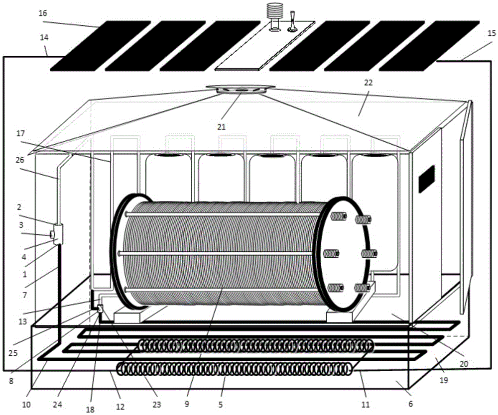
图1本实用新型一种基于光伏直流直接耦合加热的制氢舱示意图。Fig. 1 is a schematic diagram of a hydrogen production cabin based on photovoltaic DC direct coupling heating of the utility model.
其中:第一接口1,第二接口2,第三接口3,三通阀4,加热器5,相变储热材料6,换热器进水口7,温控分流阀门8,电解槽9,换热器10,加热器负极11,加热器正极12,散热器进水口13,光伏组串正极14,光伏组串负极15,光伏组串16,散热器17,换热器出水口18,密封箱体19,制氢舱20,膜滤氢装置21,穹顶22,出水口23,进水口24,分流管25,散热器出水管路26。Among them:
具体实施方式Detailed ways
下面将结合本实用新型实施例中的附图,对本实用新型实施例中的技术方案进行清楚、完整的描述,显然,所描述的实施例仅为本实用新型的一部分实施例,而不是全部的实施例,基于本实用新型中的实施例,本领域的普通技术人员在不付出创造性劳动的前提下所获得的所有其他实施例,都属于本实用新型的保护范围。The technical solutions in the embodiments of the present invention will be clearly and completely described below in conjunction with the accompanying drawings in the embodiments of the present invention. Obviously, the described embodiments are only part of the embodiments of the present invention, not all of them. Embodiments, based on the embodiments of the present utility model, all other embodiments obtained by persons of ordinary skill in the art without making creative efforts all belong to the protection scope of the present utility model.
实用新型根据本实用新型的一个实施例,如图1所示,一种基于光伏直流直接耦合加热的制氢舱,包括:光伏发电加热器、制氢舱20、电解槽9、膜滤氢装置21、换热系统;Utility model According to an embodiment of the utility model, as shown in Figure 1, a hydrogen production cabin based on photovoltaic DC direct coupling heating includes: photovoltaic power generation heater,
所述的制氢舱20置于地面,其中制氢舱顶部为穹顶22设计,膜滤氢装置21安装在穹顶22的顶部,由于氢气比重轻,利用穹顶21结构特点,将氢气富集在穹顶21的顶部,并通过膜滤氢装置21排出。The
所述的光伏发电加热器包括光伏组串16和加热器5。其中,光伏组串16置于制氢舱20的上部,所述的光伏组串包括多个矩形光伏发电组件,光伏发电组件按照阵列布置,光伏组串与膜滤氢装置21之间留有一定的空间,有利于氢气排放。加热器5分布式于换热系统相变储热材料6中,所述的加热器是电加热丝,绕制成螺旋管形状。光伏组串正极14与加热器正极12连接,光伏组串负极15与加热器负极11连接。光伏发电经加热器5转换成热能,并通过相变储热材料6将热能相变存储。The photovoltaic heater includes a
所述的膜滤氢装置21内包含滤氢膜、氢气传感器和引风机,在穹顶22顶部氢气富集时,当膜滤氢装置21中的氢气传感器监测出氢气达到一定的溶度时,引风机开启经滤氢膜将氢气排出。由于热量通过气体运动热交换传递,而氢气占制氢舱20内空气很小一部分,所携带温度有限,由此由于滤氢膜的存在,不会将大量的热量排出,大大减少热量的损失。The membrane
所述的电解槽9置于制氢舱20底面;The
所述的换热系统包括:相变储热材料6、换热器10、散热器17、三通阀4和温控分流阀门8。其中,相变储热材料6充填在密封箱体19内,置于制氢舱20内或其它室内周边;The heat exchange system includes: a phase change
换热器10安装在相变储热材料6中,并分别通过温控分流阀门8、三通阀4与安装在制氢舱20内的墙壁上散热器17连接,相变储热材料6通过吸收光伏发电加热器产生的热量存储,同时换热器10又将相变储热材料6中热量通过散热器17换热到制氢舱20内,制氢舱20内环境温度,有利于提高电解槽9制氢。The
其中,三通阀4中有3个接口分别为第一接口1与换热器进水口7连接,第二接口2与散热器出水管路26连接,第三接口3与供水口连接。Among them, there are three ports in the three-way valve 4, respectively, the
温控分流阀门8包括:进水口24、出水口23、分流管25。温控分流阀门8安装在换热器出水口18与散热器进水口13之间。其中,进水口24与换热器出水口18连接,出水口 23与散热器进水口13连接,分流管25与散热器出水管路26连接。其中,可依据环境温度调整温控分流阀门分流管25的出水流量,环境温度越高经分流管25的出水流量越多,散热器进水口13分流流量越少;反之,环境温度越低分流管25的出水流量越少,散热器进水口13分流流量越多,由此调整环境温度。The temperature-controlled shunt valve 8 includes: a
水流热量路径为换热器10将相变储热材料6换热,水流通过换热器出水口18经温控分流阀门进水口24,在温控分流阀门8分流,其中一部分热水在温控阀线性调节下经温控分流阀门出水口23、散热器进水口13分流到散热器17内,提供制氢舱20环境温度,提高制氢效率。另一部分经分流管25分流到散热器出水管路26中,再经三通阀4和换热器进水口7回流到换热器10中,完成一次热交换循环。The heat path of the water flow is that the
水流热量路径:相变储热材料6换热→换热器10→温控分流阀门8→散热器17→环境散热→三通阀4→换热器10。Heat path of water flow: heat exchange of phase change
其中,三通阀第三接口为注水口,补充换热系统中换热介质水。Among them, the third interface of the three-way valve is a water injection port, which supplements the heat exchange medium water in the heat exchange system.
尽管上面对本实用新型说明性的具体实施方式进行了描述,以便于本技术领域的技术人员理解本实用新型,且应该清楚,本实用新型不限于具体实施方式的范围,对本技术领域的普通技术人员来讲,只要各种变化在所附的权利要求限定和确定的本实用新型的精神和范围内,这些变化是显而易见的,一切利用本实用新型构思的实用新型创造均在保护之列。Although the specific implementation of the utility model has been described above, so that those skilled in the art can understand the utility model, and it should be clear that the utility model is not limited to the scope of the specific implementation, for those of ordinary skill in the art Speaking, as long as various changes are within the spirit and scope of the utility model defined and determined by the appended claims, these changes are obvious, and all utility model creations utilizing the concepts of the utility model are included in the protection list.
Claims (7)
Priority Applications (1)
| Application Number | Priority Date | Filing Date | Title |
|---|---|---|---|
| CN202221702545.3U CN218621068U (en) | 2022-07-04 | 2022-07-04 | Hydrogen production cabin based on photovoltaic direct current direct coupling heating |
Applications Claiming Priority (1)
| Application Number | Priority Date | Filing Date | Title |
|---|---|---|---|
| CN202221702545.3U CN218621068U (en) | 2022-07-04 | 2022-07-04 | Hydrogen production cabin based on photovoltaic direct current direct coupling heating |
Publications (1)
| Publication Number | Publication Date |
|---|---|
| CN218621068U true CN218621068U (en) | 2023-03-14 |
Family
ID=85456231
Family Applications (1)
| Application Number | Title | Priority Date | Filing Date |
|---|---|---|---|
| CN202221702545.3U Expired - Fee Related CN218621068U (en) | 2022-07-04 | 2022-07-04 | Hydrogen production cabin based on photovoltaic direct current direct coupling heating |
Country Status (1)
| Country | Link |
|---|---|
| CN (1) | CN218621068U (en) |
Cited By (1)
| Publication number | Priority date | Publication date | Assignee | Title |
|---|---|---|---|---|
| CN117109062A (en) * | 2023-08-03 | 2023-11-24 | 国核电力规划设计研究院有限公司 | Hydrogen station heating system |
-
2022
- 2022-07-04 CN CN202221702545.3U patent/CN218621068U/en not_active Expired - Fee Related
Cited By (1)
| Publication number | Priority date | Publication date | Assignee | Title |
|---|---|---|---|---|
| CN117109062A (en) * | 2023-08-03 | 2023-11-24 | 国核电力规划设计研究院有限公司 | Hydrogen station heating system |
Similar Documents
| Publication | Publication Date | Title |
|---|---|---|
| CN111139493B (en) | A kind of solar photovoltaic photothermal high temperature electrolysis water hydrogen production system and hydrogen production method | |
| CN110265691B (en) | A controllable hydrolysis hydrogen supply integrated system suitable for fuel cells | |
| CN104733748A (en) | Medium-high-temperature fuel cell integrated operation system | |
| CN203674322U (en) | Integrated operation system for middle and high-temperature fuel cell | |
| CN106486563A (en) | A kind of photovoltaic photo-thermal heat collector based on phase change thermal management | |
| CN114838611B (en) | High-temperature heat exchange and storage unit, structure and device | |
| CN217418822U (en) | Parallelly connected alkali lye circulation system device of electrolysis trough | |
| CN106784961A (en) | A kind of air distributor for anode support type tubular type SOFC battery piles | |
| CN203772087U (en) | Independent fused salt heat storage power plant | |
| CN115411315A (en) | Combined heat and power generation system of water electrolysis hydrogen production coupled metal solid hydrogen storage fuel cell | |
| CN214625114U (en) | Liquid hydrogen fuel cell waste heat recovery system | |
| CN201964813U (en) | High-temperature molten salt single-tank heat storage device with movable partition plate | |
| CN118431522A (en) | A thermal management device for a solid-state hydrogen storage integrated energy system | |
| CN218918959U (en) | Combined heat and power system | |
| CN107043149B (en) | A solar energy utilization system integrating photovoltaic power generation and photocatalytic water purification | |
| CN218621060U (en) | Phase-change heat storage membrane hydrogen filtration hydrogen production cabin utilizing solar heat energy | |
| CN201276573Y (en) | Temperature control device of marsh gas generator | |
| CN204227753U (en) | A kind of solar energy, biogas associating heat pump | |
| CN203454422U (en) | Air liquid type photovoltaic and photo-thermal heat exchange system | |
| CN115020768A (en) | A methanol-to-hydrogen fuel cell combined heat and power system | |
| CN218910545U (en) | Alkaline electrolyzed water hydrogen production tank and heat optimizing system | |
| CN217903163U (en) | A combined heat and power system | |
| CN217816970U (en) | The first station of a multi-energy complementary green energy heating network | |
| CN118347329A (en) | A packed bed heat storage system for solar multi-temperature zone heat cogeneration | |
| CN118224909A (en) | A solid-liquid two-phase heat storage system and working method thereof |
Legal Events
| Date | Code | Title | Description |
|---|---|---|---|
| GR01 | Patent grant | ||
| GR01 | Patent grant | ||
| CF01 | Termination of patent right due to non-payment of annual fee | ||
| CF01 | Termination of patent right due to non-payment of annual fee |
Granted publication date: 20230314 |