CN218613745U - Adjustable pipe tongs - Google Patents
Adjustable pipe tongs Download PDFInfo
- Publication number
- CN218613745U CN218613745U CN202223281617.4U CN202223281617U CN218613745U CN 218613745 U CN218613745 U CN 218613745U CN 202223281617 U CN202223281617 U CN 202223281617U CN 218613745 U CN218613745 U CN 218613745U
- Authority
- CN
- China
- Prior art keywords
- adjusting
- round
- handle
- shaped
- hole
- Prior art date
- Legal status (The legal status is an assumption and is not a legal conclusion. Google has not performed a legal analysis and makes no representation as to the accuracy of the status listed.)
- Expired - Fee Related
Links
Images


Landscapes
- Gripping Jigs, Holding Jigs, And Positioning Jigs (AREA)
Abstract
本实用新型公开了调节轻便的管钳,包括板状长柄、螺杆、圆盲孔、圆通孔、第一安装槽、圆弧钳头、钳座、轴承、正棱柱、圆杆、手柄、驱动齿轮、V形钳头、调节直柄、调节滑块、调节螺纹、调节螺母、从动齿轮、限位管、第二安装槽、调节滑槽。本实用新型结构简单、设计合理,能够使前管钳夹紧管道过程中,螺母调节轻便,使人们更加省力。
The utility model discloses a portable pipe wrench, which comprises a long plate-shaped handle, a screw rod, a round blind hole, a round through hole, a first installation groove, an arc pliers head, a pliers seat, a bearing, a positive prism, a round rod, a handle, and a drive. Gear, V-shaped pliers head, adjusting straight handle, adjusting slider, adjusting thread, adjusting nut, driven gear, limit pipe, second installation groove, adjusting chute. The utility model has the advantages of simple structure and reasonable design, and can make the adjustment of the nut convenient and convenient during the process of clamping the pipeline by the front pipe wrench, so that people can save more labor.
Description
【技术领域】【Technical field】
本实用新型涉及调节轻便的管钳的技术领域,特别是调节轻便的管钳的技术领域。The utility model relates to the technical field of adjusting portable pipe wrench, in particular to the technical field of adjusting portable pipe wrench.
【背景技术】【Background technique】
目前,管钳是拆装管路的常用工具,由于管钳开口的大小可以调节的功能,所以能广泛地适用于管路的拆装过程。虽然市面上管钳种类众多,但是目前在调节管钳时都是通过转动管钳前端的螺母来调节管钳的开口,例如申请号CN202020831655.4公开了一种调节轻便的管钳,该管钳通过转动螺母来调节活动钳口,申请号CN202220772102.5公开了一种管道施工用六角管钳该管钳通过转动调节环5来调节咬合部二7,申请号CN201920500987.1公开了一种伸缩式防爆管钳,该管钳通过旋转转轮4来调节活动爪,上述的这些螺母、调节环5、转轮4都是设在管钳前端的螺母小结构,我们在螺母体积小,我们能够接触并且用力的面积小,在螺母单独使用时,我们还需要借助扳手才能将螺母拧紧,在使用当前管钳时确是完全依靠我们手来转动,当管钳夹持管道之后,通过手来拧动螺母只能够实现对管道的轻度夹持,管道都是圆的,并非是六角螺母那样的形状,因此需要我们很用力的拧紧螺母才能让管钳的活动爪将管道压在固定爪上不易移动,进而通过管钳实现对管道的拿取、旋转等等操作,因此为了解决当前管钳夹紧管道过程中,螺母后期调节困难的问题,有必要提出调节轻便的管钳。At present, the pipe wrench is a common tool for disassembling and assembling pipelines. Because the size of the opening of the pipe wrench can be adjusted, it can be widely used in the process of disassembling and assembling pipelines. Although there are many types of pipe wrench on the market, at present, the opening of the pipe wrench is adjusted by turning the nut at the front end of the pipe wrench. For example, the application number CN202020831655. Adjust the movable jaw by turning the nut. Application No. CN202220772102.5 discloses a hexagonal pipe wrench for pipeline construction. Explosion-proof pipe wrench, the pipe wrench adjusts the movable claw by rotating the
【实用新型内容】【Content of utility model】
本实用新型的目的就是解决现有技术中的问题,提出调节轻便的管钳,能够使前管钳夹紧管道过程中,螺母调节轻便,使人们更加省力。The purpose of the utility model is to solve the problems in the prior art, and propose a light-adjustable pipe wrench, which can make the nut easy to adjust during the process of clamping the pipeline with the front pipe wrench, so that people can save more effort.
为实现上述目的,本实用新型提出了调节轻便的管钳,包括板状长柄、螺杆、圆盲孔、圆通孔、第一安装槽、圆弧钳头、钳座、轴承、正棱柱、圆杆、手柄、驱动齿轮、V形钳头、调节直柄、调节滑块、调节螺纹、调节螺母、从动齿轮、限位管、第二安装槽、调节滑槽,所述板状长柄左端面设有螺杆,螺杆左端面设有同轴的圆盲孔,圆盲孔孔底设有同轴的圆通孔,板状长柄左上端开设有经过圆盲孔的第一安装槽,板状长柄左侧设有圆弧钳头,圆弧钳头右端设有钳座,钳座右端面设有内螺纹盲孔,钳座拧在螺杆上,钳座右端面的内螺纹盲孔孔底设有同轴的轴承,轴承右端面设有同轴的正棱柱,正棱柱伸入圆盲孔内,第一安装槽内的正棱柱上设有同轴的驱动齿轮,正棱柱右端面设有同轴且穿过圆通孔的圆杆,板状长柄右侧设有固定在圆杆上的手柄,圆弧钳头左侧设有V形钳头,V形钳头V形口朝向圆弧钳头圆心设置,V形钳头右端设有位于板状长柄上方的调节直柄,调节直柄前端面、后端面设有调节滑块,调节直柄上端面、下端面设有调节螺纹,调节直柄上拧有与调节螺纹相配合的调节螺母,调节螺母外壁设有同轴的从动齿轮,从动齿轮与驱动齿轮啮合,限位管设在板状长柄左端,板状长柄左端、钳座、调节直柄均设在限位管内孔,限位管内孔设有与调节滑块相适配的调节滑槽,限位管上端开设有用来放置从动齿轮、驱动齿轮的第二安装槽。In order to achieve the above purpose, the utility model proposes a portable wrench for adjustment, including a long plate-shaped handle, a screw, a round blind hole, a round through hole, a first installation groove, an arc pliers head, a pliers seat, a bearing, a regular prism, a round Rod, handle, driving gear, V-shaped pliers head, adjusting straight handle, adjusting slider, adjusting thread, adjusting nut, driven gear, limit pipe, second installation groove, adjusting chute, the left end of the plate-shaped long handle There is a screw on the surface, a coaxial circular blind hole is provided on the left end of the screw, a coaxial round through hole is provided at the bottom of the circular blind hole, and the first installation groove passing through the circular blind hole is provided at the upper left end of the plate-shaped long handle. There is an arc pliers head on the left side of the long handle, a pliers seat on the right end of the arc pliers head, and an internal thread blind hole on the right end of the pliers seat. The pliers seat is screwed on the screw. For coaxial bearings, the right end of the bearing is provided with a coaxial positive prism, and the positive prism extends into the blind round hole. The positive prism in the first installation groove is provided with a coaxial drive gear, and the right end of the positive prism is provided with a coaxial And the round rod passing through the round through hole, the right side of the plate-shaped long handle is provided with a handle fixed on the round rod, the left side of the arc pliers head is provided with a V-shaped pliers head, and the V-shaped mouth of the V-shaped pliers head faces the arc pliers head The center of the circle is set, the right end of the V-shaped pliers head is provided with an adjustment straight handle above the long plate-shaped handle, the front end and rear end of the adjustment straight handle are provided with adjustment sliders, the upper end and lower end of the adjustment straight handle are provided with adjustment threads, and the adjustment straight An adjusting nut matching the adjusting thread is screwed on the handle, and a coaxial driven gear is arranged on the outer wall of the adjusting nut, and the driven gear meshes with the driving gear. Both the clamp seat and the adjusting straight handle are set in the inner hole of the limit tube, and the inner hole of the limit tube is provided with an adjustment chute matching the adjustment slider. groove.
作为优选,所述螺杆、圆盲孔、圆通孔、轴承、正棱柱、圆杆同轴,正棱柱、圆杆的设置方向与板状长柄长度方向一致。Preferably, the screw rod, the round blind hole, the round through hole, the bearing, the regular prism, and the round rod are coaxial, and the arrangement direction of the regular prism and the round rod is consistent with the length direction of the long plate-shaped shank.
作为优选,所述调节直柄与正棱柱、圆杆平行,调节滑块、调节滑槽均呈一字型,调节滑块、调节滑槽的设置方向均与调节直柄长度方向一致。As a preference, the adjusting straight handle is parallel to the regular prism and the round rod, the adjusting slider and the adjusting chute are in a straight shape, and the setting directions of the adjusting slider and the adjusting chute are consistent with the length direction of the adjusting straight handle.
作为优选,所述板状长柄左端、钳座均与限位管之间采用螺栓连接。As a preference, bolts are used to connect the left end of the long plate-shaped handle, the clamp seat and the limiting tube.
作为优选,所述圆弧钳头左端面设有若干个第一防滑齿牙,V形钳头的V形口内壁设有若干个第二防滑齿牙。Preferably, a plurality of first anti-slip teeth are provided on the left end surface of the arc-shaped pliers head, and a plurality of second anti-slip teeth are provided on the inner wall of the V-shaped opening of the V-shaped pliers head.
本实用新型的有益效果:本实用新型结构简单、设计合理,能够使前管钳夹紧管道过程中,螺母调节轻便,使人们更加省力;通过设置圆盲孔、圆通孔、第一安装槽、轴承、正棱柱、圆杆、手柄、驱动齿轮、从动齿轮的方式,以达到通过旋转手柄来驱动调节螺母的旋转的目的,相比直接推动调节螺母会更加省力。Beneficial effects of the utility model: the utility model is simple in structure and reasonable in design, and can make the nut easy to adjust during the process of clamping the pipeline by the front pipe wrench, making people more labor-saving; by setting round blind holes, round through holes, first installation grooves, Bearings, positive prisms, round rods, handles, driving gears, and driven gears are used to achieve the purpose of driving the rotation of the adjusting nut by rotating the handle, which is more labor-saving than directly pushing the adjusting nut.
本实用新型的特征及优点将通过实施例结合附图进行详细说明。The features and advantages of the utility model will be described in detail through embodiments in conjunction with the accompanying drawings.
【附图说明】【Description of drawings】
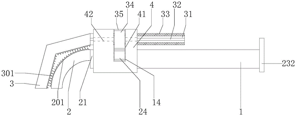
图1是本实用新型调节轻便的管钳的主视示意图;Fig. 1 is the schematic diagram of the front view of the portable pipe wrench of the utility model;
图2是本实用新型调节轻便的管钳的主视剖示意图。Fig. 2 is a schematic cross-sectional front view of the portable pipe wrench of the present invention.
【具体实施方式】【Detailed ways】
参阅图1、图2,本实用新型调节轻便的管钳,包括板状长柄1、螺杆11、圆盲孔12、圆通孔13、第一安装槽14、圆弧钳头2、钳座21、轴承22、正棱柱23、圆杆231、手柄232、驱动齿轮24、V形钳头3、调节直柄31、调节滑块32、调节螺纹33、调节螺母34、从动齿轮35、限位管4、第二安装槽41、调节滑槽42,所述板状长柄1左端面设有螺杆11,螺杆11左端面设有同轴的圆盲孔12,圆盲孔12孔底设有同轴的圆通孔13,板状长柄1左上端开设有经过圆盲孔12的第一安装槽14,板状长柄1左侧设有圆弧钳头2,圆弧钳头2右端设有钳座21,钳座21右端面设有内螺纹盲孔,钳座21拧在螺杆11上,钳座21右端面的内螺纹盲孔孔底设有同轴的轴承22,轴承22右端面设有同轴的正棱柱23,正棱柱23伸入圆盲孔12内,第一安装槽14内的正棱柱23上设有同轴的驱动齿轮24,正棱柱23右端面设有同轴且穿过圆通孔13的圆杆231,板状长柄1右侧设有固定在圆杆231上的手柄232,圆弧钳头2左侧设有V形钳头3,V形钳头3V形口朝向圆弧钳头2圆心设置,V形钳头3右端设有位于板状长柄1上方的调节直柄31,调节直柄31前端面、后端面设有调节滑块32,调节直柄31上端面、下端面设有调节螺纹33,调节直柄31上拧有与调节螺纹33相配合的调节螺母34,调节螺母34外壁设有同轴的从动齿轮35,从动齿轮35与驱动齿轮24啮合,限位管4设在板状长柄1左端,板状长柄1左端、钳座21、调节直柄31均设在限位管4内孔,限位管4内孔设有与调节滑块32相适配的调节滑槽42,限位管4上端开设有用来放置从动齿轮35、驱动齿轮24的第二安装槽41。Referring to Fig. 1 and Fig. 2, the portable pipe wrench of the utility model includes a plate-shaped long handle 1, a
其中,所述螺杆11、圆盲孔12、圆通孔13、轴承22、正棱柱23、圆杆231同轴,正棱柱23、圆杆231的设置方向与板状长柄1长度方向一致。Wherein, the
其中,所述调节直柄31与正棱柱23、圆杆231平行,调节滑块32、调节滑槽42均呈一字型,调节滑块32、调节滑槽42的设置方向均与调节直柄31长度方向一致。Wherein, the adjusting
其中,所述板状长柄1左端、钳座21均与限位管4之间采用螺栓连接。Wherein, the left end of the plate-shaped long handle 1 and the
其中,所述圆弧钳头2左端面设有若干个第一防滑齿牙201,V形钳头3的V形口内壁设有若干个第二防滑齿牙301。Wherein, a plurality of first
本实用新型工作过程:The working process of the utility model:
本实用新型调节轻便的管钳在工作过程,旋转手柄232,使正棱柱23、圆杆231转动,进而驱动齿轮24转动,通过从动齿轮35与驱动齿轮24之间的啮合连接来驱动调节螺母34转动,进而通过调节螺母34与调节螺纹33之间的螺纹配合来驱动调节直柄31左右移动,进而驱动V形钳头3远离或者靠近圆弧钳头2,由于调节螺母34的旋转使通过手柄232的转动来调节,相比直接推动调节螺母34会更加省力。The utility model adjusts the light pipe wrench in the working process, the
本实用新型结构简单、设计合理,能够使前管钳夹紧管道过程中,螺母调节轻便,使人们更加省力;通过设置圆盲孔12、圆通孔13、第一安装槽14、轴承22、正棱柱23、圆杆231、手柄232、驱动齿轮24、从动齿轮35的方式,以达到通过旋转手柄232来驱动调节螺母34的旋转的目的,相比直接推动调节螺母34会更加省力。The utility model is simple in structure and reasonable in design, and can make the nut easy to adjust during the process of clamping the pipeline by the front pipe wrench, making people more labor-saving; The
上述实施例是对本实用新型的说明,不是对本实用新型的限定,任何对本实用新型简单变换后的方案均属于本实用新型的保护范围。The above-mentioned embodiment is an illustration of the utility model, not a limitation of the utility model, and any scheme after a simple transformation of the utility model belongs to the protection scope of the utility model.
Claims (5)
Priority Applications (1)
| Application Number | Priority Date | Filing Date | Title |
|---|---|---|---|
| CN202223281617.4U CN218613745U (en) | 2022-12-06 | 2022-12-06 | Adjustable pipe tongs |
Applications Claiming Priority (1)
| Application Number | Priority Date | Filing Date | Title |
|---|---|---|---|
| CN202223281617.4U CN218613745U (en) | 2022-12-06 | 2022-12-06 | Adjustable pipe tongs |
Publications (1)
| Publication Number | Publication Date |
|---|---|
| CN218613745U true CN218613745U (en) | 2023-03-14 |
Family
ID=85453392
Family Applications (1)
| Application Number | Title | Priority Date | Filing Date |
|---|---|---|---|
| CN202223281617.4U Expired - Fee Related CN218613745U (en) | 2022-12-06 | 2022-12-06 | Adjustable pipe tongs |
Country Status (1)
| Country | Link |
|---|---|
| CN (1) | CN218613745U (en) |
-
2022
- 2022-12-06 CN CN202223281617.4U patent/CN218613745U/en not_active Expired - Fee Related
Similar Documents
| Publication | Publication Date | Title |
|---|---|---|
| CN204354037U (en) | Handheld manual presss from both sides loose bolt device | |
| CN204382153U (en) | Hand-held automatic clamp pine bolt device | |
| CN106272189A (en) | A kind of spanner being adapted to different nut diameter | |
| CN208147788U (en) | A kind of Portable multifunctional wrench | |
| CN221640719U (en) | Quick clamping pipe tongs | |
| CN114687683A (en) | Power tong back-up tong, power tong and application thereof | |
| CN219005880U (en) | Labor-saving pipe wrench dismounting device | |
| CN201046556Y (en) | Tap and die combination wrench | |
| CN212887340U (en) | An adjustable wrench with the functions of self-locking slider and rotating handle | |
| CN116214441A (en) | A labor-saving disassembly method for pipe wrench | |
| CN104786176A (en) | One-way self-clamping monkey wrench | |
| CN205928413U (en) | wrench | |
| CN217123012U (en) | A hexagonal pipe wrench for pipeline construction | |
| CN2889623Y (en) | Slotted Pull Lock Pipe Wrench | |
| CN201579730U (en) | chain wrench | |
| CN206047953U (en) | A kind of multidigit slides pincers | |
| CN211761101U (en) | Portable adjustable spanner | |
| CN206383084U (en) | A kind of opening-adjustable wrench | |
| CN216299132U (en) | An adjustable F-type valve wrench | |
| CN103465206A (en) | Multifunctional pipe tongs | |
| CN204673520U (en) | A kind of unidirectional from clamping shfting wrench | |
| WO2022109817A1 (en) | Nut wrench suitable for multiple sizes and method for using same | |
| CN112355980A (en) | Combined multifunctional adjustable wrench and using method thereof | |
| CN206287068U (en) | Drilling rod is clamped with new unloading | |
| CN222038359U (en) | Torque spanner |
Legal Events
| Date | Code | Title | Description |
|---|---|---|---|
| GR01 | Patent grant | ||
| GR01 | Patent grant | ||
| CF01 | Termination of patent right due to non-payment of annual fee |
Granted publication date: 20230314 |
|
| CF01 | Termination of patent right due to non-payment of annual fee |