CN218608989U - Chemical sand consolidation agent blending device - Google Patents
Chemical sand consolidation agent blending device Download PDFInfo
- Publication number
- CN218608989U CN218608989U CN202223002618.0U CN202223002618U CN218608989U CN 218608989 U CN218608989 U CN 218608989U CN 202223002618 U CN202223002618 U CN 202223002618U CN 218608989 U CN218608989 U CN 218608989U
- Authority
- CN
- China
- Prior art keywords
- box
- storage chamber
- liquid storage
- fixedly connected
- material guide
- Prior art date
- Legal status (The legal status is an assumption and is not a legal conclusion. Google has not performed a legal analysis and makes no representation as to the accuracy of the status listed.)
- Expired - Fee Related
Links
Images


Landscapes
- Feeding, Discharge, Calcimining, Fusing, And Gas-Generation Devices (AREA)
Abstract
本实用新型公开了一种化学固砂剂调配装置,包括调配箱,调配箱的前端面固定设置有透明窗,调配箱的顶部固定连接有供电箱,调配箱的两侧均固定连接有试剂箱,试剂箱的底部固定连接有支撑板,试剂箱的前端面固定设置有观察窗,试剂箱的内部开设有储液腔,两组储液腔相互远离的一侧均固定设置有进料管,且进料管与储液腔的内部相连通,储液腔的顶部固定安装有水泵,且水泵的输入端通过管道与储液腔的内部相连通。本实用新型通过设置的有调配箱、导料管、试剂箱、水泵、储液腔、液位传感器、暂存腔、混合腔、搅拌电机、导料孔、搅拌板、搅拌杆、导料阀和刮板,可以实现化学试剂不间断式的调配,从而可以提高生产量和生产效率。
The utility model discloses a compounding device for chemical sand-fixing agent, which comprises a compounding box, the front end of the compounding box is fixedly provided with a transparent window, the top of the compounding box is fixedly connected with a power supply box, and both sides of the compounding box are fixedly connected with a reagent box , the bottom of the reagent box is fixedly connected with a support plate, the front face of the reagent box is fixedly provided with an observation window, the inside of the reagent box is provided with a liquid storage chamber, and the sides of the two sets of liquid storage chambers away from each other are fixedly provided with feed pipes, In addition, the feeding pipe communicates with the inside of the liquid storage chamber, and a water pump is fixedly installed on the top of the liquid storage chamber, and the input end of the water pump communicates with the inside of the liquid storage chamber through a pipe. The utility model is equipped with a mixing box, a material guide pipe, a reagent box, a water pump, a liquid storage chamber, a liquid level sensor, a temporary storage chamber, a mixing chamber, a stirring motor, a material guide hole, a stirring plate, a stirring rod, and a material guide valve. And the scraper can realize the uninterrupted deployment of chemical reagents, so that the production capacity and production efficiency can be improved.
Description
技术领域technical field
本实用新型涉及调配装置技术领域,具体为一种化学固砂剂调配装置。The utility model relates to the technical field of blending devices, in particular to a blending device for chemical sand-consolidating agents.
背景技术Background technique
化学固沙是指在风沙危害地区,利用化学材料与工艺,对易产生沙害的沙丘或沙质地表建造一层能够防止风力吹扬又具有保持水分和改良沙地性质的固结层,以达到控制和改善沙害环境,提高沙地生产力的技术措施,在化学固砂剂制备过程中需要使用到调配装置对化学试剂进行调配。Chemical sand fixation refers to the use of chemical materials and techniques to build a layer of consolidation layer on sand dunes or sandy surfaces that are prone to sand damage in wind-sand hazard areas, which can prevent wind blowing, maintain moisture and improve sand properties, so as to achieve The technical measures to control and improve the environment of sand damage and increase the productivity of sandy land require the use of a blending device to blend chemical reagents during the preparation of chemical sand consolidation agents.
本申请在现有技术下进行改进,现有技术中,化学固砂剂的调配往往采用人工调配的方式,将各种化学试剂通过量具定量以后,进行混合搅拌配匀进行使用,这样虽然也能达到调配的目的,但当需要大量化学固砂剂的情况下,这样调配方式生产量小,生产效率低,无法很好的满足人们的使用需求。This application is improved under the existing technology. In the prior art, the deployment of chemical sand-consolidating agents often adopts the method of manual deployment. After the various chemical reagents are quantified by measuring tools, they are mixed and stirred evenly for use. Although this can also To achieve the purpose of deployment, but when a large amount of chemical sand consolidation agent is needed, the production volume of this deployment method is small, the production efficiency is low, and it cannot well meet people's use needs.
实用新型内容Utility model content
本实用新型的目的在于提供一种化学固砂剂调配装置,以解决上述背景技术中提出的问题。The purpose of this utility model is to provide a chemical sand-consolidating agent blending device to solve the problems raised in the above-mentioned background technology.
为实现上述目的,本实用新型提供如下技术方案:一种化学固砂剂调配装置,包括调配箱,所述调配箱的前端面固定设置有透明窗,所述调配箱的顶部固定连接有供电箱,所述调配箱的两侧均固定连接有试剂箱,所述试剂箱的底部固定连接有支撑板,所述试剂箱的前端面固定设置有观察窗,所述试剂箱的内部开设有储液腔,两组所述储液腔相互远离的一侧均固定设置有进料管,且进料管与储液腔的内部相连通,所述储液腔的顶部固定安装有水泵,且水泵的输入端通过管道与储液腔的内部相连通,所述水泵的输出端固定连接有导料管,所述调配箱的内部上端对称开设有暂存腔,且导料管与暂存腔的内部相连通,所述暂存腔的内壁固定安装有液位传感器,所述暂存腔的底部开设有混合腔。In order to achieve the above purpose, the utility model provides the following technical solutions: a chemical sand-fixing agent blending device, including a blending box, a transparent window is fixedly arranged on the front face of the blending box, and a power supply box is fixedly connected to the top of the blending box , both sides of the mixing box are fixedly connected with a reagent box, the bottom of the reagent box is fixedly connected with a support plate, the front end of the reagent box is fixedly provided with an observation window, and the inside of the reagent box is provided with a liquid storage Cavities, the sides of the two groups of liquid storage chambers far away from each other are fixed with feed pipes, and the feed pipes communicate with the inside of the liquid storage chambers, and a water pump is fixedly installed on the top of the liquid storage chambers, and the water pumps The input end communicates with the inside of the liquid storage chamber through a pipeline, the output end of the water pump is fixedly connected with a feed pipe, and the inner upper end of the mixing box is symmetrically provided with a temporary storage chamber, and the feed pipe is connected to the inside of the temporary storage chamber. A liquid level sensor is fixedly installed on the inner wall of the temporary storage chamber, and a mixing chamber is opened at the bottom of the temporary storage chamber.
作为本实用新型进一步的方案:所述混合腔与暂存腔之间开设有导料孔,且导料孔分别与混合腔和暂存腔的内部相连通,所述导料孔的内部固定安装有导料阀。As a further solution of the utility model: a material guide hole is provided between the mixing chamber and the temporary storage chamber, and the material guide holes are respectively connected with the inside of the mixing chamber and the temporary storage chamber, and the inside of the material guide hole is fixedly installed There is a feed valve.
作为本实用新型进一步的方案:所述混合腔的内部转动设置有搅拌杆,所述搅拌杆的顶部固定安装有搅拌电机,且搅拌电机的输出端与搅拌杆的顶部固定连接,所述搅拌杆的外壁对称分布有搅拌板,两组所述搅拌板相互远离的一侧均固定连接有刮板。As a further solution of the utility model: the inside of the mixing chamber is provided with a stirring rod, the top of the stirring rod is fixedly equipped with a stirring motor, and the output end of the stirring motor is fixedly connected with the top of the stirring rod, and the stirring rod Stirring plates are symmetrically distributed on the outer wall of the outer wall, and scrapers are fixedly connected to the sides of the two sets of stirring plates far away from each other.
作为本实用新型进一步的方案:所述混合腔底部的两侧均贯穿设置有下料管,且下料管与混合腔的内部相连通,所述下料管的内部固定安装有下料阀。As a further solution of the present invention: both sides of the bottom of the mixing chamber are provided with feeding pipes, and the feeding pipes communicate with the inside of the mixing chamber, and a feeding valve is fixedly installed inside the feeding pipe.
作为本实用新型进一步的方案:所述供电箱的内部安装有蓄电池,所述供电箱的前端面对称开设有散热孔,所述散热孔的内部固定设置有防尘网。As a further solution of the utility model: a storage battery is installed inside the power supply box, and cooling holes are symmetrically opened on the front end of the power supply box, and a dust-proof net is fixedly installed inside the cooling holes.
作为本实用新型进一步的方案:所述调配箱底部的两侧均固定连接有支柱,且支柱的数量为四个。As a further solution of the utility model: both sides of the bottom of the mixing box are fixedly connected with pillars, and the number of pillars is four.
与现有技术相比,本实用新型的有益效果是:该化学固砂剂调配装置,具有以下优点:Compared with the prior art, the beneficial effect of the utility model is that the chemical sand-consolidating agent preparation device has the following advantages:
(1)通过设置的有调配箱、导料管、试剂箱、水泵、储液腔、液位传感器、暂存腔、混合腔、搅拌电机、导料孔、搅拌板、搅拌杆、导料阀和刮板,可以实现化学试剂不间断式的调配,从而可以提高生产量和生产效率,解决了现有的化学固砂剂的调配往往采用人工调配的方式,将各种化学试剂通过量具定量以后,进行混合搅拌配匀进行使用,这样虽然也能达到调配的目的,但当需要大量化学固砂剂的情况下,这样调配方式生产量小,生产效率低,无法很好满足人们的使用需求的问题;(1) There are blending box, material guide pipe, reagent box, water pump, liquid storage chamber, liquid level sensor, temporary storage chamber, mixing chamber, stirring motor, material guide hole, stirring plate, stirring rod, and material guide valve. And the scraper can realize the uninterrupted deployment of chemical reagents, so as to improve the production capacity and production efficiency, and solve the problem that the existing chemical sand consolidation agent is often prepared manually, and various chemical reagents are quantified by measuring tools. , mixed and stirred evenly for use, although this can also achieve the purpose of deployment, but when a large amount of chemical sand consolidation agent is required, the production volume of this deployment method is small, the production efficiency is low, and it cannot well meet people's use needs. question;
(2)通过设置的有供电箱、散热孔、防尘网、进料管、观察窗和蓄电池,工作人员可以通过观察窗了解储液腔内化学试剂量,当化学试剂量较少时,通过进料管往储液腔内加入相适配的化学试剂,从而保证整个化学试剂调配的正常工作,且通过蓄电池的设置,当因某些原因意外断电时,能够通过蓄电池为该装置所需电器提高电力,从而保证整个装置的正常运作。(2) Through the installation of power supply box, heat dissipation hole, dust-proof net, feeding pipe, observation window and battery, the staff can know the amount of chemical reagent in the liquid storage chamber through the observation window. When the amount of chemical reagent is small, through The feed pipe adds suitable chemical reagents into the liquid storage chamber, so as to ensure the normal operation of the entire chemical reagent deployment, and through the setting of the battery, when the power is unexpectedly cut off due to some reasons, the battery can be used for the device. The electrical appliances boost the power to keep the entire unit functioning properly.
附图说明Description of drawings
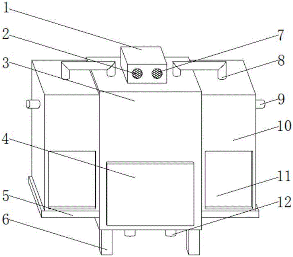
图1为本实用新型的整体结构立体示意图;Fig. 1 is the three-dimensional schematic view of the overall structure of the utility model;
图2为本实用新型的主视内部局部结构示意图;Fig. 2 is a schematic diagram of the internal partial structure of the main view of the utility model;
图3为本实用新型的A处放大局部结构示意图。Fig. 3 is a schematic diagram of an enlarged partial structure at A of the present invention.
图中:1、供电箱;2、散热孔;3、调配箱;4、透明窗;5、支撑板;6、支柱;7、防尘网;8、导料管;9、进料管;10、试剂箱;11、观察窗;12、下料管;13、水泵;14、储液腔;15、下料阀;16、蓄电池;17、液位传感器;18、暂存腔;19、混合腔;20、搅拌电机;21、导料孔;22、搅拌板;23、搅拌杆;24、导料阀;25、刮板。In the figure: 1. Power supply box; 2. Cooling hole; 3. Allocation box; 4. Transparent window; 5. Support plate; 6. Pillar; 7. Dust-proof net; 10. Reagent box; 11. Observation window; 12. Feed pipe; 13. Water pump; 14. Liquid storage chamber; 15. Feed valve; 16. Battery; 17. Liquid level sensor; 18. Temporary storage chamber; 19. Mixing cavity; 20, stirring motor; 21, material guide hole; 22, stirring plate; 23, stirring rod; 24, material guide valve; 25, scraper.
具体实施方式Detailed ways
为了使本领域技术人员更好地理解本实用新型的技术方案,下面结合附图对本实用新型进行详细描述,本部分的描述仅是示范性和解释性,不应对本实用新型的保护范围有任何的限制作用。In order to enable those skilled in the art to better understand the technical solution of the utility model, the utility model will be described in detail below in conjunction with the accompanying drawings. The description of this part is only exemplary and explanatory, and should not have any influence on the protection scope of the utility model. restrictive effect.
应注意到:相似的标号和字母在下面的附图中表示类似项,因此,一旦某一项在一个附图中被定义,则在随后的附图中不需要对其进行进一步定义和解释。It should be noted that like numerals and letters denote similar items in the following figures, therefore, once an item is defined in one figure, it does not require further definition and explanation in subsequent figures.
需要说明的是,术语“中心”、“上”、“下”、“左”、“右”、“竖直”、“水平”、“内”、“外”等指示的方位或位置关系为基于附图所示的方位或位置关系,或者是该实用新型产品使用时惯常摆放的方位或位置关系,仅是为了便于描述本实用新型和简化描述,而不是指示或暗示所指的装置或元件必须具有特定的方位、以特定的方位构造和操作,因此不能理解为对本实用新型的限制。此外,术语“第一”、“第二”、“第三”等仅用于区分描述,而不能理解为指示或暗示相对重要性。It should be noted that the orientation or positional relationship indicated by the terms "center", "upper", "lower", "left", "right", "vertical", "horizontal", "inner" and "outer" are Based on the orientation or positional relationship shown in the drawings, or the orientation or positional relationship that is usually placed when the utility model product is used, it is only for the convenience of describing the utility model and simplifying the description, rather than indicating or implying the referred device or Elements must have certain orientations, be constructed and operate in certain orientations, and thus should not be construed as limitations on the invention. In addition, the terms "first", "second", "third", etc. are only used for distinguishing descriptions, and should not be construed as indicating or implying relative importance.
此外,术语“水平”、“竖直”、“悬垂”等术语并不表示要求部件绝对水平或悬垂,而是可以稍微倾斜。如“水平”仅仅是指其方向相对“竖直”而言更加水平,并不是表示该结构一定要完全水平,而是可以稍微倾斜。In addition, the terms "horizontal", "vertical", "overhanging" and the like do not mean that the components are absolutely horizontal or overhanging, but may be slightly inclined. For example, "horizontal" only means that its direction is more horizontal than "vertical", and it does not mean that the structure must be completely horizontal, but can be slightly inclined.
在本实用新型的描述中,还需要说明的是,除非另有明确的规定和限定,术语“设置”、“安装”、“相连”、“连接”应做广义理解,例如,可以是固定连接,也可以是可拆卸连接,或一体地连接;可以是机械连接,也可以是电连接;可以是直接相连,也可以通过中间媒介间接相连,可以是两个元件内部的连通。对于本领域的普通技术人员而言,可以具体情况理解上述术语在本实用新型中的具体含义。In the description of the present utility model, it should also be noted that, unless otherwise specified and limited, the terms "setting", "installation", "connection" and "connection" should be understood in a broad sense, for example, it can be a fixed connection , can also be detachably connected, or integrally connected; can be mechanically connected, can also be electrically connected; can be directly connected, can also be indirectly connected through an intermediary, and can be internal communication between two components. Those of ordinary skill in the art can understand the specific meanings of the above terms in the present utility model in specific situations.
请参阅图1-3,本实用新型提供的一种实施例:一种化学固砂剂调配装置,包括调配箱3,调配箱3底部的两侧均固定连接有支柱6,且支柱6的数量为四个,调配箱3的前端面固定设置有透明窗4,调配箱3的顶部固定连接有供电箱1,供电箱1的内部安装有蓄电池16,供电箱1的前端面对称开设有散热孔2,散热孔2的内部固定设置有防尘网7,调配箱3的两侧均固定连接有试剂箱10,试剂箱10的底部固定连接有支撑板5,试剂箱10的前端面固定设置有观察窗11;Please refer to Figures 1-3, an embodiment provided by the utility model: a chemical sand-fixing agent deployment device, including a
具体的,如图1和图2所示,使用时,通过设置的有供电箱1、散热孔2、防尘网7、进料管9、观察窗11和蓄电池16,工作人员可以通过观察窗11了解储液腔14内化学试剂量,当化学试剂量较少时,通过进料管9往储液腔14内加入相适配的化学试剂,从而保证整个化学试剂调配的正常工作,且通过蓄电池16的设置,当因某些原因意外断电时,能够通过蓄电池16为该装置所需电器提高电力,从而保证整个装置的正常运作,并设置的散热孔2,便于对蓄电池16工作时产生的热量及时进行排散,设置有防尘网7,避免外界灰尘进入供电箱1内;Specifically, as shown in Figure 1 and Figure 2, when in use, through the
试剂箱10的内部开设有储液腔14,两组储液腔14相互远离的一侧均固定设置有进料管9,且进料管9与储液腔14的内部相连通,储液腔14的顶部固定安装有水泵13,且水泵13的输入端通过管道与储液腔14的内部相连通,水泵13的输出端固定连接有导料管8,调配箱3的内部上端对称开设有暂存腔18,且导料管8与暂存腔18的内部相连通,暂存腔18的内壁固定安装有液位传感器17,暂存腔18的底部开设有混合腔19,混合腔19与暂存腔18之间开设有导料孔21,且导料孔21分别与混合腔19和暂存腔18的内部相连通,导料孔21的内部固定安装有导料阀24,混合腔19的内部转动设置有搅拌杆23,搅拌杆23的顶部固定安装有搅拌电机20,且搅拌电机20的输出端与搅拌杆23的顶部固定连接,搅拌杆23的外壁对称分布有搅拌板22,两组搅拌板22相互远离的一侧均固定连接有刮板25,混合腔19底部的两侧均贯穿设置有下料管12,且下料管12与混合腔19的内部相连通,下料管12的内部固定安装有下料阀15;The inside of the
具体的,如图2和图3所示,使用时,通过设置的有调配箱3、导料管8、试剂箱10、水泵13、储液腔14、液位传感器17、暂存腔18、混合腔19、搅拌电机20、导料孔21、搅拌板22、搅拌杆23、导料阀24和刮板25,能够通过水泵13将储液腔14内的化学试剂通过导料管8送入暂存腔18内,且通过液位传感器17对暂存腔18内的液位进行检测,当暂存腔18内的液位达到液位传感器17的位置时,将信号传递给外设控制器,外设控制器控制水泵13停止工作,通过设置的有两组暂存腔18,可以对两组的化学试剂进行储存,液位传感器17也设置有多组,可以满足不同化学试剂需求量的检测目的,接着控制导料孔21内的导料阀24打开,使得暂存腔18内的化学试剂通过导料孔21全部进行混合腔19内,接着关闭导料阀24,并重复上一步操作,即向暂存腔18内添加化学试剂,同时控制搅拌电机20打开,能够通过搅拌电机20的输出端带动搅拌杆23旋转,搅拌杆23旋转带动搅拌板22旋转,从而对混合腔19内的化学试剂进行搅拌混合,当搅拌电机20的工作时间达到预先设置的时间时,即化学试剂调配完成后,控制下料阀15打开,使得混合腔19内调配完成的化学试剂通过下料管12全部流出,接着关闭下料阀15,并控制导料阀24打开,使得暂存腔18内的化学试剂再次进入混合腔19进行调配,通过这种不间断式的调配方式,可以提高进一步生产量和生产效率,解决了现有的化学固砂剂的调配往往采用人工调配的方式,将各种化学试剂通过量具定量以后,进行混合搅拌配匀进行使用,这样虽然也能达到调配的目的,但当需要大量化学固砂剂的情况下,这样调配方式生产量小,生产效率低,无法很好满足人们的使用需求的问题。Specifically, as shown in Figure 2 and Figure 3, when in use, there are a
工作原理:本申请中,当需要对两组化学试剂进行调配时,能够通过水泵13将储液腔14内的化学试剂通过导料管8送入暂存腔18内,且通过液位传感器17对暂存腔18内的液位进行检测,当暂存腔18内的液位达到液位传感器17的位置时,将信号传递给外设控制器,外设控制器控制水泵13停止工作,通过设置的有两组暂存腔18,可以对两组的化学试剂进行储存,液位传感器17也设置有多组,可以满足不同化学试剂需求量的检测目的,接着控制导料孔21内的导料阀24打开,使得暂存腔18内的化学试剂通过导料孔21全部进行混合腔19内,接着关闭导料阀24,并重复上一步操作,即向暂存腔18内添加化学试剂,同时控制搅拌电机20打开,能够通过搅拌电机20的输出端带动搅拌杆23旋转,搅拌杆23旋转带动搅拌板22旋转,从而对混合腔19内的化学试剂进行搅拌混合,当搅拌电机20的工作时间达到预先设置的时间时,即化学试剂调配完成后,控制下料阀15打开,使得混合腔19内调配完成的化学试剂通过下料管12全部流出,接着关闭下料阀15,并控制导料阀24打开,使得暂存腔18内的化学试剂再次进入混合腔19进行调配,通过这种不间断式的调配方式,可以提高进一步生产量和生产效率。Working principle: In this application, when two groups of chemical reagents need to be deployed, the chemical reagents in the
本申请文件中使用到的标准零件均可以从市场上购买,而且根据说明书和附图的记载均可以进行订制,各个零件的具体连接方式均采用现有技术中成熟的螺栓、铆钉、焊接等常规手段,机械、零件和设备均采用现有技术中常规的型号,同时本申请中出现的电器元件在使用时均外接连通电源和控制开关,控制方式是通过控制器来自动控制,控制器的控制电路通过本领域的技术人员简单编程即可实现,属于本领域的公知常识,所以本实用新型不再详细解释控制方式和电路连接,且说明书中提到的外设控制器可为本文提到的电器元件起到控制作用,而且该外设控制器为常规的已知设备。The standard parts used in this application document can be purchased from the market, and can be customized according to the instructions and drawings. The specific connection methods of each part adopt mature bolts, rivets, welding, etc. in the prior art. Conventional means, machinery, parts and equipment all adopt conventional models in the prior art. At the same time, the electrical components appearing in this application are connected with external power supply and control switch when in use. The control method is automatically controlled by the controller. The control circuit can be realized through simple programming by those skilled in the art, which belongs to common knowledge in the field, so the utility model does not explain the control method and circuit connection in detail, and the peripheral controller mentioned in the specification can be the The electrical components play a controlling role, and the peripheral controller is a conventional known device.
需要说明的是,在本文中,术语“包括”、“包含”或者其任何其他变体意在涵盖非排他性的包含,从而使得包括一系列要素的过程、方法、物品或者设备不仅包括那些要素,而且还包括没有明确列出的其他要素,或者是还包括为这种过程、方法、物品或者设备所固有的要素。It should be noted that, in this document, the terms "comprising", "comprising" or any other variation thereof are intended to cover a non-exclusive inclusion such that a process, method, article or apparatus comprising a set of elements includes not only those elements, It also includes other elements not expressly listed, or elements inherent in the process, method, article, or apparatus.
本文中应用了具体个例对本实用新型的原理及实施方式进行了阐述,以上实例的说明只是用于帮助理解本实用新型的方法及其核心思想。以上仅是本实用新型的优选实施方式,应当指出,由于文字表达的有限性,而客观上存在无限的具体结构,对于本技术领域的普通技术人员来说,在不脱离本实用新型原理的前提下,还可以做出若干改进、润饰或变化,也可以将上述技术特征以适当的方式进行组合;这些改进润饰、变化或组合,或未经改进将实用新型的构思和技术方案直接应用于其它场合的,均应视为本实用新型的保护范围。In this paper, specific examples are used to illustrate the principle and implementation of the present invention. The description of the above examples is only used to help understand the method and core idea of the present invention. The above are only preferred embodiments of the present utility model. It should be pointed out that due to the limitation of literal expression, there are objectively unlimited specific structures. Under these conditions, several improvements, modifications or changes can also be made, and the above-mentioned technical features can also be combined in an appropriate manner; these improvements, modifications, changes or combinations, or the ideas and technical solutions of the utility model can be directly applied to other Occasions, all should be regarded as the protection scope of the present utility model.
Claims (6)
Priority Applications (1)
| Application Number | Priority Date | Filing Date | Title |
|---|---|---|---|
| CN202223002618.0U CN218608989U (en) | 2022-11-07 | 2022-11-07 | Chemical sand consolidation agent blending device |
Applications Claiming Priority (1)
| Application Number | Priority Date | Filing Date | Title |
|---|---|---|---|
| CN202223002618.0U CN218608989U (en) | 2022-11-07 | 2022-11-07 | Chemical sand consolidation agent blending device |
Publications (1)
| Publication Number | Publication Date |
|---|---|
| CN218608989U true CN218608989U (en) | 2023-03-14 |
Family
ID=85446838
Family Applications (1)
| Application Number | Title | Priority Date | Filing Date |
|---|---|---|---|
| CN202223002618.0U Expired - Fee Related CN218608989U (en) | 2022-11-07 | 2022-11-07 | Chemical sand consolidation agent blending device |
Country Status (1)
| Country | Link |
|---|---|
| CN (1) | CN218608989U (en) |
-
2022
- 2022-11-07 CN CN202223002618.0U patent/CN218608989U/en not_active Expired - Fee Related
Similar Documents
| Publication | Publication Date | Title |
|---|---|---|
| US12157097B2 (en) | Fully electric-drive sand-mixing apparatus, and automatic control system for fully electric-drive sand-mixing apparatus | |
| CN105251403A (en) | Pressurized mixing device | |
| CN205570270U (en) | Useless powder humidification system of intelligence environment -friendly | |
| CN213091662U (en) | A new type of soil detection device | |
| CN209464971U (en) | A kind of mixing equipment for the preparation of aqueous zinc stearate | |
| CN206303196U (en) | A kind of full-automatic Hot and Sour Rice Noodles vermicelli machine | |
| CN217858002U (en) | Contaminated soil remediation agent permeator | |
| CN108253194B (en) | A pipeline installation device with ground repair function | |
| CN203090824U (en) | Manual blowing-type magnetic suspension preparation device | |
| CN213953524U (en) | Horizontal directional drilling machine cover | |
| CN214266168U (en) | Automatic mud mixer for drilling | |
| CN213323791U (en) | Automatic filling device used in production process of petroleum additive | |
| CN211838403U (en) | A dust-proof device for machine-made sand production | |
| CN210828210U (en) | Plastering machine for building construction | |
| CN209087204U (en) | Tsunami/gravity stream simulation generator under super gravity field | |
| CN208694740U (en) | A kind of easy-to-mount concrete admixture processing unit (plant) | |
| CN209132142U (en) | A civil engineering experimental detection device | |
| CN223505665U (en) | Adjustable V-shaped powder concentrator | |
| CN206746931U (en) | A kind of moulding integrated device of portable rubber mixing and coating | |
| CN219636887U (en) | Soybean dietary fiber production filling machine | |
| CN217126920U (en) | A single-scale automatic cashmere filling machine | |
| CN216825917U (en) | Energy-conserving coating agitated vessel is used in building engineering construction | |
| CN216654900U (en) | Putty powder production is with machine that grinds that has multiple screening structure | |
| CN218255937U (en) | Concrete compaction stirring device based on water conservancy construction is used | |
| CN211886824U (en) | Drilling fluid antifriction emollient preparation facilities |
Legal Events
| Date | Code | Title | Description |
|---|---|---|---|
| GR01 | Patent grant | ||
| GR01 | Patent grant | ||
| CF01 | Termination of patent right due to non-payment of annual fee | ||
| CF01 | Termination of patent right due to non-payment of annual fee |
Granted publication date: 20230314 |