CN218606364U - Dust accumulation preventing structure of dust collector floor brush - Google Patents
Dust accumulation preventing structure of dust collector floor brush Download PDFInfo
- Publication number
- CN218606364U CN218606364U CN202222902412.7U CN202222902412U CN218606364U CN 218606364 U CN218606364 U CN 218606364U CN 202222902412 U CN202222902412 U CN 202222902412U CN 218606364 U CN218606364 U CN 218606364U
- Authority
- CN
- China
- Prior art keywords
- dust
- rotating shaft
- brush
- rotating
- outside
- Prior art date
- Legal status (The legal status is an assumption and is not a legal conclusion. Google has not performed a legal analysis and makes no representation as to the accuracy of the status listed.)
- Active
Links
- 239000000428 dust Substances 0.000 title claims abstract description 82
- 238000009825 accumulation Methods 0.000 title claims abstract description 12
- 238000007789 sealing Methods 0.000 claims abstract description 17
- 230000007246 mechanism Effects 0.000 claims abstract description 14
- 238000010521 absorption reaction Methods 0.000 claims abstract description 12
- 238000005201 scrubbing Methods 0.000 claims abstract description 10
- 230000008021 deposition Effects 0.000 claims description 6
- 238000000034 method Methods 0.000 description 6
- XLYOFNOQVPJJNP-UHFFFAOYSA-N water Substances O XLYOFNOQVPJJNP-UHFFFAOYSA-N 0.000 description 5
- 230000008569 process Effects 0.000 description 4
- 230000009471 action Effects 0.000 description 3
- 239000000853 adhesive Substances 0.000 description 2
- 230000001070 adhesive effect Effects 0.000 description 2
- 230000004075 alteration Effects 0.000 description 1
- 230000009286 beneficial effect Effects 0.000 description 1
- 238000004140 cleaning Methods 0.000 description 1
- 238000006073 displacement reaction Methods 0.000 description 1
- 230000003434 inspiratory effect Effects 0.000 description 1
- 238000012986 modification Methods 0.000 description 1
- 230000004048 modification Effects 0.000 description 1
- 238000006467 substitution reaction Methods 0.000 description 1
Images

Landscapes
- Nozzles For Electric Vacuum Cleaners (AREA)
Abstract
The utility model discloses a dust accumulation structure is prevented to dust catcher scrubbing brush relates to dust catcher technical field. Including main part and wiper mechanism, dustproof sealing lid is installed in the outside of main part, dustproof sealing lid's bottom is connected with wiper mechanism. The utility model provides a dust accumulation structure is prevented to dust catcher scrubbing brush, through setting up wiper mechanism uses a period after the dust catcher, dust passes through the sunction inlet and gets into inside, it makes inboard total axle rotate to rotate outside knob, drive the spout internal rotation removal of rotor on the stationary blade, when making first pivot outside dust absorption rotary drum and second pivot drive brush self carry out reciprocal rotation, wholly carry out clockwise rotation, simply remove dust to inside, then the slider through the outside is punched the card the switch, put into the aquatic with the scrubbing brush, it is rotatory to make the motor drive the third pivot, outside fan blade is rotatory to drive the rivers and flows, carry out holistic clearance to inside, prevent the dust accumulation, the work efficiency is improved.
Description
Technical Field
The utility model relates to a dust catcher technical field especially relates to a dust accumulation structure is prevented to dust catcher scrubbing brush.
Background
The vacuum cleaner can be divided into a vertical type, a horizontal type and a portable type according to the structure, and the working principle of the vacuum cleaner is that a motor is used for driving blades to rotate at a high speed, air negative pressure is generated in a sealed shell, and dust is sucked. The vacuum cleaners are mainly classified into a household vacuum cleaner, a commercial vacuum cleaner, and an industrial vacuum cleaner.
In view of the above-mentioned related art, the inventors found that the following drawbacks exist: when the dust collector is used, most of the dust collectors absorb dust below, and a large amount of sucked dust is easy to accumulate when passing through a dust absorption part below, so that the dust absorption force is reduced, and the dust collector is inconvenient to clean;
in order to solve the above problems, through search, patent with publication number CN201847610U discloses a floor brush structure for a vacuum cleaner, which proposes "connecting a lower groove of a connecting fastener with a lower hook structure of a cover, compressing a spring between the connecting fastener and an upper cover, so that the connecting fastener moves inwards in a displacement gap, the lower hook structure of the cover can be easily separated from a clamping system of the groove, the lower end of the cover is opened, and the clamping connection between the upper hook structure of the cover and the upper cover is naturally loosened, so that the cover can be taken down, and the brush in the housing can be cleaned up, and the inner brush needs to be manually opened and removed, and the like.
In view of the above, there is a need for further research.
SUMMERY OF THE UTILITY MODEL
The utility model provides a dust accumulation structure is prevented to dust catcher scrubbing brush for mention when using the dust catcher in solving above-mentioned background art, because most dust cleaners are the below dust absorption, produce easily when the dust absorption department of a large amount of inspiratory dust process below piles up, lead to the dust absorption dynamics to reduce, the problem of also conveniently clearing up.
In order to solve the technical problem, the utility model provides a dust accumulation structure is prevented to dust catcher scrubbing brush, including main part and wiper mechanism, dustproof sealing lid is installed in the outside of main part, dustproof sealing lid's bottom is connected with wiper mechanism, wiper mechanism includes sunction inlet, knob, stationary blade, total axis, rotor, first pivot, dust absorption rotary drum, second pivot, brush, switch connection piece, litter, slider, motor, mount, third pivot and fan piece, the lower extreme of main part is connected with the sunction inlet, the external connection of main part has the knob, the inboard of knob is connected with the stationary blade.
Preferably, the main part is connected with the dustproof sealing cover through a clamping groove, and the main part is matched with the dustproof sealing cover in size.
Preferably, a main shaft is installed on the inner side of the fixing piece, a rotating piece is connected to the outer side of the main shaft, a first rotating shaft is connected to the inner side of the rotating piece, a dust collection rotating drum is installed on the outer side of the first rotating shaft, a second rotating shaft is arranged on one side of the first rotating shaft, and a brush is connected to the outer side of the second rotating shaft.
Preferably, the fixing plate is connected with the main shaft through a screw, and the fixing plate and the rotating plate form a rotating structure through the main shaft.
Preferably, the first rotating shaft is in adhesive connection with the dust collection rotating drum, the second rotating shaft is in adhesive connection with the brush, and the first rotating shaft and the second rotating shaft rotate in a reciprocal mode.
Preferably, a switch connecting piece is installed on the outer portion of the main body, a sliding rod is arranged inside the switch connecting piece, a sliding block is arranged on the outer side of the sliding rod, a motor is arranged at one end of the inner side of the main body, a fixing frame is installed on one side of the motor, a third rotating shaft is connected to the inner side of the fixing frame, and a fan blade is arranged on the outer side of the third rotating shaft.
Preferably, the fixing frame is connected with the third rotating shaft through screws, the fixing frame and the fan blades form a rotating structure through the third rotating shaft, and the motor, the fixing frame, the third rotating shaft and the fan blades are provided with two groups.
Compared with the prior art, the utility model provides a pair of dust collector scrubbing brush prevents deposition structure has following beneficial effect:
the utility model provides a dust accumulation structure is prevented to dust catcher scrubbing brush, through setting wiper mechanism includes sunction inlet, knob, stationary blade, total axle, the rotor, first pivot, the dust absorption rotary drum, the second pivot, the brush, the switch connection piece, the litter, a slider, including a motor, an end cap, a controller, and a cover plate, the mount, third pivot and fan blade, use a period back at the dust catcher, dust passes through the sunction inlet and gets into inside, it makes inboard total axle rotate to rotate outside knob, drive the spout internal rotation of rotor on the stationary blade, when making first pivot outside dust absorption rotary drum and the brush self that the second pivot drove carry out reciprocal rotation, wholly carry out clockwise rotation, simply remove dust to inside, then the switch of checking card is put into the scrubbing brush through the slider in the outside, make the motor drive the third pivot and rotate, the rotatory drive rivers of outside fan blade flow, carry out holistic clearance to inside, prevent the dust accumulation, and improve work efficiency.
Drawings
FIG. 1 is a schematic view of the overall three-dimensional structure of the present invention;
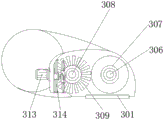
FIG. 2 is a schematic side sectional view of the present invention;
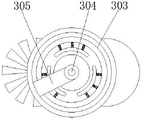
fig. 3 is a schematic view of the structure of the present invention for matching the main shaft with the first rotating shaft and the second rotating shaft;
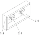
FIG. 4 is a schematic view of the structure of the present invention showing the mutual cooperation between the motor and the fan;
the reference numbers in the figures: 1. a main body; 2. a dust-proof sealing cover; 3. a cleaning mechanism; 301. a suction inlet; 302. a knob; 303. a fixing sheet; 304. a main shaft; 305. rotating the sheet; 306. a first rotating shaft; 307. a dust-collecting drum; 308. a second rotating shaft; 309. a brush; 310. a switch connection sheet; 311. a slide rod; 312. a slider; 313. a motor; 314. a fixed mount; 315. a third rotating shaft; 316. and (6) fanning the sheet.
Detailed Description
The technical solutions in the embodiments of the present invention will be clearly and completely described below with reference to the drawings in the embodiments of the present invention, and it is obvious that the described embodiments are only some embodiments of the present invention, not all embodiments; based on the embodiments in the present invention, all other embodiments obtained by a person skilled in the art without creative efforts all belong to the protection scope of the present invention.
Further, given by fig. 1-4, the utility model provides a technical solution: the utility model provides a dust deposition structure is prevented to dust catcher ground brush, including main part 1 and wiper mechanism 3, dustproof sealing cover 2 is installed in the outside of main part 1, dustproof sealing cover 2's bottom is connected with wiper mechanism 3, wiper mechanism 3 includes suction inlet 301, knob 302, the stationary blade 303, the total axle 304, rotor 305, first rotor 306, dust absorption rotary drum 307, second rotor 308, brush 309, switch connection piece 310, litter 311, slider 312, motor 313, mount 314, third rotor 315 and fan 316, the lower extreme of main part 1 is connected with suction inlet 301, the external connection of main part 1 has knob 302, the inboard of knob 302 is connected with stationary blade 303.
Further, be connected for the draw-in groove between main part 1 and the dustproof sealing lid 2, main part 1 and 2 size phase-matchs of dustproof sealing lid, it is inboard at first to prevent the dust entering in the outside through dustproof sealing lid 2.
Further, the total shaft 304 is installed to the inboard of stationary blade 303, the outside of total shaft 304 is connected with rotor 305, the inboard of rotor 305 is connected with first pivot 306, dust absorption rotary drum 307 is installed to the outside of first pivot 306, one side of first pivot 306 is provided with second pivot 308, the outside of second pivot 308 is connected with brush 309, it is rotatory to drive first pivot 306 and second pivot 308 through total shaft 304 and cooperate each other, can increase the dust removal dynamics.
Furthermore, the fixing plate 303 is connected with the main shaft 304 through a screw, the fixing plate 303 forms a rotating structure with the rotor plate 305 through the main shaft 304, the inner main shaft 304 rotates by rotating the outer knob 302, and the rotor plate 305 is driven to rotate in the chute of the fixing plate 303 to control the movement of the rotating shaft.
Furthermore, the first rotating shaft 306 is connected with the dust collection rotating cylinder 307 in an adhesion manner, the second rotating shaft 308 is connected with the brush 309 in an adhesion manner, the first rotating shaft 306 and the second rotating shaft 308 rotate in a reciprocal manner, and the dust collection rotating cylinder 307 outside the first rotating shaft 306 and the brush 309 driven by the second rotating shaft 308 rotate in a reciprocal manner and rotate clockwise as a whole under the control of the main shaft 304, so that the interior of the dust collection rotating cylinder is simply dedusted.
Further, a switch connecting sheet 310 is installed outside the main body 1, a sliding rod 311 is arranged inside the switch connecting sheet 310, a sliding block 312 is arranged outside the sliding rod 311, a motor 313 is arranged at one end of the inner side of the main body 1, a fixing frame 314 is installed on one side of the motor 313, a third rotating shaft 315 is connected to the inner side of the fixing frame 314, a fan blade 316 is arranged outside the third rotating shaft 315, the floor brush is placed into water, the motor 313 drives the third rotating shaft 315 to rotate, the outer fan blade 316 rotates to drive water to flow, the inside is integrally cleaned, and dust accumulation is prevented.
Furthermore, the fixing frame 314 is connected with the third rotating shaft 315 through screws, the fixing frame 314 and the fan blades 316 form a rotating structure through the third rotating shaft 315, two sets of the motor 313, the fixing frame 314, the third rotating shaft 315 and the fan blades 316 are arranged, and the momentum of water flow is increased through the rotation of the two sets of rotating fans, so that dead corners are easily cleaned. The vacuum cleaner comprises a suction inlet 301, a knob 302, a fixed plate 303, a general shaft 304, a rotating plate 305, a first rotating shaft 306, a dust collection rotating drum 307, a second rotating shaft 308, a brush 309, a switch connecting piece 310, a slide rod 311, a slide block 312, a motor 313, a fixed frame 314, a third rotating shaft 315 and a fan blade 316.
The working principle is as follows: for a dust-deposition-preventing structure of a dust collector floor brush, when the dust collector needs to be cleaned, after the dust collector is used for a period of time in the first step, dust enters the inside of the dust collector through a suction inlet 301, the outer side of the dust collector rotates, 302 enables an inner side main shaft 304 to rotate, a rotating sheet 305 is driven to rotate in a sliding groove in a fixed sheet 303, the dust collector is enabled to rotate in a sliding groove in a rotating manner when a dust collection rotating drum 307 on the outer side of a first rotating shaft 306 and a brush 309 driven by a second rotating shaft 308 rotate in a mutually reverse direction, the whole dust collector wholly rotates clockwise, the inside of the dust collector is simply cleaned, then a switch is clamped through a sliding block 312 on the outer side, a dustproof sealing cover 2 is opened, the floor brush is placed into water, a motor 313 drives a third rotating shaft 315 to rotate, a fan blade 316 on the outer side rotates to drive water to rotate, the inside of the dust collector is wholly cleaned, dust deposition is prevented, the working efficiency is improved, and the using process of the dust-deposition-preventing structure of the dust collector floor brush is completed.
It is noted that, herein, relational terms such as first and second, and the like may be used solely to distinguish one entity or action from another entity or action without necessarily requiring or implying any actual such relationship or order between such entities or actions. Also, the terms "comprises," "comprising," or any other variation thereof, are intended to cover a non-exclusive inclusion, such that a process, method, article, or apparatus that comprises a list of elements does not include only those elements but may include other elements not expressly listed or inherent to such process, method, article, or apparatus.
Although embodiments of the present invention have been shown and described, it will be appreciated by those skilled in the art that various changes, modifications, substitutions and alterations can be made in these embodiments without departing from the principles and spirit of the invention, the scope of which is defined in the appended claims and their equivalents.
Claims (7)
1. The utility model provides a dust accumulation structure is prevented to dust catcher scrubbing brush, includes main part (1) and wiper mechanism (3), its characterized in that: dustproof sealing lid (2) are installed in the outside of main part (1), the bottom of dustproof sealing lid (2) is connected with wiper mechanism (3), wiper mechanism (3) are including sunction inlet (301), knob (302), stationary blade (303), total axle (304), rotor (305), first pivot (306), dust absorption rotary drum (307), second pivot (308), brush (309), switch connection piece (310), litter (311), slider (312), motor (313), mount (314), third pivot (315) and fan piece (316), the lower extreme of main part (1) is connected with sunction inlet (301), the external connection of main part (1) has knob (302), the inboard of knob (302) is connected with stationary blade (303).
2. The dust-deposition preventing structure of the dust collector floor brush according to claim 1, wherein the main body (1) is connected with the dust-proof sealing cover (2) through a clamping groove, and the size of the main body (1) is matched with that of the dust-proof sealing cover (2).
3. The dust deposition preventing structure of a floor brush of a dust collector according to claim 1, wherein a main shaft (304) is installed at the inner side of the fixed plate (303), a rotating plate (305) is connected to the outer side of the main shaft (304), a first rotating shaft (306) is connected to the inner side of the rotating plate (305), a dust collecting drum (307) is installed at the outer side of the first rotating shaft (306), a second rotating shaft (308) is arranged at one side of the first rotating shaft (306), and a brush (309) is connected to the outer side of the second rotating shaft (308).
4. The dust-deposition preventing structure of the floor brush of the dust collector as claimed in claim 3, wherein the fixing plate (303) is connected with the general shaft (304) by a screw, and the fixing plate (303) forms a rotating structure with the rotating plate (305) through the general shaft (304).
5. The dust-deposition preventing structure of the floor brush of the vacuum cleaner as claimed in claim 3, wherein the first rotating shaft (306) is connected with the dust-collecting drum (307) in an adhesion manner, the second rotating shaft (308) is connected with the brush (309) in an adhesion manner, and the first rotating shaft (306) and the second rotating shaft (308) rotate in opposite directions.
6. The dust deposition preventing structure of the dust collector floor brush according to claim 1, wherein a switch connecting piece (310) is installed outside the main body (1), a sliding rod (311) is arranged inside the switch connecting piece (310), a sliding block (312) is arranged outside the sliding rod (311), a motor (313) is arranged at one end of the inner side of the main body (1), a fixing frame (314) is installed at one side of the motor (313), a third rotating shaft (315) is connected to the inner side of the fixing frame (314), and a fan blade (316) is arranged outside the third rotating shaft (315).
7. The dust deposition preventing structure of the floor brush of the vacuum cleaner as claimed in claim 6, wherein the fixing frame (314) is connected with the third rotating shaft (315) by screws, the fixing frame (314) forms a rotating structure with the fan blades (316) through the third rotating shaft (315), and the motor (313), the fixing frame (314), the third rotating shaft (315) and the fan blades (316) are provided with two sets.
Priority Applications (1)
| Application Number | Priority Date | Filing Date | Title |
|---|---|---|---|
| CN202222902412.7U CN218606364U (en) | 2022-11-02 | 2022-11-02 | Dust accumulation preventing structure of dust collector floor brush |
Applications Claiming Priority (1)
| Application Number | Priority Date | Filing Date | Title |
|---|---|---|---|
| CN202222902412.7U CN218606364U (en) | 2022-11-02 | 2022-11-02 | Dust accumulation preventing structure of dust collector floor brush |
Publications (1)
| Publication Number | Publication Date |
|---|---|
| CN218606364U true CN218606364U (en) | 2023-03-14 |
Family
ID=85474848
Family Applications (1)
| Application Number | Title | Priority Date | Filing Date |
|---|---|---|---|
| CN202222902412.7U Active CN218606364U (en) | 2022-11-02 | 2022-11-02 | Dust accumulation preventing structure of dust collector floor brush |
Country Status (1)
| Country | Link |
|---|---|
| CN (1) | CN218606364U (en) |
-
2022
- 2022-11-02 CN CN202222902412.7U patent/CN218606364U/en active Active
Similar Documents
| Publication | Publication Date | Title |
|---|---|---|
| CN102920395A (en) | Double-side self-cleaning linkage structure for filter cartridge of dust collector | |
| CN218655626U (en) | A intelligent cleaning device for photovoltaic solar panel | |
| CN215078059U (en) | Double-suction-port floor sweeping robot | |
| CN215805325U (en) | Fan capable of preventing dust from gathering | |
| CN218358088U (en) | Coal dust collector | |
| CN214486111U (en) | Environment-friendly dust removal and filtration device | |
| CN223126417U (en) | A self-cleaning combing filter structure for a vacuum cleaner | |
| CN113684620A (en) | Air suction device of sewing machine for clothing production | |
| CN218763889U (en) | Inner cleaning device for fan coil pipe | |
| CN201776043U (en) | Self-cleaning air filter apparatus | |
| CN217018865U (en) | Adjustable cutting machine for building material detection | |
| CN212941923U (en) | Improved environment-friendly dust collector capable of improving filtering effect | |
| CN213889243U (en) | A sweeps cleaning device for mechanical equipment | |
| CN117065481A (en) | Air compressor based on self-rotation automatic cleaning filter element dust | |
| CN214284745U (en) | Self-cleaning dust collecting device for dust collector | |
| CN213940602U (en) | Handheld energy-saving dust collector | |
| CN217699636U (en) | Cyclone separator | |
| CN212608110U (en) | Powder material dust recovery device | |
| CN210931164U (en) | Dust collecting box for dust collector | |
| CN213316753U (en) | A kind of anti-dust adsorption device for impeller dust collector | |
| CN210079059U (en) | An automatic cleaning dust bag type dust removal device | |
| CN112896993A (en) | A clean dust removal all-in-one for belt conveyor | |
| CN218166315U (en) | Silica gel production dust recovery device | |
| CN221209316U (en) | Powder recovery device | |
| CN222422796U (en) | A power cabinet with built-in dust removal structure |
Legal Events
| Date | Code | Title | Description |
|---|---|---|---|
| GR01 | Patent grant | ||
| GR01 | Patent grant |