CN218600215U - Drying mechanism for cloth processing - Google Patents
Drying mechanism for cloth processing Download PDFInfo
- Publication number
- CN218600215U CN218600215U CN202222372312.8U CN202222372312U CN218600215U CN 218600215 U CN218600215 U CN 218600215U CN 202222372312 U CN202222372312 U CN 202222372312U CN 218600215 U CN218600215 U CN 218600215U
- Authority
- CN
- China
- Prior art keywords
- drying
- drying mechanism
- main body
- drying chamber
- roller
- Prior art date
- Legal status (The legal status is an assumption and is not a legal conclusion. Google has not performed a legal analysis and makes no representation as to the accuracy of the status listed.)
- Active
Links
Images



Landscapes
- Drying Of Solid Materials (AREA)
Abstract
本实用新型涉及布料加工设备技术领域,具体公开了一种布料加工用烘干机构,包括烘干机构主体和连接在烘干机构主体顶部的除湿箱,烘干机构主体一侧设有进料口,另一侧设有出料口;烘干机构主体内通过隔板分隔成烘干腔A和烘干腔B,烘干腔A内设有进料辊,烘干腔B内设有出料辊,烘干腔A和烘干腔B底部均设有支撑辊,隔板顶部两侧均设有输送辊;烘干腔A内壁安装加热件;本实用新型中加热件能产生热量,烘干腔A内的含有水分的热气进入除湿箱内脱除部分水,能经风机和送风管送至进风罩内,干燥热风能进入烘干腔B内,对布料进一步烘干,烘干腔B的热风能经过循环口进入烘干腔A内循环。
The utility model relates to the technical field of cloth processing equipment, and specifically discloses a drying mechanism for cloth processing, which comprises a main body of the drying mechanism and a dehumidification box connected to the top of the main body of the drying mechanism. One side of the main body of the drying mechanism is provided with a feeding port , the other side is provided with a discharge port; the main body of the drying mechanism is divided into a drying chamber A and a drying chamber B by a partition, the drying chamber A is provided with a feed roller, and the drying chamber B is provided with a discharge There are support rollers at the bottom of drying chamber A and drying chamber B, and conveying rollers are provided on both sides of the top of the partition; a heating element is installed on the inner wall of drying chamber A; the heating element in the utility model can generate heat, and the drying The hot air containing moisture in the chamber A enters the dehumidification box to remove part of the water, and can be sent to the air inlet hood through the fan and the air supply pipe, and the dry hot air can enter the drying chamber B to further dry the cloth. The hot air from B enters the drying chamber A through the circulation port for circulation.
Description
技术领域technical field
本实用新型涉及布料加工设备技术领域,具体是一种布料加工用烘干机构。The utility model relates to the technical field of cloth processing equipment, in particular to a drying mechanism for cloth processing.
背景技术Background technique
布料加工时会设置多个机构,退浆机构、染色机构、烘干机构、定型机构等,烘干机构能对潮湿的布料进行烘干,布料烘干时,通常由输送辊输送,在输送中采用热风烘干。Multiple mechanisms are set up during fabric processing, such as desizing mechanism, dyeing mechanism, drying mechanism, setting mechanism, etc. The drying mechanism can dry the wet cloth. Tumble dry with hot air.
现有专利公告号为CN216473955U公开的一种化纤布料加工用浆丝机烘干机构中,过将物料的一侧沿着活动杆移出的缺口卡入第一齿轮、第三齿轮连接的压辊之间,绕过两个限位杆至第一齿轮与第二齿轮连接的压辊之间,使物料呈环形分布在主体的内部,第一齿轮、第三齿轮转动将带动与其连接的压辊转动,对物料上的水分进行挤压,减少物料的水分,进入主体的内部通过烘干机对物料进行烘干处理,使烘干之后的物料通过第二齿轮、第一齿轮连接的压辊之间移出,增加了物料在主体内部的时间,提高了烘干的效率。The existing patent notification number is CN216473955U, which discloses a drying mechanism of a sizing machine for chemical fiber cloth processing, through which one side of the material is moved out along the movable rod and snapped into the pressure roller connected by the first gear and the third gear. Between the two limit rods, the material is distributed in the inside of the main body in a ring shape, and the rotation of the first gear and the third gear will drive the rotation of the pressure roller connected to the first gear and the second gear. , squeeze the moisture on the material, reduce the moisture of the material, enter the interior of the main body and dry the material through the dryer, so that the dried material passes between the pressure rollers connected by the second gear and the first gear Moving out increases the time of the material inside the main body and improves the drying efficiency.
上述烘干机构总的布料虽然在主体内部行走路程增加,但布料处于上下相对称的状态,布料烘干时的热气中含有水分,易对出料处的布料产生影响,影响烘干效率。针对以上问题,提出一种布料加工用烘干机构。Although the total cloth of the above-mentioned drying mechanism increases the travel distance inside the main body, the cloth is in a symmetrical state up and down, and the hot air when the cloth is dried contains moisture, which is easy to affect the cloth at the outlet and affect the drying efficiency. In view of the above problems, a drying mechanism for cloth processing is proposed.
实用新型内容Utility model content
本实用新型的目的在于提供一种布料加工用烘干机构,以解决上述背景技术中提出的问题。The purpose of this utility model is to provide a drying mechanism for cloth processing to solve the problems raised in the above-mentioned background technology.
为实现上述目的,本实用新型提供如下技术方案:In order to achieve the above object, the utility model provides the following technical solutions:
一种布料加工用烘干机构,包括烘干机构主体和连接在烘干机构主体顶部的除湿箱,所述烘干机构主体一侧设有进料口,另一侧设有出料口;A drying mechanism for cloth processing, comprising a main body of the drying mechanism and a dehumidification box connected to the top of the main body of the drying mechanism, one side of the main body of the drying mechanism is provided with a material inlet, and the other side is provided with a material outlet;
所述烘干机构主体内通过隔板分隔成烘干腔A和烘干腔B,烘干腔A内设有进料辊,烘干腔B内设有出料辊,烘干腔A和烘干腔B底部均设有支撑辊,所述隔板顶部两侧均设有输送辊;The main body of the drying mechanism is divided into a drying chamber A and a drying chamber B by a partition. The drying chamber A is provided with a feed roller, and the drying chamber B is provided with a discharge roller. The drying chamber A and the drying chamber There are supporting rollers at the bottom of the dry chamber B, and conveying rollers are arranged on both sides of the top of the partition;
所述烘干腔A内壁安装加热件,烘干腔A顶部设有与除湿箱连通的排风口,所述除湿箱内设有若干个交错设置的斜板,所述除湿箱出风端通过管路连接风机,所述风机出风端通过送风管连接进风罩,所述进风罩底部出风口置于烘干腔B内部,所述隔板上设有连通烘干腔A和烘干腔B的循环口。The inner wall of the drying chamber A is equipped with a heating element, and the top of the drying chamber A is provided with an air outlet connected to the dehumidification box. The dehumidification box is provided with several staggered inclined plates, and the air outlet of the dehumidification box passes through The pipeline is connected to the fan, and the air outlet end of the fan is connected to the air inlet hood through the air supply pipe. The air outlet at the bottom of the air inlet hood is placed inside the drying chamber B, and the partition plate is provided with the drying chamber A and the drying chamber. Circulation port of dry chamber B.
在一种可选方案中:所述斜板靠近排风口一侧设有安装在除湿箱内的挡板,所述斜板远离挡板的一侧设有安装在除湿箱内的吸附垫。In an optional solution: the side of the inclined plate close to the air outlet is provided with a baffle installed in the dehumidification box, and the side of the inclined plate away from the baffle is provided with an adsorption pad installed in the dehumidification box.
在一种可选方案中:所述除湿箱一侧连接有用于排出除湿箱内腔底部水的排水管。In an optional solution: one side of the dehumidification box is connected with a drainage pipe for draining water from the bottom of the inner chamber of the dehumidification box.
在一种可选方案中:所述隔板顶部设有用于布料通过的连通口,所述隔板靠近连通口处转动连接辅助辊。In an optional solution: the top of the partition is provided with a communication port for the cloth to pass through, and the partition near the communication port is rotatably connected to the auxiliary roller.
在一种可选方案中:所述进料辊、支撑辊、输送辊和出料辊轴端均连接支撑轴,烘干机构主体内壁设有与支撑轴配合的轴座,所述烘干机构主体外壁连接有用于驱动支撑轴转动的驱动件。In an optional solution: the shaft ends of the feed roller, the support roller, the delivery roller and the discharge roller are all connected to the support shaft, the inner wall of the main body of the drying mechanism is provided with a shaft seat that matches the support shaft, and the drying mechanism The outer wall of the main body is connected with a driving member for driving the rotation of the support shaft.
在一种可选方案中:所述进风罩底部设有若干出风孔,进风罩内腔安装有电热管。In an optional solution: several air outlet holes are provided at the bottom of the air inlet hood, and electric heating pipes are installed in the inner cavity of the air inlet hood.
在一种可选方案中:所述进料辊位置与进料口对应,所述出料辊位置与出料口对应。In an optional solution: the position of the feed roller corresponds to the feed port, and the position of the discharge roller corresponds to the discharge port.
与现有技术相比,本实用新型的有益效果是:Compared with the prior art, the beneficial effects of the utility model are:
本实用新型中加热件能产生热量,烘干腔A内的含有水分的热气进入除湿箱内脱除部分水,能经风机和送风管送至进风罩内,干燥热风能进入烘干腔B内,对布料进一步烘干,烘干腔B的热风能经过循环口进入烘干腔A内循环;In the utility model, the heating element can generate heat, and the hot air containing moisture in the drying chamber A enters the dehumidification box to remove part of the water, and can be sent to the air inlet hood through the fan and the air supply pipe, and the hot dry air can enter the drying chamber In B, the cloth is further dried, and the hot air in drying chamber B enters the drying chamber A through the circulation port for circulation;
本实用新型中布料能经过烘干腔A和烘干腔B烘干后输出,在烘干腔A和烘干腔B内行程均呈V型,增加布料在烘干腔A和烘干腔B内行程,延长烘干时间。In the utility model, the cloth can be output after being dried in the drying chamber A and the drying chamber B, and the strokes in the drying chamber A and the drying chamber B are both V-shaped, increasing the speed of the cloth in the drying chamber A and drying chamber B. Inner stroke for longer drying time.
附图说明Description of drawings
图1为本实用新型的结构示意图。Fig. 1 is the structural representation of the utility model.
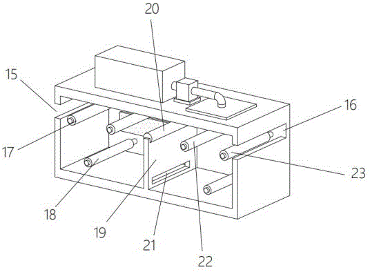
图2为本实用新型中烘干机构主体内部的结构示意图。Fig. 2 is a schematic diagram of the internal structure of the main body of the drying mechanism in the utility model.
图3为本实用新型中布料输送的结构示意图。Fig. 3 is a structural schematic diagram of cloth conveying in the utility model.
图4为本实用新型中除湿箱内部的结构示意图。Fig. 4 is a schematic structural diagram of the interior of the dehumidification box in the present invention.
图中:11、烘干机构主体;12、除湿箱;13、风机;14、送风管;15、进料口;16、出料口;17、进料辊;18、支撑辊;19、隔板;20、辅助辊;21、循环口;22、输送辊;23、出料辊;24、进风罩;25、加热件;26、排风口;27、挡板;28、斜板;29、吸附垫。In the figure: 11, main body of drying mechanism; 12, dehumidification box; 13, fan; 14, air supply pipe; 15, feed inlet; 16, discharge outlet; 17, feed roller; 18, support roller; 19, Partition plate; 20, auxiliary roller; 21, circulation port; 22, conveying roller; 23, discharge roller; 24, air inlet hood; 25, heating element; 26, exhaust port; 29. Adsorption pad.
具体实施方式Detailed ways
请参阅图1-图4,本实施例中,一种布料加工用烘干机构,包括烘干机构主体11和连接在烘干机构主体11顶部的除湿箱12,所述烘干机构主体11一侧设有进料口15,另一侧设有出料口16,进料口15用于待烘干布料的输入,出料口16用于烘干后布料的输出;Please refer to Fig. 1-Fig. 4, in the present embodiment, a drying mechanism for fabric processing includes a drying mechanism
所述烘干机构主体11内通过隔板19分隔成烘干腔A和烘干腔B,烘干腔A内设有进料辊17,烘干腔B内设有出料辊23,烘干腔A和烘干腔B底部均设有支撑辊18,所述隔板19顶部两侧均设有输送辊22,布料在进料辊17、支撑辊18、输送辊22和出料辊23上的输送如图3所示;The
如图3所示,所述烘干腔A内壁安装加热件25,加热件25可为多个电加热管,烘干腔A顶部设有与除湿箱12连通的排风口26,所述除湿箱12内设有若干个交错设置的斜板28,所述除湿箱12出风端通过管路连接风机13,所述风机13出风端通过送风管14连接进风罩24,所述进风罩24底部出风口置于烘干腔B内部,所述隔板19上设有连通烘干腔A和烘干腔B的循环口21;As shown in Figure 3, a
风机13工作,烘干腔A内含有水分的热气能从排风口26进入除湿箱12内,含有水分的热气经过斜板28,部分水凝结在斜板28上滴落至除湿箱12底部,之后除湿的热气经过风机13和送风管14进入进风罩24内,排至烘干腔B内部,对布料进一步烘干,烘干腔B的热风能经过循环口21进入烘干腔A内循环;When the
在本实施例中,布料从进料口15输入,经过进料辊17顶部、支撑辊18底部、输送辊22顶部,输送至烘干腔B内,之后在烘干腔B内,经过输送辊22顶部、支撑辊18底部、出料辊23顶部,加热件25能产生热量对布料烘干,风机13工作,烘干腔A内含有水分的热气能从排风口26进入除湿箱12内,含有水分的热气经过斜板28,部分水凝结在斜板28上滴落至除湿箱12底部,之后除湿的热气经过风机13和送风管14进入进风罩24内,排至烘干腔B内部,对布料进一步烘干,烘干腔B的热风能经过循环口21进入烘干腔A内循环。In this embodiment, the cloth is input from the
在一个实施例中,如图4所示,所述斜板28靠近排风口26一侧设有安装在除湿箱12内的挡板27,含有水分的热气经过斜板28,部分水凝结在斜板28上滴落至除湿箱12底部,所述斜板28远离挡板27的一侧设有安装在除湿箱12内的吸附垫29,吸附垫29可为活性炭板或填充有吸湿剂的板。In one embodiment, as shown in FIG. 4 , the
在一个实施例中,所述除湿箱12一侧连接有用于排出除湿箱12内腔底部水的排水管,凝结的水能滴落在除湿箱12底部,排水管可连接外部管路。In one embodiment, one side of the
在一个实施例中,所述隔板19顶部设有用于布料通过的连通口,所述隔板19靠近连通口处转动连接辅助辊20。In one embodiment, the top of the
在一个实施例中,如图2所示,所述进料辊17、支撑辊18、输送辊22和出料辊23轴端均连接支撑轴,烘干机构主体11内壁设有与支撑轴配合的轴座,所述烘干机构主体11外壁连接有用于驱动支撑轴转动的驱动件,驱动件可为现有的减速电机。In one embodiment, as shown in Figure 2, the shaft ends of the
在一个实施例中,所述进风罩24底部设有若干出风孔,进风罩24内腔安装有电热管,进入进风罩24的热风能经过电热管再次加热。In one embodiment, the bottom of the
在一个实施例中,如图2所示,所述进料辊17位置与进料口15对应,所述出料辊23位置与出料口16对应,方便布料的输入和输出。In one embodiment, as shown in FIG. 2 , the position of the
本实用新型使用时,布料从进料口15输入,经过进料辊17顶部、支撑辊18底部、输送辊22顶部,输送至烘干腔B内,之后在烘干腔B内,经过输送辊22顶部、支撑辊18底部、出料辊23顶部,加热件25能产生热量对布料烘干,风机13工作,烘干腔A内含有水分的热气能从排风口26进入除湿箱12内,含有水分的热气经过斜板28,部分水凝结在斜板28上滴落至除湿箱12底部,之后除湿的热气经过风机13和送风管14进入进风罩24内,排至烘干腔B内部,对布料进一步烘干,烘干腔B的热风能经过循环口21进入烘干腔A内循环,在烘干腔A和烘干腔B内行程均呈V型,增加布料在烘干腔A和烘干腔B内行程,延长烘干时间。When the utility model is in use, the cloth is input from the
Claims (7)
Priority Applications (1)
| Application Number | Priority Date | Filing Date | Title |
|---|---|---|---|
| CN202222372312.8U CN218600215U (en) | 2022-09-07 | 2022-09-07 | Drying mechanism for cloth processing |
Applications Claiming Priority (1)
| Application Number | Priority Date | Filing Date | Title |
|---|---|---|---|
| CN202222372312.8U CN218600215U (en) | 2022-09-07 | 2022-09-07 | Drying mechanism for cloth processing |
Publications (1)
| Publication Number | Publication Date |
|---|---|
| CN218600215U true CN218600215U (en) | 2023-03-10 |
Family
ID=85399040
Family Applications (1)
| Application Number | Title | Priority Date | Filing Date |
|---|---|---|---|
| CN202222372312.8U Active CN218600215U (en) | 2022-09-07 | 2022-09-07 | Drying mechanism for cloth processing |
Country Status (1)
| Country | Link |
|---|---|
| CN (1) | CN218600215U (en) |
Cited By (1)
| Publication number | Priority date | Publication date | Assignee | Title |
|---|---|---|---|---|
| CN121576768A (en) * | 2026-01-20 | 2026-02-27 | 泉州佰霖新材料科技有限公司 | Breathable leather-feel coated mesh drying equipment |
-
2022
- 2022-09-07 CN CN202222372312.8U patent/CN218600215U/en active Active
Cited By (2)
| Publication number | Priority date | Publication date | Assignee | Title |
|---|---|---|---|---|
| CN121576768A (en) * | 2026-01-20 | 2026-02-27 | 泉州佰霖新材料科技有限公司 | Breathable leather-feel coated mesh drying equipment |
| CN121576768B (en) * | 2026-01-20 | 2026-05-08 | 泉州佰霖新材料科技有限公司 | Breathable leather-feel coated mesh drying equipment |
Similar Documents
| Publication | Publication Date | Title |
|---|---|---|
| CN111156808A (en) | A drying device for textiles | |
| CN112797771B (en) | A uniform drying device for textile and garment production | |
| CN209726719U (en) | Cloth drying device for textile and garment | |
| CN212512356U (en) | A drying device for food processing | |
| CN207313920U (en) | A kind of Novel cloth dryer | |
| CN211120520U (en) | A multi-layer mesh belt dryer | |
| CN212582204U (en) | Non-woven fabric production setting device for gauze mask | |
| CN210975216U (en) | Automatic drying and preshrinking machine | |
| CN211041718U (en) | Textile oven | |
| CN117188072B (en) | Water wave crepe drying device | |
| CN216011610U (en) | Drying device for spinning | |
| CN216245383U (en) | A kind of drying equipment for clothing textile fabrics | |
| CN111457704A (en) | Textile cloth drying machine capable of efficiently drying | |
| CN214747108U (en) | Rotary screen dryer | |
| CN210740987U (en) | Drying device for textile machinery | |
| CN202786854U (en) | Clothes dryer | |
| CN224065838U (en) | Cloth drying device | |
| CN222761303U (en) | Cloth drying device | |
| CN214782632U (en) | A drying and ironing device for textile fabrics | |
| CN219064044U (en) | Drying device is used in non-woven fabrics production | |
| CN221924422U (en) | Efficient setting machine drying structure | |
| CN112033109A (en) | Novel drum-type continuous drying equipment | |
| CN217651445U (en) | Improved fabric setting machine | |
| CN221859132U (en) | Drying device for fiber material preparation | |
| CN219913825U (en) | Environment-friendly clothing drying device |
Legal Events
| Date | Code | Title | Description |
|---|---|---|---|
| GR01 | Patent grant | ||
| GR01 | Patent grant | ||
| TR01 | Transfer of patent right | ||
| TR01 | Transfer of patent right |
Effective date of registration: 20251113 Address after: 841000 Xinjiang Uygur Autonomous Region Bayingol Mongolian Autonomous Prefecture Korla City Korla Economic and Technological Development Zone Management Committee Incubation Center Room 326 Patentee after: Xinjiang Futai New Material Co.,Ltd. Country or region after: China Address before: 463700 Biyang County, Henan Province industrial cluster area Patentee before: Henan Yimeng Clothing Co.,Ltd. Country or region before: China |