CN218580503U - Steel truss bridge upper chord maintenance car - Google Patents
Steel truss bridge upper chord maintenance car Download PDFInfo
- Publication number
- CN218580503U CN218580503U CN202221849949.5U CN202221849949U CN218580503U CN 218580503 U CN218580503 U CN 218580503U CN 202221849949 U CN202221849949 U CN 202221849949U CN 218580503 U CN218580503 U CN 218580503U
- Authority
- CN
- China
- Prior art keywords
- driving
- cart
- trolley
- bridge
- fixed
- Prior art date
- Legal status (The legal status is an assumption and is not a legal conclusion. Google has not performed a legal analysis and makes no representation as to the accuracy of the status listed.)
- Active
Links
- 229910000831 Steel Inorganic materials 0.000 title claims abstract description 56
- 239000010959 steel Substances 0.000 title claims abstract description 56
- 238000012423 maintenance Methods 0.000 title claims abstract description 33
- 230000007246 mechanism Effects 0.000 claims abstract description 53
- 230000033001 locomotion Effects 0.000 claims abstract description 33
- 239000003638 chemical reducing agent Substances 0.000 claims description 38
- 238000004804 winding Methods 0.000 claims description 26
- 239000000872 buffer Substances 0.000 claims description 16
- 230000001360 synchronised effect Effects 0.000 claims description 6
- 230000005540 biological transmission Effects 0.000 claims description 5
- 238000007689 inspection Methods 0.000 claims 2
- 230000003028 elevating effect Effects 0.000 abstract description 8
- 238000010276 construction Methods 0.000 abstract description 2
- 230000008439 repair process Effects 0.000 abstract description 2
- 239000000725 suspension Substances 0.000 abstract description 2
- 230000007423 decrease Effects 0.000 abstract 1
- 230000008878 coupling Effects 0.000 description 5
- 238000010168 coupling process Methods 0.000 description 5
- 238000005859 coupling reaction Methods 0.000 description 5
- 230000009467 reduction Effects 0.000 description 5
- 230000009471 action Effects 0.000 description 2
- 238000006243 chemical reaction Methods 0.000 description 1
- 239000011248 coating agent Substances 0.000 description 1
- 238000000576 coating method Methods 0.000 description 1
- 238000005260 corrosion Methods 0.000 description 1
- 238000010586 diagram Methods 0.000 description 1
- 230000005611 electricity Effects 0.000 description 1
- 239000000463 material Substances 0.000 description 1
- 230000000630 rising effect Effects 0.000 description 1
Images


Landscapes
- Bridges Or Land Bridges (AREA)
Abstract
The utility model belongs to the technical field of the large-span bridge construction, especially, relate to a steel truss bridge upper chord maintenance car, its characterized in that is including setting up on the track on truss bridge upper chord girder, and along the longitudinal movement cart of following bridge direction longitudinal movement, set up on the dolly track of longitudinal movement cart, and at perpendicular steel bridge direction lateral shifting's sideslip dolly, set up the elevating system on the sideslip dolly, through the rotary mechanism of wire rope group suspension on elevating system, fix the flexible hanging flower basket on rotary mechanism. The utility model discloses whole tool car can be in the same direction as bridge to longitudinal movement, and the flexible hanging flower basket of liftable can be at the lateral shifting of bridge, but through the outside of sideslip truss bridge in the middle of the landing leg of cart, but the flexible hanging flower basket rotatable direction in decline back can stretch out and draw back the extension again, carries out the maintenance and repair at no dead angle to all positions of whole truss bridge, and the maintainer only once gets into and reachs any one place of bridge to improve work efficiency and reduced working strength.
Description
Technical Field
The utility model belongs to the technical field of the large-span bridge construction, especially, relate to a steel truss bridge last quarter tool car.
Background
The steel truss bridge is widely applied to a large-span bridge, an upper chord steel structure of a bridge body needs to regularly inspect and maintain a fastening bolt, an outer anti-corrosion coating and a bridge body matching component, an upper chord maintenance vehicle of the steel truss bridge is equipment for inspecting and maintaining and is arranged on an upper chord longitudinal beam, and a hanging basket for loading maintenance personnel and maintenance materials needs to move and lift up and down at different longitudinal positions of the bridge, can penetrate into the lower part of the upper chord for maintenance and can be lifted above the upper chord so as to avoid the upper chord structure and not hinder the maintenance vehicle from longitudinally walking; because the upper chord top surface of the bridge is also composed of crossed trusses and the maintenance vehicle needs to have a certain length, when the existing maintenance vehicle descends below the upper chord, the lifting sling of the existing maintenance vehicle is easy to interfere with the upper chord trusses and cannot be closer to the vicinity of the upright post of the steel bridge, so that the area cannot be close to observe and maintain; the existing maintenance vehicle for maintaining and repairing the outside of the bridge is hung on a large truss arm on two sides, and maintenance personnel need to climb to the lower side to repair the bridge, so that the bridge is very inconvenient and low in working efficiency.
Disclosure of Invention
The utility model aims at providing a steel truss bridge last quarter tool car can make the tool car get into any place of bridge and carry out the maintenance operation at no dead angle through the design of this tool car.
The purpose of the utility model is realized by the following technical scheme:
the utility model discloses a steel truss bridge upper chord tool car, its characterized in that is including setting up on the track on the truss bridge upper chord roof beam, and along following bridge direction longitudinal movement's longitudinal movement cart, set up on the dolly track on the last truss girder of this longitudinal movement cart, and at perpendicular steel bridge direction lateral shifting's sideslip dolly, set up the elevating system on this sideslip dolly, hang the rotary mechanism on this elevating system through the wire rope group, fix the flexible hanging flower basket on this rotary mechanism.
The longitudinal movement cart comprises a double-upright-column portal frame, an upper truss girder, a portal lower beam, a trolley track and a cart driving device, wherein the trolley track is arranged on the upper truss girder, and the truss girder extends outwards for a section of length from two sides of the double-upright-column portal frame.
The cart drive arrangement include a pair of initiative wheelset, a pair of passive wheelset, drive reduction gear, cart driving motor, four cart clamping rail ware, four cart buffers and wheelset bearing box, a pair of initiative wheelset and a pair of passive wheelset pass through respectively the wheelset bearing box fix the portal bottom end rail on, drive reduction gear suit the epaxial of a pair of action wheelset, cart driving motor set up the high-speed end of drive reduction gear, four cart clamping rail ware and four cart buffers install respectively the both ends of portal bottom end rail, be equipped with manual rocking wheel on every cart clamping rail ware, rotate manual rocking wheel will the longitudinal movement cart fix the track on.
Sideslip dolly include dolly frame, dolly initiative wheelset, the driven wheelset of dolly, with the trinity motor of drive and four dolly buffers that dolly initiative wheelset is connected, the trinity motor of drive include motor, reduction gear and stopper, the trinity motor of drive with dolly initiative wheelset coaxial, four dolly buffers set up respectively four end departments of dolly frame.
The lifting mechanism comprises a lifting driving assembly, four lifting steel wire ropes and four guiding fixed pulleys, the lifting driving assembly and the guiding fixed pulleys are respectively fixed on a trolley frame of the cross travelling trolley,
the lifting driving assembly comprises a worm gear reducer with double output shafts and double input shafts, two couplers connected with two output shafts of the worm gear reducer, two winding drums connected with the two couplers, a motor and a manual rocking wheel, wherein the motor and the manual rocking wheel are connected with two input shafts of the worm gear reducer respectively, the winding drum shaft ends of the two winding drums are fixed on the base plate through bearing seats, and the motor is provided with a brake release handle.
One ends of the four steel wire ropes are fixed on the two drums according to different winding modes, the other ends of the four steel wire ropes are respectively fixed with the four hoisting points in the rotating mechanism through distribution of the guide fixed pulleys, and synchronous motion of the four steel wire ropes is achieved through rotation of the two drums.
The rotary mechanism comprises a rotary support fixing frame, a rotary support, a driving pinion, a worm gear reducer, a driving motor, a rotary encoder, an encoder gear and an encoder elastic coupler, the rotary mechanism is connected with four steel wire ropes of the lifting mechanism through four lug plates on the rotary support fixing frame, the driving motor and the worm gear reducer are fixed on the rotary support fixing frame, the driving pinion is installed on an output shaft of the worm gear reducer and is in meshing transmission with an inner gear ring of the rotary support, an outer ring of the rotary support is fixed on the rotary support fixing frame through 24 bolts distributed on the circumference, the inner gear ring is fixedly connected with the telescopic hanging basket through 24 bolts distributed on the circumference, the rotary encoder is fixed on the rotary support fixing frame, the encoder gear is connected with the rotary encoder shaft through the encoder elastic coupler, the encoder gear is meshed with the driving pinion, the driving motor drives the driving pinion and drives the inner gear ring to rotate and simultaneously drive the telescopic hanging basket to rotate, the encoder gear is meshed with the inner gear ring gear and transmits an obtained rotation angle signal to the rotary encoder, and the rotation angle control system of the maintenance vehicle controls the rotary mechanism.
The telescopic hanging basket comprises a hanging bracket, a main hanging basket, two left and right telescopic hanging baskets, stay cables and lock pins, wherein a rotary supporting connecting flange plate on the upper portion of the hanging bracket is fixedly connected with an inner gear ring in the rotary mechanism through 24 circumferentially distributed bolts, four stand columns below the hanging bracket are fixedly connected with the main hanging basket through four connecting flanges, the side surfaces of the hanging bracket are connected with the main hanging basket through four stay cables, four idler wheels are respectively arranged on the upper portion and the lower portion of each side surface of each left and right telescopic hanging basket and roll in an upper slideway and a lower slideway of the main hanging basket respectively, and the left and right telescopic hanging baskets are fixed with the main hanging basket through the lock pins.
The utility model has the advantages that:
the utility model discloses a steel truss bridge last quarter tool car, but have a lateral shifting's dolly on the longitudinal movement cart, hang a hanging flower basket that has rotary device below the dolly, there is a scalable hanging flower basket inside again, make whole tool car can be in the same direction as the bridge to longitudinal movement, the flexible hanging flower basket of liftable can be at the lateral shifting of bridge, but the outside of sideslip to truss bridge in the middle of the landing leg through the cart, but the flexible hanging flower basket rotatable direction of back descends, can stretch out and draw back and extend, just so can carry out the maintenance at no dead angle to all positions of whole truss bridge, the maintainer only needs once to get into behind the flexible hanging flower basket and controls equipment through the remote controller, can reach any place of bridge, thereby improve work efficiency and reduced working strength.
Drawings
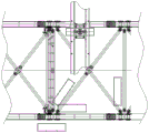
Fig. 1 is a schematic structural diagram of the present invention.
Fig. 2 is an enlarged view of the portion i of fig. 1 according to the present invention.
Fig. 3 is an enlarged view of part ii of fig. 1 according to the present invention.
Fig. 4 is an enlarged view of part iii of fig. 1 according to the present invention.
Fig. 5 is a view of the utility model shown in fig. 1 from direction a.
Fig. 6 is a view of the present invention from direction B of fig. 1.
Figure 7 is the utility model discloses a top view of tool car in different maintenance positions.
Detailed Description
The following description of the embodiments of the present invention will be made with reference to the accompanying drawings.
As shown in fig. 1-7, the utility model discloses a steel truss bridge upper chord maintenance car, its characterized in that is including setting up on the track 7 on truss bridge 6 upper chord roof beam, and along longitudinal movement cart 1 of following the bridge direction longitudinal movement, set up on the dolly track 1.4 on the last truss girder of this longitudinal movement cart 1, and at the sideslip dolly 2 of perpendicular steel bridge direction lateral movement, set up elevating system 3 on this sideslip dolly 2, hang rotary mechanism 4 on this elevating system 3 through wire rope group, fix the telescopic hanging basket 5 on this rotary mechanism 4.
The longitudinal movement cart 1 comprises a double-column portal 1.1, an upper truss girder 1.2, a portal lower beam 1.3, a trolley track 1.4 and a cart driving device, wherein the trolley track 1.4 is installed on the upper truss girder 1.2, and the truss girder 1.2 extends outwards for a length at each of two sides of the double-column portal 1.1.
The cart driving device comprises a pair of driving wheel sets 1.5, a pair of driven wheel sets 1.6, a driving reducer 1.7, a cart driving motor 1.8, four cart rail clamping devices 1.9, four cart buffers 1.10 and a wheel set bearing box 1.11, wherein the driving wheel sets 1.5 and the driven wheel sets 1.6 are respectively fixed on the portal lower beam 1.3 through the wheel set bearing box 1.11, the driving reducer 1.7 is sleeved on the driving wheel sets 1.5, the cart driving motor 1.8 is arranged at the high-speed end of the driving reducer 1.7, the four cart rail clamping devices 1.9 and the four cart buffer devices 1.10 are respectively arranged at the two ends of the portal lower beam 1.3, and each cart rail clamping device 1.9 is provided with a manual rocking wheel 1.9.1, and the manual rocking wheel 1.9.1 is rotated to fix the longitudinal movement cart 1 on the longitudinal movement track 7.
The lifting mechanism 3 comprises a lifting driving assembly, four lifting steel wire ropes 3.11, 3.12, 3.13, 3.14 and four guide fixed pulleys 3.15, the lifting driving assembly and the guide fixed pulleys 3.15 are respectively fixed on a trolley frame 2.1 of the traverse trolley 2,
the lifting driving assembly comprises a worm and gear reducer 3.5, two couplers 3.3 and 3.4 connected with two output shafts of the worm and gear reducer 3.5, two winding drums 3.1 and 3.2 respectively connected with the two couplers, a motor 3.7 and a manual rocking wheel 3.8 respectively connected with two input shafts of the worm and gear reducer 3.5, winding drum shaft ends of the two winding drums 3.1 and 3.2 are fixed on a base plate 3.10 through bearing seats 3.6, the motor 3.7 is provided with a brake release handle 3.9,
one ends of the four steel wire ropes (3.11-3.14) are fixed on the two winding drums 3.1 and 3.2 according to different winding modes, the other ends of the four steel wire ropes are respectively fixed with the four hoisting points in the rotating mechanism 4 through distribution of the guide fixed pulleys 3.15, and synchronous motion of the four steel wire ropes is realized through rotation of the two winding drums 3.1 and 3.2.
The rotating mechanism 4 comprises a rotating support fixing frame 4.1, a rotating support 4.2, a driving pinion 4.3, a worm reducer 4.4, a driving motor 4.5, a rotary encoder 4.6, an encoder gear 4.7 and an encoder elastic coupling 4.8, the rotating mechanism 4 is connected with four steel wire ropes (3.11-3.14) of the lifting mechanism 3 through four lug plates 4.1.1 on the rotating support fixing frame 4.1, the driving motor 4.5 and the worm reducer 4.4 are fixed on the rotating support fixing frame 4.1, the driving pinion 4.3 is arranged on an output shaft of the worm reducer 4.4 and is in meshing transmission with an inner gear ring 4.2.1 of the rotating support 4.2, and an outer ring 4.2.2 of the rotating support is fixed on the rotating support fixing frame 4.1 through 24 circumferentially distributed bolts 4.2.3, the inner gear ring 4.2.1 is fixedly connected with the telescopic hanging basket 5 through 24 circumferentially distributed bolts 4.2.4, the rotary encoder 4.6 is fixed on the rotary support fixing frame 4.1, the encoder gear 4.7 is connected with the rotary encoder 4.6 through an encoder elastic coupling 4.8, the encoder gear 4.7 is meshed with the driving pinion 4.3, the driving motor 4.5 drives the driving pinion 4.3 and the inner gear ring 4.2.1 to rotate and simultaneously drives the telescopic hanging basket 5 to rotate, the encoder gear 4.7 is meshed with the inner gear ring 4.2.1 and transmits an obtained rotation angle signal to the rotary encoder 4.6 to control the rotation angle of the rotary mechanism 4.
The telescopic hanging basket 5 comprises a hanging bracket 5.1, a main hanging basket 5.2, two left and right telescopic hanging baskets 5.3, stay cables 5.4 and lock pins 5.5, wherein a rotary support connecting flange 5.1.1 at the upper part of the hanging bracket 5.1 is fixedly connected with an inner gear ring 4.2.1 in the rotary mechanism 3 through 24 circumferentially distributed bolts 4.2.4, four stand columns below the hanging bracket 5.1 are fixedly connected with the main hanging basket 5.2 through four connecting flanges 5.1.2, the side surface of the hanging bracket 5.1 is connected with the main hanging basket 5.2 through four stay cables 5.4, four rollers 5.3.1 are respectively arranged on the upper surface and the lower surface of each side surface of the left and right telescopic hanging baskets 5.3, the rollers roll in upper and lower slideways 5.2.1 of the main hanging basket 5.2 respectively, and the left and right telescopic hanging baskets 5.3 are fixed with the main hanging baskets 5.2 through the lock pins 5.5.
The utility model discloses a new steel truss bridge last quarter tool car comprises longitudinal movement cart 1, sideslip dolly 2, elevating system 3, rotary mechanism 4, scalable hanging flower basket 5 and control system. The longitudinal movement cart 1 is arranged on a track 7 on an upper chord beam of a truss bridge 6 and can longitudinally move along the direction along the bridge, the transverse moving trolley 2 is arranged on a trolley track 1.4 on the upper truss beam of the longitudinal movement cart 1 and can transversely move in the direction vertical to the steel bridge, the lifting mechanism 3 is arranged on the transverse moving trolley 2 and can enable the rotating mechanism 4 and the telescopic hanging basket 5 to vertically lift up and down, the rotating mechanism 4 is hung on the lifting mechanism 3 through four steel wire ropes, the telescopic hanging basket 5 is fixed on the rotating mechanism 4, the telescopic hanging basket 5 can rotate in the 360-degree direction through the rotating mechanism 4 and can be stretched outwards by itself, and the telescopic hanging basket 5 can reach any place of the steel truss bridge 6 to carry out operation by matching with the movement of the longitudinal movement cart 1 and the transverse moving trolley 2.
The longitudinal movement cart 1 comprises a double-upright-column portal frame 1.1, an upper truss girder 1.2, a portal frame lower beam 1.3, a trolley track 1.4 and a cart driving device (1.5-1.11), wherein the trolley track 1.4 is arranged on the upper truss girder 1.2, the upper truss girder 1.2 extends out a length at two sides of the double-upright-column portal frame 1.1 respectively, the distance between the double-upright-column portal frame 1.1 can ensure that a suspension rotating mechanism 4 and a telescopic hanging basket 5 pass through, and the telescopic hanging basket 5 can move to the outer parts of two sides of a truss bridge 6 through the double-upright-column portal frame 1.1 after rising to the highest position. The cart driving device ((1.5-1.11)) comprises a pair of driving wheel sets 1.5, a pair of driven wheel sets 1.6, a driving reducer 1.7, a cart driving motor 1.8, cart rail clamping devices 1.9, cart buffers 1.10 and a wheel set bearing box 1.11, wherein the driving wheel sets 1.5 and the driven wheel sets 1.6 are respectively fixed on a lower beam 1.3 of a double-upright-column gantry 1.1 through the wheel set bearing boxes 1.11, the driving reducer 1.7 is sleeved on a shaft of the driving wheel sets 1.5, the cart driving motor 1.8 is arranged at a high-speed end of the driving reducer 1.7, the cart driving motor 1.8 has frequency conversion starting and braking functions, the four cart rail clamping devices 1.9 and the four cart buffer devices 1.10 are respectively arranged at two ends of the lower beam 1.3 of the gantry, and the manual swinging wheels 1.9.1 of the rotary cart rail clamping devices 1 can fix the longitudinally moving cart 1 on the cart rail 7 to prevent the cart 1 from being blown away by large wind.
The traversing trolley 2 consists of a trolley frame 2.1, two sets of trolley driving wheel groups 2.2, two sets of trolley driven wheel groups 2.3, a driving three-in-one motor 2.4 connected with the driving wheel groups 2.2 and four trolley buffers 2.5, wherein the driving three-in-one motor 2.4 is coaxial with the trolley driving wheel groups 2.2 and comprises three parts of a motor, a speed reducer and a brake, and the trolley buffers 2.5 are arranged at the ends of the trolley frame 2.1. The transverse trolley 2 can enable the telescopic hanging basket 5 to move transversely and transversely, and can move to the left side and the right side of the truss bridge 6 to be overhauled through the double-upright-column portal frame 1.1 of the longitudinal moving cart 1.
The lifting mechanism 3 consists of a lifting driving assembly (3.1-3.10), four lifting steel wire ropes 3.11, 3.12, 3.13, 3.14 and four guide fixed pulleys 3.15, wherein the lifting driving assembly and the guide fixed pulleys 3.15 are respectively fixed on a trolley frame 2.1 of the transverse trolley 2, one ends of the four steel wire ropes (3.11-3.14) are fixed on two winding drums 3.1 and 3.2 of the lifting driving assembly according to different winding modes, the other ends of the four steel wire ropes are respectively fixed with four hoisting points on a rotary supporting and fixing frame 4.1 in the rotating mechanism 4 through the distribution of the guide fixed pulleys 3.15, and the synchronous motion of the four steel wire ropes is realized through the rotation of the two winding drums 3.1 and 3.2, so that the lifting actions of the rotating mechanism 4 and the telescopic hanging basket 5 are completed. When the maintenance vehicle needs to move, the lifting mechanism 3 lifts the hanging basket 5 to the upper part of the upper chord 6 without hindering the longitudinal movement of the maintenance vehicle.
Two drums 3.1 and 3.2 of a driving assembly are connected with two output shafts of a high-speed ratio worm gear reducer 3.5 through couplings 3.3 and 3.4 respectively to realize synchronous and same-direction rotation of the drums 3.1 and 3.2, drum shaft ends are fixed on a base plate 3.10 through bearing seats 3.6, two input shafts of the reducer 3.5 are connected with a motor 3.7 and a manual rocking wheel 3.8 respectively to realize two driving modes of electric driving and manual driving, the motor 3.7 has a braking function and is provided with a braking release handle 3.9, steel wire ropes 3.11 and 3.12 are wound on the same drum 3.1, the steel wire ropes 3.13 and 3.14 are wound on the other drum 3.2, wherein the steel wire ropes 3.11 and 3.13 are in a downward winding mode, and the steel wire ropes 3.12 and 3.14 are in an upward winding mode. The other ends of the four steel wire ropes are respectively connected to a rotary supporting fixed frame 4.1 through the distribution of four guiding fixed pulleys 3.15 to drive the rotating mechanism 4 and the telescopic hanging basket 5 to lift. The mechanical parts on the driving assembly are respectively fixed on the base plate 3.10 and are fixed with the trolley frame 2.1 of the traverse trolley 2 through the base plate 3.10.
A worm and gear reducer 3.5 in the lifting mechanism 3 is provided with a double input shaft and a double output shaft, two winding drums 3.1 and 3.2 are respectively connected with two output shafts of the worm and gear reducer 3.5, synchronous transmission can be ensured, and two groups of steel wire ropes on the same winding drum are respectively wound up and down, so that when the two winding drums 3.1 and 3.2 rotate in one direction, four steel wire ropes (3.11-3.14) can be simultaneously wound in or simultaneously wound out, and the telescopic hanging basket 5 is synchronously lifted; one input shaft of the worm and gear reducer 3.5 is connected with a motor shaft of a motor 3.7, meanwhile, the other input shaft of the worm and gear reducer 3.5 is provided with a manual rocking wheel 3.8, when the motor 3.7 cannot obtain dynamic electricity, a brake release handle 3.9 on the motor 3.7 is opened, and the telescopic hanging basket 5 can be lifted and descended by manually rotating the manual rocking wheel 3.8.
The rotating mechanism 4 is composed of a rotating support fixing frame 4.1, a rotating support 4.2, a driving pinion 4.3, a worm reducer 4.4, a driving motor 4.5, a rotary encoder 4.6, an encoder gear 4.7 and an encoder elastic coupling 4.8, wherein the rotating mechanism 4 is connected with four steel wire ropes (3.11-3.14) of the lifting mechanism 3 through four lug plates 4.1.1 on the rotating support fixing frame 4.1, the driving motor 4.5 and the worm reducer 4.4 are fixed on the rotating support fixing frame 4.1, the driving pinion 4.3 is arranged on an output shaft of the worm reducer 4.4 and is in meshing transmission with an inner gear ring 4.2.1 of the rotating support 4.2, an outer ring 4.2.2 of the rotating support 4.2 is fixed on the rotating support fixing frame 4.1 through 24 circumferentially distributed bolts 4.2.3, the inner gear ring 4.2.1 of the rotating support 4.2 is also in fixed connection with a telescopic hanging bracket 5.1 through 24 circumferentially distributed bolts 4.2.4, the rotating encoder 4.6 is fixed on the rotating support fixing frame, the rotating support fixing frame 4.1, the rotating encoder 4.8 is also in meshing with the rotating support fixing frame through the elastic coupling 4.4.4, and is in connection with a hanging basket. The driving motor 4.5 drives the driving pinion 4.3 and drives the inner gear ring 4.2.1 of the rotary support 4.2 to rotate, and simultaneously drives the telescopic hanging basket 5 below to rotate, the encoder gear 4.7 is meshed with the inner gear ring 4.2.1 of the rotary support 4.2 and transmits an obtained rotation angle signal to the rotary encoder 4.6, so that the rotation angle of the rotary mechanism 4 is controlled.
The telescopic hanging basket 5 consists of a hanging bracket 5.1, a main hanging basket 5.2, two left and right telescopic hanging baskets 5.3, stay cables 5.4 and a lock pin 5.5, wherein a rotary supporting connecting flange 5.1.1 at the upper part of the hanging bracket 5.1 is fixedly connected with an inner gear ring 4.2.1 in a rotary mechanism through 24 circumferentially distributed bolts 4.2.4, four upright posts below the hanging bracket 5.1 are fixedly connected with the main hanging basket 5.2 through four connecting flanges 5.1.2, the side surface of the hanging bracket 5.1 is also connected with the main hanging basket 5.2 through four stay cables 5.4, so that the stability of the hanging basket 5 is improved, four rollers 5.3.1 are respectively arranged on the upper surface and the lower surface of each side surface of the left and right telescopic hanging baskets 5.3, can respectively roll in upper and lower slideways 5.2.1 of the main hanging basket 5.2, and the left and right telescopic hanging baskets 5.3 are fixed with the main hanging basket 5.2 through the lock pin 5.5.
Longitudinal movement cart driving motor 1.8 of maintenance car, drive trinity motor 2.4, elevating system's motor 3.7, rotary mechanism's driving motor 4.5 all is by PLC bus control, start-up stops to adopt variable frequency speed governing, reduce inertial impulse, it is remote controller control to control the mode, the operating personnel can be controlled each mechanism of whole maintenance car through remote control handle 7 in flexible hanging flower basket 5, need not climb into and climb out like the maintenance car before, and can make the maintenance car get into any place of bridge through the design of this maintenance car and carry out the maintenance operation at no dead angle.
The utility model discloses a steel truss bridge last quarter tool car, but have a lateral shifting's dolly on the longitudinal movement cart, hang a hanging flower basket that has rotary device below the dolly, the hanging flower basket is inside to have a scalable hanging flower basket again, make whole tool car can be in the same direction as the bridge to longitudinal movement, liftable telescopic hanging flower basket 5 can be at the lateral shifting of bridge, but the outside of sideslip to the bridge in the middle of the landing leg through the cart, telescopic hanging flower basket 5 rotatable direction after descending, can stretch out and draw back the extension again, just so can carry out the maintenance at no dead angle to all positions of whole truss bridge, the maintainer only once gets into and controls equipment through the remote controller after telescopic hanging flower basket 5, can reach any place of bridge, thereby improve work efficiency and reduced working strength.
Claims (7)
1. A steel truss bridge upper chord maintenance vehicle is characterized by comprising a longitudinal moving cart, a transverse moving trolley, a lifting mechanism, a rotating mechanism and a telescopic hanging basket, wherein the longitudinal moving cart is arranged on a track on an upper chord beam of a truss bridge and longitudinally moves along the direction along the bridge, the transverse moving trolley is arranged on a trolley track on the upper truss beam of the longitudinal moving cart and transversely moves in the direction vertical to the steel bridge, the lifting mechanism is arranged on the transverse moving trolley, the rotating mechanism is hung on the lifting mechanism through a steel wire rope set, and the telescopic hanging basket is fixed on the rotating mechanism.
2. The steel truss bridge upper chord maintenance vehicle according to claim 1, wherein the longitudinal movement cart comprises a double-column portal frame, an upper truss girder, a portal frame lower beam, a trolley track and a cart driving device, the trolley track is installed on the upper truss girder, and the truss girder extends outwards for a length on each side of the double-column portal frame.
3. The steel truss bridge upper chord maintenance vehicle according to claim 2, wherein the cart driving device comprises a pair of driving wheel sets, a pair of driven wheel sets, a driving reducer, a cart driving motor, four cart rail clamping devices, four cart buffers and a wheel set bearing box, the pair of driving wheel sets and the pair of driven wheel sets are respectively fixed on the lower beam of the gantry through the wheel set bearing box, the driving reducer is sleeved on the pair of driving wheel sets, the cart driving motor is arranged at the high-speed end of the driving reducer, the four cart rail clamping devices and the four cart buffers are respectively arranged at two ends of the lower beam of the gantry, each cart rail clamping device is provided with a manual rocking wheel, and the longitudinal moving cart is fixed on the track by rotating the manual rocking wheel.
4. The steel truss bridge winding inspection vehicle of claim 1, wherein the traverse trolley comprises a trolley frame, a trolley driving wheel set, a trolley driven wheel set, a driving three-in-one motor connected with the trolley driving wheel set and four trolley buffers, the driving three-in-one motor comprises a motor, a speed reducer and a brake, the driving three-in-one motor is coaxial with the trolley driving wheel set, and the four trolley buffers are respectively arranged at four ends of the trolley frame.
5. The steel truss bridge upper chord maintenance car according to claim 1, wherein the lifting mechanism comprises a lifting driving assembly, four lifting steel cables, and four guiding fixed pulleys, the lifting driving assembly and the guiding fixed pulleys are respectively fixed on a trolley frame of the traverse trolley,
the lifting driving assembly comprises a worm gear reducer with double output shafts and double input shafts, two couplers connected with two output shafts of the worm gear reducer, two winding drums respectively connected with the two couplers, and a motor and a manual rocking wheel respectively connected with the two input shafts of the worm gear reducer, wherein the shaft ends of the winding drums of the two winding drums are fixed on a base plate through bearing seats, and the motor is provided with a brake release handle;
one ends of the four steel wire ropes are fixed on the two winding drums according to different winding modes, the other ends of the four steel wire ropes are respectively fixed with the four hoisting points in the rotating mechanism through the distribution of the guide fixed pulleys, and the synchronous motion of the four steel wire ropes is realized through the rotation of the two winding drums.
6. The steel truss bridge winding inspection vehicle according to claim 1, wherein the rotating mechanism comprises a rotating support fixing frame, a rotating support, a driving pinion, a worm gear reducer, a driving motor, a rotary encoder, an encoder gear and an encoder elastic coupler, the rotating mechanism is connected with four steel wire ropes of the lifting mechanism through four lug plates on the rotating support fixing frame, the driving motor and the worm gear reducer are fixed on the rotating support fixing frame, the driving pinion is installed on an output shaft of the worm gear reducer and is in meshing transmission with an inner gear ring of the rotating support, an outer ring of the rotating support is fixed on the rotating support fixing frame through 24 bolts distributed circumferentially, the inner gear ring is fixedly connected with the telescopic hanging basket through 24 bolts distributed circumferentially, the rotary encoder is fixed on the rotating support fixing frame, the encoder gear is connected with the rotary encoder shaft through the encoder elastic coupler, the encoder gear is meshed with the driving pinion, the driving motor of the pinion drives the inner gear ring and drives the telescopic hanging basket to rotate, the encoder gear and the rotary encoder gear are combined with the inner gear ring to transmit a rotation angle signal to the rotary encoder, and the rotating angle control system controls the encoder.
7. The steel truss bridge upper chord maintenance vehicle according to claim 1, wherein the telescopic hanging basket comprises a hanging bracket, a main hanging basket, two left and right telescopic hanging baskets, stay cables and lock pins, a rotary support connecting flange plate at the upper part of the hanging bracket is fixedly connected with an inner gear ring in the rotary mechanism through 24 circumferentially distributed bolts, four upright posts below the hanging bracket are fixedly connected with the main hanging basket through four connecting flanges, the side surface of the hanging bracket is connected with the main hanging basket through four stay cables, each side surface of the left and right telescopic hanging baskets is provided with four rollers at the upper part and the lower part, the rollers roll in upper and lower slideways of the main hanging basket respectively, and the left and right telescopic hanging baskets are fixed with the main hanging basket through the lock pins.
Priority Applications (1)
| Application Number | Priority Date | Filing Date | Title |
|---|---|---|---|
| CN202221849949.5U CN218580503U (en) | 2022-07-19 | 2022-07-19 | Steel truss bridge upper chord maintenance car |
Applications Claiming Priority (1)
| Application Number | Priority Date | Filing Date | Title |
|---|---|---|---|
| CN202221849949.5U CN218580503U (en) | 2022-07-19 | 2022-07-19 | Steel truss bridge upper chord maintenance car |
Publications (1)
| Publication Number | Publication Date |
|---|---|
| CN218580503U true CN218580503U (en) | 2023-03-07 |
Family
ID=85361662
Family Applications (1)
| Application Number | Title | Priority Date | Filing Date |
|---|---|---|---|
| CN202221849949.5U Active CN218580503U (en) | 2022-07-19 | 2022-07-19 | Steel truss bridge upper chord maintenance car |
Country Status (1)
| Country | Link |
|---|---|
| CN (1) | CN218580503U (en) |
Cited By (2)
| Publication number | Priority date | Publication date | Assignee | Title |
|---|---|---|---|---|
| CN114960478A (en) * | 2022-07-19 | 2022-08-30 | 珠海东方重工有限公司 | Steel truss bridge winding inspection vehicle |
| CN116553303A (en) * | 2023-05-05 | 2023-08-08 | 北自所(北京)科技发展股份有限公司 | Glass fiber direct yarn doffing loading equipment |
-
2022
- 2022-07-19 CN CN202221849949.5U patent/CN218580503U/en active Active
Cited By (2)
| Publication number | Priority date | Publication date | Assignee | Title |
|---|---|---|---|---|
| CN114960478A (en) * | 2022-07-19 | 2022-08-30 | 珠海东方重工有限公司 | Steel truss bridge winding inspection vehicle |
| CN116553303A (en) * | 2023-05-05 | 2023-08-08 | 北自所(北京)科技发展股份有限公司 | Glass fiber direct yarn doffing loading equipment |
Similar Documents
| Publication | Publication Date | Title |
|---|---|---|
| CN110359936B (en) | Tunnel prefabricated assembly type track lower structure assembling trolley and control system thereof | |
| CN113202020B (en) | Arch rib maintenance vehicle suitable for inspection of box arch rib | |
| CN216038231U (en) | General gantry crane | |
| CN210457238U (en) | Special crane for tubular pile | |
| CN114960478A (en) | Steel truss bridge winding inspection vehicle | |
| CN214653067U (en) | Upper rotating crane trolley of crane special for steel plant | |
| CN206188229U (en) | Cabin driving running gear | |
| CN215798047U (en) | Special crane for grinding roller | |
| CN216377124U (en) | Steel plate conveying crane | |
| CN104671119A (en) | Hammer type gantry crane for collaborative slipway operation | |
| CN214570231U (en) | High-stability beam lifting machine | |
| CN215405581U (en) | Arch rib maintenance vehicle suitable for box type arch rib inspection | |
| CN215364550U (en) | Overhead traveling crane of corridor erecting machine and corridor erecting machine | |
| CN104591002A (en) | Low-clearance double-beam bridge type crane | |
| CN100515910C (en) | A door-type lifting compound device for vehicle body transportation | |
| CN210944635U (en) | Counterweight lifting energy-saving system of crane | |
| CN202429915U (en) | Large-tonnage lifting hook overhead crane | |
| CN214399568U (en) | Novel beam lifting machine | |
| CN221397005U (en) | Intelligent double-beam crane with double lifting appliances | |
| CN210973638U (en) | Single-girder gantry crane | |
| CN223983367U (en) | An electric hoist track transfer platform for lifting holes in the middle floors of buildings | |
| CN221396996U (en) | High-lift low-clearance bridge crane for wind power cabin | |
| CN100506679C (en) | Multifunctional vehicle body transfer equipment | |
| CN223523126U (en) | A mobile steel support for the construction of foundation pits adjacent to railway tunnel projects | |
| CN221565593U (en) | European crane convenient to installation |
Legal Events
| Date | Code | Title | Description |
|---|---|---|---|
| GR01 | Patent grant | ||
| GR01 | Patent grant | ||
| CP03 | Change of name, title or address | ||
| CP03 | Change of name, title or address |
Address after: 519175 West Side of Xincheng Avenue, Fushan Industrial Zone, Zhuhai City, Guangdong Province (Plant A) Patentee after: Zhuhai Dongfang Heavy Industry Co.,Ltd. Address before: West side of Xincheng Avenue, Fushan Industrial Park, Zhuhai City, Guangdong Province, 519175 (Plant A) Patentee before: EASTERN HEAVY INDUSTRY CO.,LTD.,ZHUHAI |