CN218555327U - Bending die with arc barb structure - Google Patents
Bending die with arc barb structure Download PDFInfo
- Publication number
- CN218555327U CN218555327U CN202222076532.6U CN202222076532U CN218555327U CN 218555327 U CN218555327 U CN 218555327U CN 202222076532 U CN202222076532 U CN 202222076532U CN 218555327 U CN218555327 U CN 218555327U
- Authority
- CN
- China
- Prior art keywords
- barb
- mould
- arc
- guide ring
- bending
- Prior art date
- Legal status (The legal status is an assumption and is not a legal conclusion. Google has not performed a legal analysis and makes no representation as to the accuracy of the status listed.)
- Active
Links
- 238000005452 bending Methods 0.000 title claims abstract description 23
- 239000000463 material Substances 0.000 claims description 5
- 229910000831 Steel Inorganic materials 0.000 claims description 3
- 239000010959 steel Substances 0.000 claims description 3
- 238000010586 diagram Methods 0.000 description 2
- 230000004075 alteration Effects 0.000 description 1
- 230000009286 beneficial effect Effects 0.000 description 1
- 230000007812 deficiency Effects 0.000 description 1
- 238000012986 modification Methods 0.000 description 1
- 230000004048 modification Effects 0.000 description 1
- 230000002035 prolonged effect Effects 0.000 description 1
- 238000005728 strengthening Methods 0.000 description 1
- 238000006467 substitution reaction Methods 0.000 description 1
Images

Landscapes
- Bending Of Plates, Rods, And Pipes (AREA)
Abstract
The utility model aims at solving the deformation problem of barb structure mould of bending, disclose a mould of bending with arc barb structure, including the barb mould, the link is equipped with to barb mould side, the second fastening screw is installed to the symmetry between link and the barb mould, barb mould surface downside is equipped with the guide ring, first fastening screw is installed to the symmetry between guide ring and the barb mould, the inside cover of guide ring has the ejector pin, ejector pin surface downside cover has the nut, be connected with coil spring between nut and the guide ring. The utility model discloses an arc part at the barb mould uses the ejector pin to withstand, and the rethread link is strengthened the barb mould of arc structure, prevents that the barb mould from warping.
Description
Technical Field
The utility model relates to a mould field of bending especially relates to a mould of bending with arc barb structure.
Background
The bending machine die is a tool used by a bending machine for forming and processing a plate material, the tool comprises various parts, and different dies comprise different parts. The processing of the shape of an article is realized mainly by changing the physical state of a formed material, and the processing is used for enabling a blank to be a tool for a workpiece with a specific shape and a specific size under the action of the pressure of a bending machine.
The bending die has various shapes, some are curved and some are columnar, and the die with the barb structure is arranged, but when the die with the barb structure is used, the arc part of the end part can be stressed for a long time, the die can be bent by long-time stamping, and the die can be bent to deform.
SUMMERY OF THE UTILITY MODEL
The utility model aims at solving the deficiency of the prior art and providing a bending die with an arc barb structure.
The utility model discloses a realize through following technical scheme:
the utility model provides a mould of bending with arc barb structure, includes the barb mould, the link is equipped with to barb mould side, the second fastening screw is installed to the symmetry between link and the barb mould, barb mould surface downside is equipped with the guide ring, first fastening screw is installed to the symmetry between guide ring and the barb mould, the inside ejector pin that has overlapped of guide ring, ejector pin surface downside cover has the nut, be connected with coil spring between nut and the guide ring.
As the preferred technical scheme of the utility model, barb mould top is the arc structure.
As the utility model discloses an optimized technical scheme, the link just makes for steel material for U type structure.
As the utility model discloses a preferred technical scheme, the ejector pin is L type structure.
As the utility model discloses a preferred technical scheme, ejector pin and guide ring sliding fit.
As the utility model discloses an optimized technical scheme, screw-thread fit between ejector pin and the nut, coil spring respectively with guide ring and nut fixed connection.
Compared with the prior art, the beneficial effects of the utility model are that:
the utility model discloses a set up the link, the location supporting role to the barb mould has been played, thereby be convenient for strengthen the barb mould, prevent that the barb mould from appearing warping, setting through the ejector pin, can push up the arc constitutional part at the barb mould, the supporting role to barb mould arc constitutional part has been played, the elasticity that rethread coil spring provided, thereby be convenient for promote the ejector pin of L type structure to the arc part of barb mould, the barb mould to the arc structure is strengthened, and then the life of barb mould has been prolonged, it is more durable to make the barb mould. The utility model discloses an arc part at the barb mould uses the ejector pin to withstand, and the rethread link is strengthened the barb mould of arc structure, prevents that the barb mould from warping.
Drawings
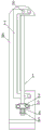
Fig. 1 is a schematic structural diagram of the present invention.
Fig. 2 is a schematic structural diagram of the ejector rod of the present invention.
In the figure: 1. ejector pin, 2, guide ring, 3, first fastening screw, 4, coil spring, 5, nut, 6, barb mould, 7, link, 8, second fastening screw.
Detailed Description
The technical solutions in the embodiments of the present invention will be described clearly and completely with reference to the drawings in the embodiments of the present invention, and it is obvious that the described embodiments are only some embodiments of the present invention, not all embodiments. Based on the embodiments in the present invention, all other embodiments obtained by a person skilled in the art without creative work belong to the protection scope of the present invention.
Referring to fig. 1-2, the present invention provides a technical solution:
the utility model provides a mould of bending with arc barb structure, includes barb mould 6, link 7 is equipped with to 6 sides of barb mould, second fastening screw 8 is installed to the symmetry between link 7 and barb mould 6, 6 surperficial downside of barb mould are equipped with guide ring 2, first fastening screw 3 is installed to the symmetry between guide ring 2 and the barb mould 6, 2 inside covers of guide ring have ejector pin 1, 1 surperficial downside covers of ejector pin has nut 5, be connected with coil spring 4 between nut 5 and the guide ring 2.
The top end of the barb die 6 is of an arc-shaped structure.
The connecting frame 7 is of a U-shaped structure and made of steel materials.
The ejector rod 1 is of an L-shaped structure.
The ejector rod 1 is in sliding fit with the guide ring 2.
The ejector rod 1 is in threaded fit with the screw cap 5, and the spiral spring 4 is fixedly connected with the guide ring 2 and the screw cap 5 respectively.
The working principle is as follows: this barb mould 6 is the last mould of the mould of bending, through the regulation to nut 5, can prop up ejector pin 1 in the arc structure position of the mould of bending, the arc structure part of the mould of bending of fifty percent discount supports the location, simultaneously through the setting of link 7, can strengthen barb mould 6, prevent barb mould 6 and warp, be equivalent to barb mould 6's strengthening rib, through setting ejector pin 1 into L type structure, just more conveniently carry out the top to barb mould 6's arc part, can set up a plurality of ejector pins 1 as required, further strengthen barb mould 6, protect barb mould 6 when bending.
Although embodiments of the present invention have been shown and described, it will be appreciated by those skilled in the art that various changes, modifications, substitutions and alterations can be made in these embodiments without departing from the principles and spirit of the invention, the scope of which is defined in the appended claims and their equivalents.
Claims (6)
1. The utility model provides a mould of bending with arc barb structure, includes barb mould (6), its characterized in that: barb mould (6) side is equipped with link (7), second fastening screw (8) are installed to the symmetry between link (7) and barb mould (6), barb mould (6) surface downside is equipped with guide ring (2), first fastening screw (3) are installed to the symmetry between guide ring (2) and barb mould (6), the inside cover of guide ring (2) has ejector pin (1), ejector pin (1) surface downside cover has nut (5), be connected with coil spring (4) between nut (5) and guide ring (2).
2. The bending die with the arc-shaped barb structure according to claim 1, wherein: the top end of the barb die (6) is of an arc-shaped structure.
3. The bending die with the arc-shaped barb structure as claimed in claim 1, wherein: the connecting frame (7) is of a U-shaped structure and made of steel materials.
4. The bending die with the arc-shaped barb structure as claimed in claim 1, wherein: the ejector rod (1) is of an L-shaped structure.
5. The bending die with the arc-shaped barb structure as claimed in claim 1, wherein: the ejector rod (1) is in sliding fit with the guide ring (2).
6. The bending die with the arc-shaped barb structure as claimed in claim 1, wherein: the ejector rod (1) is in threaded fit with the screw cap (5), and the spiral spring (4) is fixedly connected with the guide ring (2) and the screw cap (5) respectively.
Priority Applications (1)
| Application Number | Priority Date | Filing Date | Title |
|---|---|---|---|
| CN202222076532.6U CN218555327U (en) | 2022-08-08 | 2022-08-08 | Bending die with arc barb structure |
Applications Claiming Priority (1)
| Application Number | Priority Date | Filing Date | Title |
|---|---|---|---|
| CN202222076532.6U CN218555327U (en) | 2022-08-08 | 2022-08-08 | Bending die with arc barb structure |
Publications (1)
| Publication Number | Publication Date |
|---|---|
| CN218555327U true CN218555327U (en) | 2023-03-03 |
Family
ID=85310313
Family Applications (1)
| Application Number | Title | Priority Date | Filing Date |
|---|---|---|---|
| CN202222076532.6U Active CN218555327U (en) | 2022-08-08 | 2022-08-08 | Bending die with arc barb structure |
Country Status (1)
| Country | Link |
|---|---|
| CN (1) | CN218555327U (en) |
-
2022
- 2022-08-08 CN CN202222076532.6U patent/CN218555327U/en active Active
Similar Documents
| Publication | Publication Date | Title |
|---|---|---|
| CN110090878A (en) | The double right-angle bending devices of plate U-shaped | |
| CN208680347U (en) | A kind of stamping die of automobile parts | |
| CN207592609U (en) | A kind of stamping die for the punching of inverter stent and both ends bending | |
| CN106424377B (en) | Integrated multi-station folding mold | |
| CN201208626Y (en) | Punching die with elastic concavo-convex mould | |
| CN202006239U (en) | Plate bend die | |
| CN206028496U (en) | Stamping die structure of many times bending | |
| CN209272291U (en) | A kind of high strength steel plate quadric flanging second level binder molding die | |
| CN213052198U (en) | Thick plate bending forming die | |
| CN202114144U (en) | Slider type warping sizing die | |
| CN208944936U (en) | A kind of precision thin material stainless steel blanking die | |
| CN207642089U (en) | A kind of continuous drawing formula hydraulic drawing press | |
| CN202239180U (en) | Continuous mold for shell | |
| CN108326145B (en) | Composite stamping mold for hinge parts | |
| CN212168730U (en) | Die for bending dead edge | |
| CN217165954U (en) | Traceless bending forming die | |
| CN212019133U (en) | A follow-up mold | |
| CN208928937U (en) | A kind of tubing hemming device | |
| CN211489277U (en) | Support falling piece progressive die | |
| CN210523473U (en) | Swing type male die capable of compensating product resilience | |
| CN202316759U (en) | Novel bending die | |
| CN220239895U (en) | Anti-jump structure of blank holder | |
| CN209318571U (en) | A kind of drawing die structure for preventing tensioning member side from thickening | |
| CN208099090U (en) | A kind of gasket molding die | |
| CN221983632U (en) | A production mold for automobile structural parts |
Legal Events
| Date | Code | Title | Description |
|---|---|---|---|
| GR01 | Patent grant | ||
| GR01 | Patent grant |