CN218555019U - Mortar oil mist recovery system and slicer - Google Patents
Mortar oil mist recovery system and slicer Download PDFInfo
- Publication number
- CN218555019U CN218555019U CN202221867785.9U CN202221867785U CN218555019U CN 218555019 U CN218555019 U CN 218555019U CN 202221867785 U CN202221867785 U CN 202221867785U CN 218555019 U CN218555019 U CN 218555019U
- Authority
- CN
- China
- Prior art keywords
- purification device
- recovery
- cutting chamber
- recovery system
- oil mist
- Prior art date
- Legal status (The legal status is an assumption and is not a legal conclusion. Google has not performed a legal analysis and makes no representation as to the accuracy of the status listed.)
- Active
Links
Images


Classifications
-
- Y—GENERAL TAGGING OF NEW TECHNOLOGICAL DEVELOPMENTS; GENERAL TAGGING OF CROSS-SECTIONAL TECHNOLOGIES SPANNING OVER SEVERAL SECTIONS OF THE IPC; TECHNICAL SUBJECTS COVERED BY FORMER USPC CROSS-REFERENCE ART COLLECTIONS [XRACs] AND DIGESTS
- Y02—TECHNOLOGIES OR APPLICATIONS FOR MITIGATION OR ADAPTATION AGAINST CLIMATE CHANGE
- Y02P—CLIMATE CHANGE MITIGATION TECHNOLOGIES IN THE PRODUCTION OR PROCESSING OF GOODS
- Y02P70/00—Climate change mitigation technologies in the production process for final industrial or consumer products
- Y02P70/10—Greenhouse gas [GHG] capture, material saving, heat recovery or other energy efficient measures, e.g. motor control, characterised by manufacturing processes, e.g. for rolling metal or metal working
Landscapes
- Processing Of Stones Or Stones Resemblance Materials (AREA)
Abstract
本实用新型实施例提供了一种砂浆油雾回收系统及切片机,属于切片机技术领域,作用于切割室,回收系统包括:净化装置,所述净化装置的第一端和所述切割室连通;回收装置,所述回收装置和所述净化装置的第二端连通,所述回收装置和所述切割室连通,且所述回收装置、所述净化装置以及切割室构成一回路;达到不影响晶棒的切割质量的技术效果。

The embodiment of the utility model provides a mortar oil mist recovery system and a slicer, which belong to the technical field of slicers and act on the cutting chamber. The recovery system includes: a purification device, the first end of the purification device communicates with the cutting chamber ; recovery device, the recovery device communicates with the second end of the purification device, the recovery device communicates with the cutting chamber, and the recovery device, the purification device and the cutting chamber form a loop; The technical effect of the cut quality of the boule.
Description
技术领域technical field
本实用新型涉及切片机技术领域,尤其涉及一种砂浆油雾回收系统及切片机。The utility model relates to the technical field of slicing machines, in particular to a mortar oil mist recovery system and a slicing machine.
背景技术Background technique
在使用砂浆线切割晶棒时,采用的切割液为切削油和金刚石颗粒的混合物。在切片机工作过程中,切削油会雾化形成油雾,金刚石颗粒会夹带在油雾中。从而在利用砂浆线切割晶棒过程中,切割室内会产生油雾和粉末,影响切削质量及污染车间环境。When using mortar to wire-cut crystal ingots, the cutting fluid used is a mixture of cutting oil and diamond particles. During the working process of the slicer, the cutting oil will be atomized to form oil mist, and diamond particles will be entrained in the oil mist. Therefore, in the process of wire-cutting crystal ingots with mortar, oil mist and powder will be generated in the cutting chamber, which will affect the cutting quality and pollute the workshop environment.
现有技术中,为了减少切割室内油雾及粉末,会对切割室进行负压收集并外排,一般都是通过利用一负压源将切割室内的油雾和粉末排至外部或外界。然而,实际使用过程中,会发现通过这类处理方案使得晶棒的切割质量下降。In the prior art, in order to reduce the oil mist and powder in the cutting chamber, negative pressure is collected and discharged outside the cutting chamber. Generally, a negative pressure source is used to discharge the oil mist and powder in the cutting chamber to the outside or outside. However, in actual use, it will be found that the cutting quality of the ingot is reduced by such a treatment scheme.
所以,现有技术的技术问题在于:常规的负压收集并外排的方案影响晶棒的切割质量。Therefore, the technical problem of the prior art is that the conventional solution of negative pressure collection and discharge affects the cutting quality of the ingot.
实用新型内容Utility model content
本申请实施例提供一种砂浆油雾回收系统及切片机,解决了现有技术中常规的负压收集并外排的方案影响晶棒的切割质量的技术问题;达到不影响晶棒的切割质量的技术效果。The embodiment of this application provides a mortar oil mist recovery system and a slicer, which solves the technical problem that the conventional negative pressure collection and discharge scheme in the prior art affects the cutting quality of the ingot; it does not affect the cutting quality of the ingot technical effect.
本申请实施例提供一种砂浆油雾回收系统,作用于切割室,回收系统包括:净化装置,所述净化装置的第一端和所述切割室连通,所述净化装置包括:净化装置本体,净化装置本体的端面设有进风口、出油口;净化装置本体的内部设有电离器,且电离器位于出油口的上方;风机,风机位于净化装置本体的侧面,且风机和净化装置本体的侧面连接;回收装置,所述回收装置和所述净化装置的第二端连通,所述回收装置和所述切割室连通,且所述回收装置、所述净化装置以及切割室构成一回路。An embodiment of the present application provides a mortar oil mist recovery system, which acts on the cutting chamber. The recovery system includes: a purification device, the first end of the purification device communicates with the cutting chamber, and the purification device includes: a purification device body, The end face of the purification device body is provided with an air inlet and an oil outlet; the interior of the purification device body is provided with an ionizer, and the ionizer is located above the oil outlet; the fan, the fan is located on the side of the purification device body, and the fan and the purification device body side connection; recovery device, the recovery device communicates with the second end of the purification device, the recovery device communicates with the cutting chamber, and the recovery device, the purification device and the cutting chamber form a loop.
作为优选,所述净化装置位于所述回收装置的上方。Preferably, the purification device is located above the recovery device.
作为优选,所述净化装置连接有第一连接管,所述第一连接管和所述切割室连通。Preferably, the purification device is connected with a first connecting pipe, and the first connecting pipe communicates with the cutting chamber.
作为优选,所述回收装置连接有第二连接管,所述第二连接管和所述切割室连通,所述第二连接管位于所述第一连接管的下方。Preferably, the recovery device is connected with a second connecting pipe, the second connecting pipe communicates with the cutting chamber, and the second connecting pipe is located below the first connecting pipe.
作为优选,所述第二连接管连接有第三连接管,所述第三连接管和所述净化装置连通。Preferably, the second connecting pipe is connected with a third connecting pipe, and the third connecting pipe communicates with the purification device.
作为优选,所述第三连接管为软管,所述第三连接管的直径小于所述第一连接管的直径,且所述第三连接管的直径小于所述第二连接管的直径。Preferably, the third connecting pipe is a hose, the diameter of the third connecting pipe is smaller than the diameter of the first connecting pipe, and the diameter of the third connecting pipe is smaller than the diameter of the second connecting pipe.
作为优选,所述切割室的底端连接有支撑座,所述支撑座的底端连接有减震垫。Preferably, the bottom end of the cutting chamber is connected with a support seat, and the bottom end of the support seat is connected with a shock absorber.
作为优选,所述净化装置和外置的机架连接。Preferably, the purification device is connected to an external frame.
作为优选,所述回收装置包括:回收罐,所述回收罐和所述第二连接管连通;移动小车,所述移动小车和所述回收罐连接,且所述移动小车可带动所述回收罐移动。Preferably, the recovery device includes: a recovery tank, the recovery tank communicates with the second connecting pipe; a mobile trolley, the mobile trolley is connected to the recovery tank, and the mobile trolley can drive the recovery tank move.
一种切片机,所述切片机包括:第一外壳;第二外壳,所述第二外壳位于所述第一外壳的外侧;以及回收系统,所述回收系统如以上提及的任一项所述的回收系统;其中,所述切割室位于所述第一外壳中,所述回收系统中的净化装置位于所述第二外壳中,所述回收系统中的回收装置位于所述第二外壳中。A slicer, the slicer comprising: a first housing; a second housing, the second housing is located outside the first housing; and a recovery system, the recovery system as described in any one of the above-mentioned The recovery system described above; wherein, the cutting chamber is located in the first housing, the purification device in the recovery system is located in the second housing, and the recovery device in the recovery system is located in the second housing .
本申请实施例中的上述一个或多个技术方案,至少具有如下一种或多种技术效果:The above one or more technical solutions in the embodiments of the present application have at least one or more of the following technical effects:
1、本申请实施例中,净化装置和切割室连通,净化装置和回收装置连通,且净化装置、回收装置以及切割室构成一回路,从而通过净化装置对切割室中的油雾以及粉末进行抽取,被净化装置分离净化后进入到回收装置中,通过回收装置后油雾中的切削油可以继续进入到切割室中再次使用,粉末中的金刚石颗粒在回收装置中进行收集,可以再次用于切割室中使用,解决了现有技术中常规的负压收集并外排的方案影响晶棒的切割质量的技术问题;达到了不影响晶棒的切割质量的技术效果。1. In the embodiment of the present application, the purification device communicates with the cutting chamber, and the purification device communicates with the recovery device, and the purification device, recovery device, and cutting chamber form a loop, so that the oil mist and powder in the cutting chamber are extracted by the purification device After being separated and purified by the purification device, it enters the recovery device. After passing through the recovery device, the cutting oil in the oil mist can continue to enter the cutting chamber for reuse. The diamond particles in the powder are collected in the recovery device and can be used for cutting again. It is used in the room, which solves the technical problem that the conventional negative pressure collection and discharge scheme in the prior art affects the cutting quality of the ingot; it achieves the technical effect of not affecting the cutting quality of the ingot.
2、本申请实施例中,净化装置和切割室连通,且净化装置和回收装置连通,且净化装置、回收装置以及切割室构成一回路,从而可以避免切割室工作过程中,工作环境或者外界环境的污染。2. In the embodiment of the present application, the purification device communicates with the cutting chamber, and the purification device communicates with the recovery device, and the purification device, the recovery device and the cutting chamber form a loop, so that the working environment or the external environment can be avoided during the working process of the cutting chamber. pollution.
附图说明Description of drawings
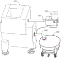
图1为本申请实施例中一种砂浆油雾回收系统的轴测向结构示意图;Fig. 1 is a schematic diagram of the axial direction measurement structure of a mortar oil mist recovery system in the embodiment of the present application;
图2为图1的主视图;Fig. 2 is the front view of Fig. 1;
图3为净化装置的结构示意图;Fig. 3 is the structural representation of purifying device;
图4为净化装置的内部结构示意图。Fig. 4 is a schematic diagram of the internal structure of the purification device.
附图标记:Reference signs:
100、切割室;110、支撑座;111、减震垫;200、净化装置;210、净化装置本体;211、进风口;212、前过滤网片;213、出油口;214、电离器; 215、集尘板;220、风机;221、出风口;300、回收装置;310、回收罐; 320、移动小车;400、第一连接管;500、第二连接管;600、第三连接管;710、第一外壳;720、第二外壳。100. Cutting chamber; 110. Support seat; 111. Shock absorbing pad; 200. Purification device; 210. Purification device body; 211. Air inlet; 212. Front filter mesh; 213. Oil outlet; 214. Ionizer; 215. Dust collection plate; 220. Fan; 221. Air outlet; 300. Recovery device; 310. Recovery tank; 320. Mobile trolley; 400. First connecting pipe; 500. Second connecting pipe; 600. Third connecting pipe ; 710, the first shell; 720, the second shell.
具体实施方式Detailed ways
本文中为部件所编序号本身,例如“第一”、“第二”等,仅用于区分所描述的对象,不具有任何顺序或技术含义。而本申请所说“连接”、“联接”,如无特别说明,均包括直接和间接连接(联接)。在本申请的描述中,需要理解的是,术语“上”、“下”、“前”、“后”、“左”、“右”、“竖直”、“水平”、“顶”、“底”、“内”、“外”、“顺时针”、“逆时针”等指示的方位或位置关系为基于附图所示的方位或位置关系,仅是为了便于描述本申请和简化描述,而不是指示或暗示所指的装置或元件必须具有特定的方位、以特定的方位构造和操作,因此不能理解为对本申请的限制。The serial numbers assigned to components in this document, such as "first", "second", etc., are only used to distinguish the described objects, and do not have any sequence or technical meaning. The "connection" and "connection" mentioned in this application all include direct and indirect connection (connection) unless otherwise specified. In the description of this application, it should be understood that the terms "upper", "lower", "front", "rear", "left", "right", "vertical", "horizontal", "top", The orientation or positional relationship indicated by "bottom", "inner", "outer", "clockwise", "counterclockwise", etc. is based on the orientation or positional relationship shown in the drawings, and is only for the convenience of describing the present application and simplifying the description , rather than indicating or implying that the device or element referred to must have a particular orientation, be constructed and operate in a particular orientation, and thus should not be construed as limiting the application.
在本申请中,除非另有明确的规定和限定,第一特征在第二特征“上”或“下”可以是第一和第二特征直接接触,或第一和第二特征通过中间媒介间接接触。而且,第一特征在第二特征“之上”、“上方”和“上面”可是第一特征在第二特征正上方或斜上方,或仅仅表示第一特征水平高度高于第二特征。第一特征在第二特征“之下”、“下方”和“下面”可以是第一特征在第二特征正下方或斜下方,或仅仅表示第一特征水平高度小于第二特征。In the present application, unless otherwise clearly specified and limited, a first feature being "on" or "under" a second feature may mean that the first and second features are in direct contact, or that the first and second features are indirect through an intermediary. touch. Moreover, "above", "above" and "above" the first feature on the second feature may mean that the first feature is directly above or obliquely above the second feature, or simply means that the first feature is higher in level than the second feature. "Below", "beneath" and "beneath" the first feature may mean that the first feature is directly below or obliquely below the second feature, or simply means that the first feature is less horizontally than the second feature.
为了更好的理解上述技术方案,下面将结合说明书附图以及具体的实施方式对上述技术方案进行详细的说明。In order to better understand the above-mentioned technical solution, the above-mentioned technical solution will be described in detail below in conjunction with the accompanying drawings and specific implementation methods.
在使用砂浆线切割晶棒时,采用的切割液为切削油和金刚石颗粒的混合物。在切片机工作过程中,切削油会雾化形成油雾,金刚石颗粒会夹带在油雾中。从而影响晶棒的切割质量。影响切割质量的因素是切割系统中的小部分金刚石颗粒随油雾一同被排出,导致整个切割系统中的金刚石颗粒数量减少,从而切割液也会随切片机的工作过程发生损失。不同类型的切片机的切割液损耗在1-4L之间。以蓝宝石切片机为例,切割液损失为2L/h。因此,为了避免影响到晶棒的切割质量,本申请实施例提供一种砂浆油雾回收系统及切片机。When using mortar to wire-cut crystal ingots, the cutting fluid used is a mixture of cutting oil and diamond particles. During the working process of the slicer, the cutting oil will be atomized to form oil mist, and diamond particles will be entrained in the oil mist. Thus affecting the cutting quality of the ingot. The factor affecting the cutting quality is that a small part of the diamond particles in the cutting system are discharged together with the oil mist, resulting in a reduction in the number of diamond particles in the entire cutting system, so that the cutting fluid will also be lost during the working process of the slicer. The cutting fluid consumption of different types of slicers is between 1-4L. Taking the sapphire slicer as an example, the loss of cutting fluid is 2L/h. Therefore, in order to avoid affecting the cutting quality of the ingot, the embodiment of the present application provides a mortar oil mist recovery system and a slicer.
如附图1、2所示,一种砂浆油雾回收系统,作用于切割室100,回收系统包括净化装置200和回收装置300。在一个实施例中,净化装置200位于切割室100的外侧,净化装置200的第一端和切割室100连通,净化装置 200包括净化装置本体210和风机220。风机220位于净化装置本体210的侧面,且风机220和净化装置本体210的侧面连接。净化装置本体210的端面设有进风口211、出油口213。净化装置本体210的内部设有电离器214,且电离器214位于出油口213的上方。回收装置300和净化装置200的第二端连通,回收装置300和切割室100连通,且回收装置300、净化装置200 以及切割室100构成一回路。从而当切割室100工作过程中,切割室100中的切削油、金刚石颗粒、以及粉末被净化装置200抽取进入到净化装置200 中,从而净化装置200可以对切削油、金刚石颗粒以及粉末进行净化分离。分离后的切削油、金刚石颗粒以及粉末进入到回收装置300中,通过净化装置200、回收装置300以及切割室100构成的回路,从而使得切削油再次进入到切割室100中循环利用。金刚石颗粒和粉末可以在回收装置300中进行收集,然后再循环用到切割室100中,从而节省辅料,避免污染车间环境或者室外环境,以及避免影响晶棒的切割质量。As shown in Figures 1 and 2, a mortar oil mist recovery system acts on the cutting
需要说明的是,为了确保切割室100工作过程中,避免切割室100中的零部件损坏,同时避免切割室100工作过程中的噪声过大,在切割室100的底端连接有支撑座110,支撑座110的底端连接有减震垫111。It should be noted that, in order to ensure that the parts in the cutting
净化装置200,如附图3、4所示,净化装置200用于对切削油、金刚石颗粒以及粉末进行分离净化。需要说明的是,净化装置200包括净化装置本体210和风机220。风机220位于净化装置本体210的侧面,且风机220和净化装置本体210的侧面连接。净化装置本体210的端面设有进风口211、出油口213。净化装置本体210的内部设有前过滤网片212,前过滤网片212 位于进风口211和出油口213之间。净化装置本体210的内部设有电离器 214,电离器214位于前过滤网片212的后侧,且电离器214位于出油口213 的上方。净化装置本体210的内部设有集尘板215,集尘板215位于电离器 214的后方且和电离器214连接,且集尘板215靠近风机220。风机220的上端面设有出风口221。从而当油雾和粉末在风机220的抽取作用下,把油雾和粉末吸入到净化装置本体210中。经过进风口211进入到净化装置本体 210中,从而经过净化装置本体210内部的前过滤网片212、电离器214以及集尘板215共同作用后,从风机220的出风口221出来的即为干净的空气,从出油口213出来的为分离后的切削油、金刚石颗粒以及粉末。从而避免直接排气的方式,油雾和粉末污染切割室或者污染外界环境。如附图3、4 所示,净化装置的工作原理为:油雾和粉末在风机220的作用下通过外置的集气罩、风管被吸入到净化装置200中。经过净化装置本体210中的前过滤网片212的过滤作用,使得较大的微粒被分离出来,通过净化装置本体210 的内部电离器214时,电离器214电晕放电使油雾中的微粒带有电荷,在电场中受到库仑力的作用转向而被吸附到金属板上,在自身重力作用下流到集油盘,经排油管道排出,实现对油雾和粉末的收集。气流通过集尘板215分离出剩余的油雾和粉末,清洁空气直接排入大气中。
需要说明的是,对于净化装置200的型号可以采购市场上成熟的型号,具体的,可以是过滤离心式油雾净化器或者静电式油雾净化器。It should be noted that for the model of the
进一步地,净化装置200位于回收装置300的上方。从而油雾和粉末经过净化装置200的净化处理后,可以使得切削油、金刚石颗粒以及粉末更好的进入到回收装置300中。净化装置200和外置的机架连接。净化装置200 在和外置的机架连接时,可以是通过螺栓的方式把净化装置200安装到外置的机架上,也可以是其他方式,在此不作具体限制。在一个实施例中,净化装置200连接有第一连接管400,第一连接管400和切割室100连通。需要说明的是,第一连接管400和净化装置200的连接方式,以及第一连接管 400和切割室100的连接方式可以有多种,包括但不限于通过喉箍的方式进行紧固。对于第一连接管400具体是钢管还是软管均可。第一连接管400为排气管道,用于把切割室100中的油雾和粉末输入到净化装置200中。Further, the
回收装置300,如附图1、2所示,回收装置300用于对从净化装置200 中分离净化后的切削油、金刚石颗粒以及粉末进行储存,配合净化装置 200、回收装置300以及切割室100构成的回路,从而有利于避免切割室100 工作过程中,切削油以及金刚石颗粒的损失,同时有利于避免工作环境或者外界环境的污染,净化后的空气排出到车间或者室外。在一个实施例中,回收装置300包括回收罐310和移动小车320。回收罐310和第二连接管500 连通。移动小车320和回收罐310连接,且移动小车320可带动回收罐310 移动。从而通过移动小车320和回收罐310的连接,有利于移动回收罐 310,便于更换新的回收罐310或者把收集到的切削油、金刚石颗粒、粉末移走。回收装置300连接有第二连接管500,第二连接管500和切割室100 连通。通过第二连接管500可以把回收罐310中收集到的切削油再次循环到切割室100中,从而可以避免切割室100工作过程中,切削油的损失。位于回收罐310中的金刚石颗粒以及粉末直接从回收罐310中进行回收,然后可以重新应用到切割室100中,从而避免金刚石颗粒的损失,确保不影响晶棒的切片质量。The
需要说明的是,为了便于使得从净化装置200中出来的切削油以及金刚石颗粒更好的进入到回收罐310中,在切削油的流动冲击下,金刚石颗粒随切削油向下进入回收装置300中。优选,第二连接管500位于第一连接管 400的下方。其中,第二连接管500和第一连接管400等高度也是可行的。第二连接管500连接有第三连接管600,第三连接管600和净化装置200连通。通过第三连接管600从而使得净化装置200和回收装置300中的回收罐 310连通,从而净化装置200中的切削油以及金刚石颗粒可以顺利的进入到回收罐310中。在一个实施例中,第三连接管600为软管。第三连接管 600、第二连接管500以及第一连接管400形状均为圆形。第三连接管600 的直径小于第一连接管400的直径,且第三连接管600的直径小于第二连接管500的直径。第三连接管600可以引导从净化装置200中分离出的切削油以及金刚石颗粒回流到回收罐310中。It should be noted that, in order to facilitate the cutting oil and diamond particles coming out of the
一种切片机,如附图2所示,切片机包括第一外壳710、第二外壳720 以及回收系统。第二外壳720位于第一外壳710的外侧。回收系统如以上提及的任一项的回收系统。其中,切割室100位于第一外壳710中,回收系统中的净化装置200位于第二外壳720中,回收系统中的回收装置300位于第二外壳720中。A slicer, as shown in FIG. 2 , the slicer includes a
工作原理/步骤:Working principle/steps:
如附图1-4所示,切割室100工作过程中,油雾和粉末通过净化装置200的抽取被净化分离,净化分离后形成的切削油、金刚石颗粒以及粉末进入到回收装置300中。通过第二连接管500的作用,最后切削油可以循环进入到切割室100中再次使用,金刚石颗粒和粉末从回收罐310中移出,金刚石可以重新应用到切割室100中;As shown in Figures 1-4, during the working process of the cutting
需要说明的是,回收罐310连接移动小车320,从而移动小车320可以带动回收罐310移动,便于更换回收罐310。It should be noted that the
技术效果:Technical effect:
1、本申请实施例中,净化装置200和切割室100连通,且净化装置200 和回收装置300连通,且净化装置200、回收装置300以及切割室100构成一回路,从而通过净化装置200对切割室100中的油雾以及粉末进行抽取,被净化装置200分离净化后进入到回收装置300中,通过回收装置300后油雾中的切削油可以继续进入到切割室100中再次使用,粉末中的金刚石颗粒在回收装置中进行收集,可以再次用于切割室中使用,解决了现有技术中常规的负压收集并外排的方案影响晶棒的切割质量的技术问题;达到了不影响晶棒的切割质量的技术效果。1. In the embodiment of the present application, the
2、本申请实施例中,净化装置200和切割室100连通,且净化装置200 和回收装置300连通,且净化装置200、回收装置300以及切割室100构成一回路,从而可以避免切割室100工作过程中,工作环境或者外界环境的污染。2. In the embodiment of the present application, the
尽管已描述了本实用新型的优选实施例,但本领域内的技术人员一旦得知了基本创造性概念,则可对这些实施例作出另外的变更和修改。所以,所附权利要求意欲解释为包括优选实施例以及落入本实用新型范围的所有变更和修改。While preferred embodiments of the present invention have been described, additional changes and modifications to these embodiments can be made by those skilled in the art once the basic inventive concept is appreciated. Therefore, the appended claims are intended to be interpreted to cover the preferred embodiment and all changes and modifications which fall within the scope of the present invention.
显然,本领域的技术人员可以对本实用新型进行各种改动和变型而不脱离本实用新型的精神和范围。这样,倘若本实用新型的这些修改和变型属于本实用新型权利要求及其等同技术的范围之内,则本实用新型也意图包含这些改动和变型在内。Obviously, those skilled in the art can make various changes and modifications to the utility model without departing from the spirit and scope of the utility model. In this way, if these modifications and variations of the utility model fall within the scope of the claims of the utility model and equivalent technologies thereof, the utility model is also intended to include these modifications and variations.
Claims (10)
Priority Applications (1)
| Application Number | Priority Date | Filing Date | Title |
|---|---|---|---|
| CN202221867785.9U CN218555019U (en) | 2022-07-19 | 2022-07-19 | Mortar oil mist recovery system and slicer |
Applications Claiming Priority (1)
| Application Number | Priority Date | Filing Date | Title |
|---|---|---|---|
| CN202221867785.9U CN218555019U (en) | 2022-07-19 | 2022-07-19 | Mortar oil mist recovery system and slicer |
Publications (1)
| Publication Number | Publication Date |
|---|---|
| CN218555019U true CN218555019U (en) | 2023-03-03 |
Family
ID=85308002
Family Applications (1)
| Application Number | Title | Priority Date | Filing Date |
|---|---|---|---|
| CN202221867785.9U Active CN218555019U (en) | 2022-07-19 | 2022-07-19 | Mortar oil mist recovery system and slicer |
Country Status (1)
| Country | Link |
|---|---|
| CN (1) | CN218555019U (en) |
Cited By (1)
| Publication number | Priority date | Publication date | Assignee | Title |
|---|---|---|---|---|
| CN117583348A (en) * | 2024-01-19 | 2024-02-23 | 山东滨州丰腾化纤绳网有限公司 | A spinning waste recovery unit for processing of chemical fibre net |
-
2022
- 2022-07-19 CN CN202221867785.9U patent/CN218555019U/en active Active
Cited By (2)
| Publication number | Priority date | Publication date | Assignee | Title |
|---|---|---|---|---|
| CN117583348A (en) * | 2024-01-19 | 2024-02-23 | 山东滨州丰腾化纤绳网有限公司 | A spinning waste recovery unit for processing of chemical fibre net |
| CN117583348B (en) * | 2024-01-19 | 2024-04-30 | 山东滨州丰腾化纤绳网有限公司 | A spinning waste recovery unit for processing of chemical fibre net |
Similar Documents
| Publication | Publication Date | Title |
|---|---|---|
| CN218193290U (en) | Automatic welding device for electrical cabinet | |
| CN219899574U (en) | Reflux dust collector for batch feeding | |
| CN213492652U (en) | An industrial air purifier with self-cleaning function | |
| CN220028761U (en) | Aluminum product perforating device | |
| CN210473446U (en) | Novel industrial dust removal device | |
| CN101976030B (en) | Dust removal machine for laser drum powder box | |
| CN218188618U (en) | Industrial dust removal system | |
| CN215276323U (en) | Movable welding fume purifier | |
| CN205269261U (en) | Pulse dust removal device for burnishing and polishing | |
| CN212283263U (en) | A kind of bag dust removal equipment | |
| CN209334966U (en) | A kind of cutting machine weldering dust collection system | |
| JP2017000929A (en) | Bag filter type dust collecting equipment and operation method of the same | |
| CN213534161U (en) | Powder spraying absorption device of offset press | |
| CN214209814U (en) | Scrubbing device for environmental design | |
| CN223289423U (en) | A lifting milling machine with dust removal effect | |
| CN210475847U (en) | A high-precision laser cutting and forming process system for a spiral track hard door frame | |
| CN220110626U (en) | Cloth bag dust remover with protection structure | |
| CN213850481U (en) | Industrial dust collector filtering device | |
| CN219389958U (en) | Airflow dust removing device in workshop ventilation system | |
| CN215847667U (en) | Online complete equipment of derusting shot blasting machine | |
| CN219003364U (en) | Vertical ring iron remover for quartz stone processing | |
| CN220344287U (en) | Broken slag cleaning device after solid waste is broken | |
| CN218697672U (en) | Workbench with central dust collector | |
| CN217139795U (en) | Blanking recovery dust remover and blanking recovery system | |
| CN218834067U (en) | Dust shaker that casting shop used |
Legal Events
| Date | Code | Title | Description |
|---|---|---|---|
| GR01 | Patent grant | ||
| GR01 | Patent grant |