CN218544620U - Novel self-cleaning air conditioning equipment - Google Patents
Novel self-cleaning air conditioning equipment Download PDFInfo
- Publication number
- CN218544620U CN218544620U CN202222631485.7U CN202222631485U CN218544620U CN 218544620 U CN218544620 U CN 218544620U CN 202222631485 U CN202222631485 U CN 202222631485U CN 218544620 U CN218544620 U CN 218544620U
- Authority
- CN
- China
- Prior art keywords
- air
- cleaning
- hole
- conditioning
- cover
- Prior art date
- Legal status (The legal status is an assumption and is not a legal conclusion. Google has not performed a legal analysis and makes no representation as to the accuracy of the status listed.)
- Expired - Fee Related
Links
Images


Landscapes
- Cleaning In General (AREA)
Abstract
本实用新型提供一种新型自清洁的空调设备,包括空调壳,卡接槽,通孔,可卡接拆卸清理盖结构,空调内部设备,支撑座和可插接清理座结构,所述的空调壳的正表面中间位置开设有通孔,且通孔的上端左右两侧分别开设有卡接槽。本实用新型遮挡盖,卡接板,通风孔,弧形遮挡板,空调壳,卡接槽和通孔的设置,有利于在使用的过程中通过拆卸遮挡盖,方便在使用的过程中对排风孔的内壁进行清理工作;插接盖,微型电机,螺纹管,移动板,缓冲弹簧和振动器的设置,有利于在自清洁的过程中通过振动器对网片进行震动工作,方便在工作中提高自清洁效果,防止灰尘堆积时间过长后影响自清洁工作。

The utility model provides a novel self-cleaning air-conditioning device, which comprises an air-conditioning shell, a clamping slot, a through hole, a clamping and detachable cleaning cover structure, internal equipment of the air conditioner, a support seat and a pluggable cleaning seat structure. A through hole is opened in the middle of the front surface of the shell, and the left and right sides of the upper end of the through hole are respectively provided with locking grooves. The setting of the shielding cover, clamping plate, ventilation hole, arc-shaped shielding plate, air-conditioning shell, clamping groove and through hole of the utility model is beneficial to remove the shielding cover in the process of use, and it is convenient to discharge air in the process of use. The inner wall of the air hole is cleaned; the plug-in cover, micro-motor, threaded pipe, moving plate, buffer spring and vibrator are set up, which is beneficial to vibrate the mesh through the vibrator during the self-cleaning process, which is convenient for working Improve the self-cleaning effect and prevent the self-cleaning work from being affected by dust accumulation for too long.
Description
技术领域technical field
本实用新型属于空调设备技术领域,尤其涉及一种新型自清洁的空调设备。The utility model belongs to the technical field of air-conditioning equipment, in particular to a novel self-cleaning air-conditioning equipment.
背景技术Background technique
空调设备在使用一段时间之后需用户自己手动拆除空调设备内的过滤网,在对过滤网进行手动的清洗,安装过程繁琐,且在安装的时候需要站在高处,对用户的安全具有一定的影响,影响用户在使用空调设备时的体验,所以人们设计了自清洁的空调设备。After the air conditioner has been used for a period of time, the user needs to manually remove the filter in the air conditioner. The installation process is cumbersome to clean the filter manually, and it is necessary to stand on a high place during installation, which has a certain impact on the safety of the user. Influence, affect the user's experience when using air-conditioning equipment, so people design self-cleaning air-conditioning equipment.
但是现有的自清洁的空调设备还存在着在进行清理的过程中由于灰尘长期积累影响清理效果以及不方便在使用的过程中对排放风口的内壁进行清理的问题。However, the existing self-cleaning air-conditioning equipment still has the problems that the long-term accumulation of dust affects the cleaning effect during the cleaning process, and it is inconvenient to clean the inner wall of the discharge air outlet during use.
因此,发明一种新型自清洁的空调设备显得非常必要。Therefore, it is necessary to invent a kind of novel self-cleaning air conditioner.
实用新型内容Utility model content
为了解决上述技术问题,本实用新型提供一种新型自清洁的空调设备,以解决现有的自清洁的空调设备还存在着在进行清理的过程中由于灰尘长期积累影响清理效果以及不方便在使用的过程中对排放风口的内壁进行清理的问题。一种新型自清洁的空调设备,包括空调壳,卡接槽,通孔,可卡接拆卸清理盖结构,空调内部设备,支撑座和可插接清理座结构,所述的空调壳的正表面中间位置开设有通孔,且通孔的上端左右两侧分别开设有卡接槽;所述的可卡接拆卸清理盖结构固定在通孔的内部;所述的空调内部设备螺栓固定在空调壳的内部;所述的可插接清理座结构安装在空调壳的左侧内部前面。In order to solve the above-mentioned technical problems, the utility model provides a new type of self-cleaning air-conditioning equipment to solve the problem that the existing self-cleaning air-conditioning equipment still has problems in the cleaning process due to long-term accumulation of dust that affects the cleaning effect and is inconvenient to use. During the process of cleaning the inner wall of the exhaust air outlet. A new type of self-cleaning air-conditioning equipment, including an air-conditioning shell, a clamping groove, a through hole, a clamping and detachable cleaning cover structure, internal equipment of the air conditioner, a support seat and a pluggable cleaning seat structure, the front surface of the air-conditioning shell A through hole is opened in the middle position, and the left and right sides of the upper end of the through hole are respectively provided with clamping grooves; the detachable cleaning cover structure is fixed inside the through hole; the air conditioner internal equipment bolts are fixed on the air conditioner shell The inside; the pluggable cleaning seat structure is installed in front of the left side of the air-conditioning shell.
与现有技术相比,本实用新型的有益效果为:Compared with the prior art, the beneficial effects of the utility model are:
1.本实用新型中,所述的遮挡盖,卡接板,通风孔,弧形遮挡板,空调壳,卡接槽和通孔的设置,有利于在使用的过程中通过拆卸遮挡盖,方便在使用的过程中对排风孔的内壁进行清理工作。1. In the utility model, the setting of the shielding cover, snap-in plate, ventilation hole, arc-shaped shielding plate, air-conditioning shell, snap-in groove and through hole is beneficial to remove the shielding cover during use, which is convenient Clean the inner wall of the exhaust hole during use.
2.本实用新型中,所述的插接盖,微型电机,螺纹管,移动板,缓冲弹簧和振动器的设置,有利于在自清洁的过程中通过振动器对网片进行震动工作,方便在工作中提高自清洁效果,防止灰尘堆积时间过长后影响自清洁工作。2. In the utility model, the setting of the plug-in cover, the micro motor, the threaded pipe, the moving plate, the buffer spring and the vibrator is beneficial to vibrate the mesh through the vibrator during the self-cleaning process, which is convenient Improve the self-cleaning effect during work, and prevent the self-cleaning work from being affected by dust accumulation for too long.
附图说明Description of drawings
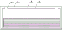
图1是本实用新型的结构示意图。Fig. 1 is the structural representation of the utility model.
图2是本实用新型的可卡接拆卸清理盖结构的结构示意图。Fig. 2 is a structural schematic diagram of the detachable cleaning cover structure of the utility model.
图3是本实用新型的可插接清理座结构的结构示意图。Fig. 3 is a structural schematic diagram of the structure of the pluggable cleaning seat of the present invention.
图4是本实用新型的内视图。Fig. 4 is an internal view of the utility model.
图中:In the picture:
1、空调壳;2、卡接槽;3、通孔;4、可卡接拆卸清理盖结构;41、遮挡盖;42、卡接板;43、通风孔;44、弧形遮挡板;5、空调内部设备;6、支撑座;7、可插接清理座结构;71、插接盖;72、微型电机;73、螺纹管;74、移动板;75、收集盒;76、缓冲弹簧;77、振动器。1. Air conditioning shell; 2. Clamping groove; 3. Through hole; 4. Clamping and detachable cleaning cover structure; 41. Shielding cover; 42. Clamping plate; 43. Ventilation hole; 44. Arc shielding plate; 5 . Internal equipment of air conditioner; 6. Support seat; 7. Plug-in cleaning seat structure; 71. Plug-in cover; 72. Micro motor; 73. Threaded pipe; 74. Moving plate; 75. Collection box; 77. Vibrator.
具体实施方式Detailed ways
下面结合附图对本实用新型进行具体描述,如附图1和附图2所示,一种新型自清洁的空调设备,包括空调壳1,卡接槽2,通孔3,可卡接拆卸清理盖结构4,空调内部设备5,支撑座6和可插接清理座结构7,所述的空调壳1的正表面中间位置开设有通孔3,且通孔3的上端左右两侧分别开设有卡接槽2;所述的可卡接拆卸清理盖结构4固定在通孔3的内部;所述的空调内部设备5螺栓固定在空调壳1的内部;所述的可插接清理座结构7安装在空调壳1的左侧内部前面;所述的可卡接拆卸清理盖结构4包括遮挡盖41,卡接板42,通风孔43和弧形遮挡板44,所述的遮挡盖41的上端左右两侧分别一体化设置有卡接板42;所述的遮挡盖41的正表面下部开设有通风孔43;所述的通风孔43的内壁从上到下依次螺钉固定有弧形遮挡板44;进行使用时,将空调壳1固定在合适的位置,然后接通外部电源以及空调壳1内部的控制芯片,在进行工作的过程中通过遮挡盖41进行内部防护工作,防止工作中空调内部设备5受到损坏,同时通过弧形遮挡板44进行灰尘遮挡工作。The utility model is described in detail below in conjunction with the accompanying drawings. As shown in accompanying
本实施方案中,结合附图3所示,所述的可插接清理座结构7包括插接盖71,微型电机72,螺纹管73,移动板74,收集盒75,缓冲弹簧76和振动器77,所述的插接盖71的右侧上部前面固定有微型电机72;所述的微型电机72的输出轴外部螺栓连接有螺纹管73;所述的螺纹管73的外壁螺纹连接有移动板74,且移动板74的下端滑动插接在收集盒75的内部;所述的收集盒75的内部底端右侧分别螺栓连接有缓冲弹簧76;所述的缓冲弹簧76的上端分别螺栓连接在振动器77的下端左右两侧;在长时间进行工作的过程中,通过外部空调遥控设施进行操作,在进行清理的过程中通过螺纹管73和移动板74螺纹连接设置,使移动板74进行左右移动工作,在移动板74移动的过程中对插接盖71右侧设置的网片进行清理工作,同时通过振动器77对网片进行震动工作,方便在使用的过程中提高空调设备的自清洁效果,进而完成工作。In this embodiment, as shown in Figure 3, the pluggable cleaning seat structure 7 includes a
本实施方案中,具体的,所述的卡接槽2和通孔3连通设置,且通孔3的下端从左到右依次开设有插接孔。In this embodiment, specifically, the
本实施方案中,具体的,所述的遮挡盖41的下端从左到右依次设置有插接柱;所述的弧形遮挡板44采用弧形的PVC板。In this embodiment, specifically, the lower end of the
本实施方案中,具体的,所述的遮挡盖41下端设置的插接柱从左到右依次插接在通孔3下端设置的插接孔内部;所述的卡接板42分别卡接在卡接槽2的内部。In this embodiment, specifically, the insertion posts provided at the lower end of the
本实施方案中,具体的,所述的移动板74的后端依次固定有尼龙刷毛;所述的插接盖71的右侧后面螺钉连接不锈钢网片且与移动板74后端设置的尼龙刷毛接触设置;所述的振动器77螺栓固定在不锈钢网片的下端右侧。In this embodiment, specifically, nylon bristles are sequentially fixed on the rear end of the moving
本实施方案中,具体的,所述的插接盖71插接在空调壳1的左侧内部前面;所述的收集盒75设置在空调壳1的内部底端前面;所述的螺纹管73的右端插接在空调壳1的右侧内壁上部,且连接处设置有轴承。In this embodiment, specifically, the plug-in
工作原理working principle
本实用新型中,进行使用时,将空调壳1固定在合适的位置,然后接通外部电源以及空调壳1内部的控制芯片,在进行工作的过程中通过遮挡盖41进行内部防护工作,防止工作中空调内部设备5受到损坏,同时通过弧形遮挡板44进行灰尘遮挡工作,在长时间进行工作的过程中,通过外部空调遥控设施进行操作,在进行清理的过程中通过螺纹管73和移动板74螺纹连接设置,使移动板74进行左右移动工作,在移动板74移动的过程中对插接盖71右侧设置的网片进行清理工作,同时通过振动器77对网片进行震动工作,方便在使用的过程中提高空调设备的自清洁效果,进而完成工作。In the utility model, when in use, the air-conditioning shell 1 is fixed in a suitable position, and then the external power supply and the control chip inside the air-conditioning shell 1 are connected, and the internal protection work is carried out through the
利用本实用新型所述的技术方案,或本领域的技术人员在本实用新型技术方案的启发下,设计出类似的技术方案,而达到上述技术效果的,均是落入本实用新型的保护范围。Utilize the technical solution described in the utility model, or those skilled in the art design similar technical solutions under the inspiration of the technical solution of the utility model, and achieve the above-mentioned technical effect, all fall into the protection scope of the utility model .
Claims (5)
Priority Applications (1)
| Application Number | Priority Date | Filing Date | Title |
|---|---|---|---|
| CN202222631485.7U CN218544620U (en) | 2022-10-08 | 2022-10-08 | Novel self-cleaning air conditioning equipment |
Applications Claiming Priority (1)
| Application Number | Priority Date | Filing Date | Title |
|---|---|---|---|
| CN202222631485.7U CN218544620U (en) | 2022-10-08 | 2022-10-08 | Novel self-cleaning air conditioning equipment |
Publications (1)
| Publication Number | Publication Date |
|---|---|
| CN218544620U true CN218544620U (en) | 2023-02-28 |
Family
ID=85276562
Family Applications (1)
| Application Number | Title | Priority Date | Filing Date |
|---|---|---|---|
| CN202222631485.7U Expired - Fee Related CN218544620U (en) | 2022-10-08 | 2022-10-08 | Novel self-cleaning air conditioning equipment |
Country Status (1)
| Country | Link |
|---|---|
| CN (1) | CN218544620U (en) |
-
2022
- 2022-10-08 CN CN202222631485.7U patent/CN218544620U/en not_active Expired - Fee Related
Similar Documents
| Publication | Publication Date | Title |
|---|---|---|
| CN101261032B (en) | Ventilating system automatic dust removing apparatus | |
| CN205842972U (en) | A kind of new quiet dust arrester of air blower | |
| CN212204946U (en) | Energy-saving environment-friendly ventilation device | |
| CN220439437U (en) | Low-voltage switch shell with self-cleaning function | |
| CN218096266U (en) | Air purification equipment for air conditioner | |
| CN208920554U (en) | A purification module fixing device of a fresh air device | |
| CN217653992U (en) | Ventilation device for refrigeration engineering | |
| CN216693912U (en) | High-temperature sterilization negative pressure type air purifier | |
| CN216342280U (en) | Subway shaft ventilation unit | |
| CN216223406U (en) | Dust collecting equipment for construction | |
| CN110102524A (en) | A kind of coaxial air curtain cleaner | |
| CN220539977U (en) | Dust collector for ventilation blower | |
| CN211098085U (en) | A fume purifier with cleaning function | |
| CN210939830U (en) | Concrete block surface machining equipment | |
| CN209676248U (en) | A kind of easy-to-mount communication apparatus sound arrester | |
| CN218627266U (en) | Air purifier's filter screen mounting structure | |
| CN209109738U (en) | A kind of Airshower chamber equipped with ultrasonic cleaning equipment | |
| CN223580114U (en) | A top-mounted air supply device | |
| CN216631739U (en) | Automatic cleaning mechanism for discharge needle of ion fan | |
| CN220436691U (en) | Novel energy-conserving new trend of building environment purifies device | |
| CN208178015U (en) | A kind of cleaning plant of microorganism superclean bench | |
| CN221301520U (en) | Indoor clarification plant convenient to maintain | |
| CN210135652U (en) | New material air purifier | |
| CN218591231U (en) | Dust removal removes electrostatic devices | |
| CN209348296U (en) | HEPA filter without partition |
Legal Events
| Date | Code | Title | Description |
|---|---|---|---|
| GR01 | Patent grant | ||
| GR01 | Patent grant | ||
| TR01 | Transfer of patent right |
Effective date of registration: 20231024 Address after: Room 1809, No. 101 Science Avenue, Huangpu District, Guangzhou City, Guangdong Province, 510000 Patentee after: Lianqu Technology Development Co.,Ltd. Address before: Room 1304, Building 3, Entrepreneurship Center, No. 82, Huayuan West Road, Chuzhou, Anhui Province, 239000 Patentee before: ANHUI XINGHE ENERGY SAVING TECHNOLOGY Co.,Ltd. |
|
| TR01 | Transfer of patent right | ||
| CF01 | Termination of patent right due to non-payment of annual fee |
Granted publication date: 20230228 |
|
| CF01 | Termination of patent right due to non-payment of annual fee |