CN218523582U - Air filtering device for gas-electric double-drive draught fan - Google Patents
Air filtering device for gas-electric double-drive draught fan Download PDFInfo
- Publication number
- CN218523582U CN218523582U CN202222379998.3U CN202222379998U CN218523582U CN 218523582 U CN218523582 U CN 218523582U CN 202222379998 U CN202222379998 U CN 202222379998U CN 218523582 U CN218523582 U CN 218523582U
- Authority
- CN
- China
- Prior art keywords
- buckle
- air filtering
- filtering device
- gas
- main body
- Prior art date
- Legal status (The legal status is an assumption and is not a legal conclusion. Google has not performed a legal analysis and makes no representation as to the accuracy of the status listed.)
- Active
Links
- 238000001914 filtration Methods 0.000 title claims description 13
- 238000009434 installation Methods 0.000 claims description 21
- 239000002184 metal Substances 0.000 claims description 14
- 238000000034 method Methods 0.000 claims description 3
- 238000005728 strengthening Methods 0.000 claims description 2
- 230000003014 reinforcing effect Effects 0.000 claims 1
- 238000003466 welding Methods 0.000 claims 1
- 238000004140 cleaning Methods 0.000 description 15
- 230000001681 protective effect Effects 0.000 description 11
- 239000000428 dust Substances 0.000 description 8
- 238000001816 cooling Methods 0.000 description 4
- 239000007789 gas Substances 0.000 description 4
- 238000009423 ventilation Methods 0.000 description 4
- 230000006837 decompression Effects 0.000 description 3
- 238000010586 diagram Methods 0.000 description 2
- 239000012535 impurity Substances 0.000 description 2
- JTJMJGYZQZDUJJ-UHFFFAOYSA-N phencyclidine Chemical class C1CCCCN1C1(C=2C=CC=CC=2)CCCCC1 JTJMJGYZQZDUJJ-UHFFFAOYSA-N 0.000 description 2
- UGFAIRIUMAVXCW-UHFFFAOYSA-N Carbon monoxide Chemical compound [O+]#[C-] UGFAIRIUMAVXCW-UHFFFAOYSA-N 0.000 description 1
- 238000004378 air conditioning Methods 0.000 description 1
- 230000009286 beneficial effect Effects 0.000 description 1
- 238000001035 drying Methods 0.000 description 1
- 238000005516 engineering process Methods 0.000 description 1
- 239000000284 extract Substances 0.000 description 1
- 238000001125 extrusion Methods 0.000 description 1
- 239000003546 flue gas Substances 0.000 description 1
- 239000012530 fluid Substances 0.000 description 1
- 230000006698 induction Effects 0.000 description 1
- 238000002156 mixing Methods 0.000 description 1
Images


Landscapes
- Structures Of Non-Positive Displacement Pumps (AREA)
Abstract
本实用新型公开了一种气电双驱引风机用滤风装置,涉及引风机技术领域,为解决现有气电双驱引风机输入端的滤风在使用的过程中,会随着时间累积,导致卡扣的过滤网不便清洁的问题。所述内腔体安装在所述可滤风装置主体内部的后侧,所述内腔体内壁两侧的内部均设置有内移动卡扣连接杆,且内移动卡扣连接杆设置有四个,四个所述内移动卡扣连接杆两端均与可滤风装置主体固定连接,四个所述内移动卡扣连接杆之间设置有滑轮电轴,且滑轮电轴设置有两个,两个所述滑轮电轴均通过卡扣凸起块与内移动卡扣连接杆上下转动移动,且卡扣凸起块设置有若干个,若干个所述卡扣凸起块均与滑轮电轴外壁一圈固定连接,两个所述滑轮电轴之间设置有转动辊轴。
The utility model discloses an air filter device for a gas-electric dual-drive induced draft fan, which relates to the technical field of induced draft fans. In order to solve the problem that the filter air at the input end of the existing gas-electric dual-drive induced draft fan will accumulate over time during use, The problem that caused the filter screen of the buckle to be inconvenient to clean. The inner cavity body is installed on the rear side of the main body of the filterable air device, and both sides of the inner wall of the inner cavity are provided with inner movable buckle connecting rods, and the inner movable buckle connecting rods are provided with four , both ends of the four internally movable buckle connecting rods are fixedly connected to the main body of the filterable air device, a pulley electric shaft is arranged between the four internally movable buckle connecting rods, and there are two pulley electric shafts, The two pulley electric shafts are rotated up and down through the buckle protrusions and the inner moving buckle connecting rod, and there are several buckle protrusions, and several of the buckle protrusions are connected to the pulley electric shaft. One circle of the outer wall is fixedly connected, and a rotating roller shaft is arranged between the two pulley electric shafts.
Description
技术领域technical field
本实用新型涉及引风机技术领域,具体为一种气电双驱引风机用滤风装置。The utility model relates to the technical field of induced draft fans, in particular to an air filter device for a gas-electric dual-drive induced draft fan.
背景技术Background technique
引风机是通过叶轮转动产生负压,进而从系统(设备)抽取空气的一种设备,一般安装在锅炉尾端,用于抽取炉膛内的热烟气。日常生活中,通常将通风机按正、负压使用方式不同分为引风机(负压使用)和鼓风机(正压使用)。引风机广泛用于工厂、矿井、隧道、冷却塔、车辆、船舶和建筑物的通风、排尘和冷却;锅炉和工业炉窑的通风和引风;空气调节设备和家用电器设备中的冷却和通风;谷物的烘干和选送;风洞风源和气垫船的充气和推进等。 引风机的工作原理与透平压缩机基本相同,只是由于气体流速较低,压力变化不大,一般不需要考虑气体比容的变化,即把气体作为不可压缩流体处理。The induced draft fan is a device that generates negative pressure through the rotation of the impeller and then extracts air from the system (equipment). It is generally installed at the end of the boiler to extract the hot flue gas in the furnace. In daily life, ventilators are usually divided into induced draft fans (for negative pressure use) and blowers (for positive pressure use) according to the positive and negative pressure use methods. Induced fans are widely used in ventilation, dust removal and cooling of factories, mines, tunnels, cooling towers, vehicles, ships and buildings; ventilation and induction of boilers and industrial furnaces; cooling and cooling of air conditioning equipment and household appliances Ventilation; drying and selection of grain; wind tunnel wind source and inflation and propulsion of hovercraft, etc. The working principle of the induced draft fan is basically the same as that of the turbo compressor, but because the gas flow rate is low and the pressure changes little, generally there is no need to consider the change of the gas specific volume, that is, the gas is treated as an incompressible fluid.
例如公告号为202111051230.7(一种汽电双驱汽轮机排气管道通气结构),包括:烟道管,所述烟道管的入口端设置有除尘器出口,所述烟道管的出口端设置有引风机入口,减压集风装置,用于对所述除尘器出口端较大风压进行压力降低和风涡转正的减压集风装置设置于所述除尘器出口的内部。本发明减压集风装置内部组件的配合作用以及风盘转片的结构设置,利用离心力和风力带动功能,实现了对刚从除尘器出来气体中局部气旋的混合,避免了除尘器出口接口端受到局部气旋的冲击损坏现象,此外通过风压清洁装置内部组件的配合作用与清洁片的结构设置,利用风能转化的转动力和挤压力,达到了对烟道口的清洁功能,延长了内管接口清理周期,保障了排气的稳定进行For example, the announcement number is 202111051230.7 (a steam-electric double-drive steam turbine exhaust pipe ventilation structure), including: a flue pipe, the inlet end of the flue pipe is provided with a dust collector outlet, and the outlet end of the flue pipe is provided with The inlet of the induced draft fan, the decompression and air collection device, and the decompression and air collection device for reducing the pressure of the large wind pressure at the outlet of the dust collector and turning the wind vortex to normal are arranged inside the outlet of the dust collector. The coordination function of the internal components of the decompression and wind collection device of the present invention and the structural arrangement of the wind disk rotating piece utilize centrifugal force and wind force to drive the function, realize the mixing of local cyclones in the gas just coming out of the dust collector, and avoid the outlet port of the dust collector It is damaged by the impact of local cyclones. In addition, through the cooperation of the internal components of the wind pressure cleaning device and the structural setting of the cleaning sheet, the rotation force and extrusion force converted by wind energy are used to achieve the cleaning function of the flue opening and extend the inner pipe. The interface cleaning cycle ensures the stable exhaust
但是,现有的气电双驱引风机输入端的滤风在使用的过程中,会随着时间累积,导致卡扣的过滤网不便清洁的问题;因此,不满足现有的需求,对此我们提出了一种气电双驱引风机用滤风装置。However, the filter air at the input end of the existing gas-electric dual-drive induced draft fan will accumulate over time during use, resulting in the problem that the snap-on filter screen is inconvenient to clean; therefore, it does not meet the existing needs. An air filter device for a gas-electric dual-drive induced draft fan is proposed.
实用新型内容Utility model content
本实用新型的目的在于提供一种气电双驱引风机用滤风装置,以解决上述背景技术中提出的现有气电双驱引风机输入端的滤风在使用的过程中,会随着时间累积,导致卡扣的过滤网不便清洁的问题。The purpose of this utility model is to provide an air filter device for a gas-electric dual-drive induced draft fan, so as to solve the problem that the filter air at the input end of the existing gas-electric dual-drive induced draft fan proposed in the above-mentioned background technology will deteriorate with time during use. Accumulated, resulting in the inconvenient cleaning of the snap-on filter.
为实现上述目的,本实用新型提供如下技术方案:一种气电双驱引风机用滤风装置,包括:可滤风装置主体,所述可滤风装置主体上端面和下端面的后侧均设置有连接安装片,且连接安装片设置有四个,四个所述连接安装片均与可滤风装置主体上端面和下端面的后侧固定连接,四个所述连接安装片的内部均设置有预留安装孔槽,且预留安装孔槽与连接安装片一体式形成;In order to achieve the above purpose, the utility model provides the following technical solutions: a gas-electric dual-drive induced draft fan air filter device, including: a main body of the filterable air device, the rear sides of the upper end surface and the lower end surface of the main body of the filterable air device are both There are four connecting and installing pieces, and the four connecting and installing pieces are all fixedly connected with the rear side of the upper end surface and the lower end surface of the main body of the filterable air device, and the insides of the four connecting and installing pieces are all There is a reserved installation hole slot, and the reserved installation hole slot is integrally formed with the connecting installation piece;
还包括:Also includes:
内腔体,其安装在所述可滤风装置主体内部的后侧,所述内腔体内壁两侧的内部均设置有内移动卡扣连接杆,且内移动卡扣连接杆设置有四个,四个所述内移动卡扣连接杆两端均与可滤风装置主体固定连接,四个所述内移动卡扣连接杆之间设置有滑轮电轴,且滑轮电轴设置有两个,两个所述滑轮电轴均通过卡扣凸起块与内移动卡扣连接杆上下转动移动,且卡扣凸起块设置有若干个,若干个所述卡扣凸起块均与滑轮电轴外壁一圈固定连接,两个所述滑轮电轴之间设置有转动辊轴,所述转动辊轴外壁的一圈设置有清理毛刷端头,且清理毛刷端头设置有若干个,若干个所述清理毛刷端头均与转动辊轴固定连接。The inner cavity is installed on the rear side of the main body of the filterable air device. The interior of both sides of the inner wall of the inner cavity is provided with an inner movable buckle connecting rod, and the inner movable buckled connecting rod is provided with four , both ends of the four internally moving buckle connecting rods are fixedly connected to the main body of the filterable air device, there are pulley electric shafts arranged between the four internally moving buckle connecting rods, and there are two pulley electric shafts, The two pulley electric shafts are rotated and moved up and down through the buckle protrusions and the inner moving buckle connecting rod, and there are several buckle protrusions, and several of the buckle protrusions are connected to the pulley electric shaft. One circle of the outer wall is fixedly connected, and a rotating roller shaft is arranged between the two electric shafts of the pulleys. One circle of the outer wall of the rotating roller shaft is provided with cleaning brush ends, and several cleaning brush ends are provided. The ends of the cleaning brushes are all fixedly connected with the rotating roller shaft.
优选的,四个所述内移动卡扣连接杆的内部均设置有卡扣内凹槽,且卡扣内凹槽设置有若干个。Preferably, the insides of the four inner movable buckle connecting rods are all provided with buckle inner grooves, and there are several buckle inner grooves.
优选的,所述可滤风装置主体的前端面设置有加强防护遮挡板,且加强防护遮挡板设置有三个,三个所述加强防护遮挡板的两端均与可滤风装置主体一体式形成。Preferably, the front end of the main body of the filterable air device is provided with a reinforced protective shield, and there are three reinforced protective shields, and the two ends of the three reinforced protective shields are integrally formed with the main body of the filterable air device .
优选的,三个所述加强防护遮挡板之间设置有内凹槽腔体,且内凹槽腔体设置有四个。Preferably, inner groove cavities are arranged between the three reinforced protective shielding plates, and there are four inner groove cavities.
优选的,所述内腔体内部的一侧设置有金属过滤网罩层,且金属过滤网罩层四周均与可滤风装置主体焊接连接。Preferably, one side of the inner cavity is provided with a metal filter mesh cover layer, and the surroundings of the metal filter mesh cover layer are welded to the main body of the air-filtering device.
优选的,所述金属过滤网罩层的后侧设置有细致过滤网层,且细致过滤网层与可滤风装置主体可拆卸式连接。Preferably, a fine filter mesh layer is provided on the rear side of the metal filter mesh cover layer, and the fine filter mesh layer is detachably connected to the main body of the air filter device.
与现有技术相比,本实用新型的有益效果是:Compared with the prior art, the beneficial effects of the utility model are:
1、本实用新型通过设置的内移动卡扣连接杆、滑轮电轴、转动辊轴和清理毛刷端头,正转反转滑轮电轴,可有效带动转动辊轴通过旋转实现位置上下的调节,在转动辊轴进行转动的时候,设置的清理毛刷端头可以直接作用于细致过滤网层表面,使之表面的粉尘沉积物得以进行清理,避免现有的气电双驱引风机输入端的滤风在使用的过程中,会随着时间累积,导致卡扣的过滤网不便清洁的问题。1. The utility model can effectively drive the rotating roller shaft to adjust the position up and down through the rotation through the set internally moving buckle connecting rod, the pulley electric shaft, the rotating roller shaft and the end of the cleaning brush, and the forward and reverse rotation of the pulley electric shaft. , when the rotating roller shaft is rotating, the end of the cleaning brush set can directly act on the surface of the fine filter layer, so that the dust deposits on the surface can be cleaned, avoiding the input end of the existing gas-electric dual-drive induced draft fan. During the use of the filter, it will accumulate over time, resulting in the problem that the snap-on filter is inconvenient to clean.
2、通过在可滤风装置主体的内部设置的金属过滤网罩层,可以有效的为装置内部的元件提供保护,减少异物杂质被吸入,导致内部元件或者细致过滤网层被损坏的情况,同时设置的加强防护遮挡板也有效避免大块物件被吸入,对其他物件造成损坏的问题发生。2. Through the metal filter mesh cover layer set inside the main body of the filterable air device, it can effectively provide protection for the components inside the device, reduce the inhalation of foreign matter and impurities, and cause damage to the internal components or the fine filter layer. At the same time The set reinforced protective baffle can also effectively avoid the problem of large objects being sucked in and causing damage to other objects.
附图说明Description of drawings
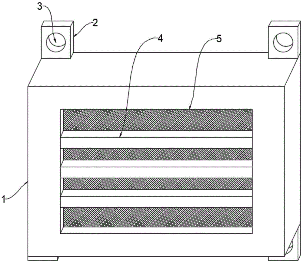
图1为本实用新型的整体结构示意图;Fig. 1 is the overall structural representation of the utility model;
图2为本实用新型的内部结构示意图;Fig. 2 is a schematic diagram of the internal structure of the utility model;
图3为本实用新型的内移动卡扣连接杆局部结构示意图;Fig. 3 is a schematic diagram of the partial structure of the internally movable buckle connecting rod of the present invention;
图中:1、可滤风装置主体;2、连接安装片;3、预留安装孔槽;4、加强防护遮挡板;5、内凹槽腔体;6、金属过滤网罩层;7、细致过滤网层;8、内移动卡扣连接杆;9、滑轮电轴;10、卡扣凸起块;11、转动辊轴;12、清理毛刷端头;13、内腔体;14、卡扣内凹槽。In the figure: 1. The main body of the filterable air device; 2. Connecting the installation piece; 3. Reserving the installation hole slot; 4. Strengthening the protective shield; 5. The inner groove cavity; 6. The metal filter mesh cover layer; 7. Meticulous filter layer; 8. Inwardly moving buckle connecting rod; 9. Pulley electric shaft; 10. Buckle raised block; 11. Rotating roller shaft; 12. Cleaning the brush end; 13. Inner cavity; 14. Buckle inner groove.
具体实施方式Detailed ways
下面将结合本实用新型实施例中的附图,对本实用新型实施例中的技术方案进行清楚、完整地描述,显然,所描述的实施例仅仅是本实用新型一部分实施例,而不是全部的实施例。The technical solutions in the embodiments of the present invention will be clearly and completely described below in conjunction with the accompanying drawings in the embodiments of the present invention. Obviously, the described embodiments are only part of the embodiments of the present invention, not all of them. example.
请参阅图1-3,本实用新型提供的一种实施例:一种气电双驱引风机用滤风装置,包括:可滤风装置主体1,可滤风装置主体1上端面和下端面的后侧均设置有连接安装片2,且连接安装片2设置有四个,四个连接安装片2均与可滤风装置主体1上端面和下端面的后侧固定连接,四个连接安装片2的内部均设置有预留安装孔槽3,且预留安装孔槽3与连接安装片2一体式形成;Please refer to Fig. 1-3, an embodiment provided by the utility model: an air filter device for a gas-electric dual-drive induced draft fan, including: a main body 1 of the air filter device, an upper end surface and a lower end surface of the main body 1 of the air filter device The rear side of each is provided with connection installation pieces 2, and there are four connection installation pieces 2, and the four connection installation pieces 2 are all fixedly connected with the rear side of the upper end surface and the lower end surface of the air filter device main body 1, and the four connection installation pieces The interior of the piece 2 is provided with a
还包括:Also includes:
内腔体13,其安装在可滤风装置主体1内部的后侧,内腔体13内壁两侧的内部均设置有内移动卡扣连接杆8,且内移动卡扣连接杆8设置有四个,四个内移动卡扣连接杆8两端均与可滤风装置主体1固定连接,四个内移动卡扣连接杆8之间设置有滑轮电轴9,且滑轮电轴9设置有两个,两个滑轮电轴9均通过卡扣凸起块10与内移动卡扣连接杆8上下转动移动,且卡扣凸起块10设置有若干个,若干个卡扣凸起块10均与滑轮电轴9外壁一圈固定连接,两个滑轮电轴9之间设置有转动辊轴11,转动辊轴11外壁的一圈设置有清理毛刷端头12,且清理毛刷端头12设置有若干个,若干个清理毛刷端头12均与转动辊轴11固定连接。The
请参阅图3,四个内移动卡扣连接杆8的内部均设置有卡扣内凹槽14,且卡扣内凹槽14设置有若干个。Please refer to FIG. 3 , the insides of the four internally movable
请参阅图1和图2,可滤风装置主体1的前端面设置有加强防护遮挡板4,且加强防护遮挡板4设置有三个,三个加强防护遮挡板4的两端均与可滤风装置主体1一体式形成,加强防护遮挡板4的设置,避免大型异物被吸入。Please refer to Fig. 1 and Fig. 2, the front face of the air filter device main body 1 is provided with a reinforced
请参阅图1和图2,三个加强防护遮挡板4之间设置有内凹槽腔体5,且内凹槽腔体5设置有四个。Please refer to FIG. 1 and FIG. 2 , there are
请参阅图2,内腔体13内部的一侧设置有金属过滤网罩层6,且金属过滤网罩层6四周均与可滤风装置主体1焊接连接,金属过滤网罩层6的设置,可以有效的加强对内部元件的保护。Referring to Fig. 2, one side of the
请参阅图2,金属过滤网罩层6的后侧设置有细致过滤网层7,且细致过滤网层7与可滤风装置主体1可拆卸式连接,可拆卸式连接使得安装上操作便捷。Please refer to FIG. 2 , a
工作原理:该装置在使用前,将外部螺栓通过预留安装孔槽3将可滤风装置主体1与引风机主体进行螺纹连接,使用时,由金属过滤网罩层6为该装置内部的元件提供保护,减少异物杂质被吸入,导致内部元件或者细致过滤网层7被损坏的情况发生,在使用一端时间后,可以通过正转反转滑轮电轴9,有效带动转动辊轴11进行旋转以及位置上下操作的调节,在转动辊轴11进行转动的时候,设置的清理毛刷端头12可以直接作用于细致过滤网层7表面,使之表面的粉尘沉积物得以进行清理。Working principle: Before using the device, thread the external bolts through the reserved
对于本领域技术人员而言,显然本实用新型不限于上述示范性实施例的细节,而且在不背离本实用新型的精神或基本特征的情况下,能够以其他的具体形式实现本实用新型。因此,无论从哪一点来看,均应将实施例看作是示范性的,而且是非限制性的,本实用新型的范围由所附权利要求而不是上述说明限定,因此旨在将落在权利要求的等同要件的含义和范围内的所有变化囊括在本实用新型内。不应将权利要求中的任何附图标记视为限制所涉及的权利要求。It is obvious to those skilled in the art that the present invention is not limited to the details of the above exemplary embodiments, and that the present invention can be implemented in other specific forms without departing from the spirit or essential features of the present invention. Therefore, no matter from all points of view, the embodiments should be regarded as exemplary and non-restrictive, and the scope of the present invention is defined by the appended claims rather than the above description, so it is intended to fall within the scope of the claims All changes within the meaning and range of equivalents of the required elements are included in the present invention. Any reference sign in a claim should not be construed as limiting the claim concerned.
Claims (6)
Priority Applications (1)
| Application Number | Priority Date | Filing Date | Title |
|---|---|---|---|
| CN202222379998.3U CN218523582U (en) | 2022-09-08 | 2022-09-08 | Air filtering device for gas-electric double-drive draught fan |
Applications Claiming Priority (1)
| Application Number | Priority Date | Filing Date | Title |
|---|---|---|---|
| CN202222379998.3U CN218523582U (en) | 2022-09-08 | 2022-09-08 | Air filtering device for gas-electric double-drive draught fan |
Publications (1)
| Publication Number | Publication Date |
|---|---|
| CN218523582U true CN218523582U (en) | 2023-02-24 |
Family
ID=85245268
Family Applications (1)
| Application Number | Title | Priority Date | Filing Date |
|---|---|---|---|
| CN202222379998.3U Active CN218523582U (en) | 2022-09-08 | 2022-09-08 | Air filtering device for gas-electric double-drive draught fan |
Country Status (1)
| Country | Link |
|---|---|
| CN (1) | CN218523582U (en) |
-
2022
- 2022-09-08 CN CN202222379998.3U patent/CN218523582U/en active Active
Similar Documents
| Publication | Publication Date | Title |
|---|---|---|
| CN214468759U (en) | Draught fan for boiler smoke exhaust | |
| CN209828529U (en) | Dust removal device for draught fan | |
| CN102225280A (en) | Dedusting equipment and dust collector thereof | |
| CN216343073U (en) | Centrifugal force supply structure of centrifugal fire-fighting smoke exhaust fan | |
| CN211116678U (en) | Low-noise centrifugal fan | |
| CN214788072U (en) | Centrifugal ventilator for aluminum part smelting furnace | |
| CN209900870U (en) | An induced draft fan for exhaust gas treatment in electrolytic aluminum industry | |
| CN221647203U (en) | A high efficiency centrifugal fan | |
| CN219413017U (en) | Impeller of cooking fume exhauster | |
| CN202431366U (en) | Environment-friendly energy-saving generator set | |
| CN221628449U (en) | Ventilation fan with filtering mechanism | |
| CN206785743U (en) | A kind of Environmental-protecting dust-removing centrifugal fan | |
| CN2292241Y (en) | Blow-suction type fume exhauster | |
| CN219570454U (en) | Centrifugal induced draft fan for boiler | |
| CN206291276U (en) | An adjustable range hood | |
| CN217773599U (en) | Dust removal equipment of draught fan | |
| CN216976859U (en) | Fume exhaust fan | |
| CN222254457U (en) | A fan with dust removal function | |
| CN221938451U (en) | Induced air device of ship air conditioner pipeline | |
| CN214945291U (en) | An XBDZ square wall fan | |
| CN221838618U (en) | A fan guide hood | |
| CN221857108U (en) | An induced draft fan with convenient maintenance | |
| CN218266535U (en) | Pipeline type centrifugal fan | |
| CN216361065U (en) | High-efficiency energy-saving steam-electricity dual-drive induced draft fan assembly | |
| CN221990607U (en) | A built-in fan with purification function |
Legal Events
| Date | Code | Title | Description |
|---|---|---|---|
| GR01 | Patent grant | ||
| GR01 | Patent grant | ||
| TR01 | Transfer of patent right | ||
| TR01 | Transfer of patent right |
Effective date of registration: 20231211 Address after: 214200 No. 18, Zhongxing Road, Zhoutie town industrial concentration zone (Donghu Village), Yixing City, Wuxi City, Jiangsu Province Patentee after: Jiangsu Gemini Fluid Machinery Co.,Ltd. Address before: 214200 No. 18, Zhongxing Road, Zhoutie town industrial concentration zone (Donghu Village), Yixing City, Wuxi City, Jiangsu Province Patentee before: MOG (Jiangsu) fluid machinery Co.,Ltd. |
|
| PE01 | Entry into force of the registration of the contract for pledge of patent right | ||
| PE01 | Entry into force of the registration of the contract for pledge of patent right |
Denomination of utility model: A filtering device for gas electric dual drive induced draft fan Granted publication date: 20230224 Pledgee: Bank of China Limited Yixing branch Pledgor: Jiangsu Gemini Fluid Machinery Co.,Ltd. Registration number: Y2024980046025 |
|
| PC01 | Cancellation of the registration of the contract for pledge of patent right | ||
| PC01 | Cancellation of the registration of the contract for pledge of patent right |
Granted publication date: 20230224 Pledgee: Bank of China Limited Yixing branch Pledgor: Jiangsu Gemini Fluid Machinery Co.,Ltd. Registration number: Y2024980046025 |