CN218520871U - American case becomes hoisting structure - Google Patents
American case becomes hoisting structure Download PDFInfo
- Publication number
- CN218520871U CN218520871U CN202222648751.7U CN202222648751U CN218520871U CN 218520871 U CN218520871 U CN 218520871U CN 202222648751 U CN202222648751 U CN 202222648751U CN 218520871 U CN218520871 U CN 218520871U
- Authority
- CN
- China
- Prior art keywords
- hanger
- wall
- lifting frame
- american
- hoisting structure
- Prior art date
- Legal status (The legal status is an assumption and is not a legal conclusion. Google has not performed a legal analysis and makes no representation as to the accuracy of the status listed.)
- Expired - Fee Related
Links
Images


Landscapes
- Jib Cranes (AREA)
Abstract
本实用新型公开了一种美式箱变吊装结构,涉及吊装结构技术领域,包括吊架,所述吊架的上端外表面设置有一组电动机;所述吊架的两侧外表面对称设置有两组装载扣板,所述电动机的下端外表面设置有一组传动螺杆,所述吊架的下端设置有升降架,所述升降架的上端外表面设置有螺纹管,所述升降架与吊架之间对称设置有四组平衡滑杆,每组所述平衡滑杆均位于吊架的内壁;每组所述平衡滑杆的上端外表面均设置有一组螺帽。本实用新型的一种美式箱变吊装结构,传动螺杆与螺纹管,便于带动升降架上升与下降,设置的一号吊板与活动吊杆,便于勾住箱式变电站,螺帽用于避免平衡滑杆从吊架上面掉落。

The utility model discloses a hoisting structure for an American-style box-type transformer, which relates to the technical field of hoisting structures, and comprises a hanger. A group of motors is arranged on the outer surface of the upper end of the hanger; The buckle plate is loaded, a set of transmission screws is provided on the outer surface of the lower end of the motor, a lifting frame is provided on the lower end of the hanger, and a threaded pipe is arranged on the outer surface of the upper end of the lifting frame, and the space between the lifting frame and the hanger is There are four sets of balance slide bars symmetrically arranged, and each set of balance slide bars is located on the inner wall of the hanger; each set of balance slide bars is provided with a set of nuts on the outer surface of the upper end. The utility model is an American-style box-type substation hoisting structure. The transmission screw and threaded pipe are convenient to drive the lifting frame to rise and fall. The slide bar falls from the hanger.
Description
技术领域technical field
本实用新型涉及吊装结构技术领域,特别涉及一种美式箱变吊装结构。The utility model relates to the technical field of hoisting structures, in particular to an American-style box transformer hoisting structure.
背景技术Background technique
传统美式箱变(箱式变电站)将吊耳设置在美式箱变的油箱上,油箱两侧各设有两个吊耳,通过这些吊耳起到吊装作用,吊耳上有开口。变电站在转移的时候需要用到吊装结构。The traditional American box substation (box type substation) sets the lifting lugs on the fuel tank of the American box substation. There are two lifting lugs on both sides of the fuel tank. These lifting lugs play a lifting role, and there are openings on the lifting lugs. When the substation is transferred, a hoisting structure is required.
现有的吊装结构在安装使用的时候,由于箱式变电站的尺寸不一,单一的吊装结构只适用于某些特定的变电站吊装,适用范围较小,为了解决现有技术的不足,我们提出一种美式箱变吊装结构。When the existing hoisting structure is installed and used, due to the different sizes of box-type substations, a single hoisting structure is only suitable for hoisting certain specific substations, and the scope of application is small. In order to solve the shortcomings of the existing technology, we propose a An American box transformer hoisting structure.
实用新型内容Utility model content
本实用新型的主要目的在于提供一种美式箱变吊装结构,可以有效解决背景技术中的问题。The main purpose of the utility model is to provide a hoisting structure of an American-style box-type transformer, which can effectively solve the problems in the background technology.
为实现上述目的,本实用新型采取的技术方案为:In order to achieve the above object, the technical scheme that the utility model takes is:
一种美式箱变吊装结构,包括吊架,所述吊架的上端外表面设置有一组电动机;An American-style box-type transformer hoisting structure, including a hanger, and a group of motors are arranged on the outer surface of the upper end of the hanger;
所述吊架的两侧外表面对称设置有两组装载扣板,所述电动机的下端外表面设置有一组传动螺杆,所述吊架的下端设置有升降架,所述升降架的上端外表面设置有螺纹管,所述升降架与吊架之间对称设置有四组平衡滑杆,每组所述平衡滑杆均位于吊架的内壁;The outer surfaces of both sides of the hanger are symmetrically provided with two groups of loading buckles, the outer surface of the lower end of the motor is provided with a set of transmission screws, the lower end of the hanger is provided with a lifting frame, and the outer surface of the upper end of the lifting frame is A threaded pipe is provided, and four sets of balance slide bars are arranged symmetrically between the lifting frame and the hanger, and each set of balance slide bars is located on the inner wall of the hanger;
每组所述平衡滑杆的上端外表面均设置有一组螺帽。A set of nuts is provided on the outer surface of the upper end of each set of balance slide bars.
优选的,所述升降架的内部对称设置有一组一号吊板与一组二号吊板,所述二号吊板位于一号吊板的下端,所述一号吊板与二号吊板的上端外表面均对称设置有两组限位插杆,所述二号吊板的一侧内表面设置有辅助活动槽,所述一号吊板与二号吊板的内部均设置有多组定位插槽,所述一号吊板与升降架之间设置有一组定位插板,所述二号吊板与升降架之间同样设置有一组定位插板,所述一号吊板与二号吊板的下端外表面均设置有一组空心架,所述空心架的内壁设置有活动吊杆,所述活动吊杆的下端外表面设置有钩环。Preferably, a group of No. 1 suspension boards and a group of No. 2 suspension boards are arranged symmetrically inside the lifting frame, and the No. 2 suspension boards are located at the lower end of the No. 1 suspension boards. Two sets of limit inserting rods are symmetrically arranged on the outer surface of the upper end of the upper end, and the inner surface of one side of the No. 2 hanging plate is provided with auxiliary movable grooves. Positioning slots, a set of positioning inserts is arranged between the No. 1 hanging plate and the lifting frame, a set of positioning inserts is also arranged between the No. A group of hollow frames are arranged on the outer surface of the lower end of the hanging board, and the inner wall of the hollow frame is provided with a movable suspender, and the outer surface of the lower end of the movable suspender is provided with a shackle.
优选的,所述平衡滑杆与吊架之间设置有滑动槽,所述平衡滑杆的外壁通过滑动槽与吊架的内壁滑动连接。Preferably, a slide groove is provided between the balance slide bar and the hanger, and the outer wall of the balance slide bar is slidably connected with the inner wall of the hanger through the slide groove.
优选的,所述螺纹管与传动螺杆之间设置有连接螺纹,所述螺纹管的内壁通过连接螺纹与传动螺杆的外壁活动连接。Preferably, a connecting thread is provided between the threaded pipe and the driving screw, and the inner wall of the threaded pipe is movably connected with the outer wall of the driving screw through the connecting thread.
优选的,所述活动吊杆与空心架之间设置有定位螺栓,所述活动吊杆的外壁通过定位螺栓与空心架的内壁可拆卸连接。Preferably, a positioning bolt is provided between the movable suspender and the hollow frame, and the outer wall of the movable suspender is detachably connected to the inner wall of the hollow frame through the positioning bolt.
优选的,所述定位插板与升降架之间设置有插孔,所述定位插板通过插孔与升降架的内壁可拆卸连接。Preferably, a socket is provided between the positioning board and the lifting frame, and the positioning board is detachably connected to the inner wall of the lifting frame through the socket.
有益效果Beneficial effect
与现有技术相比,本实用新型具有如下有益效果:Compared with the prior art, the utility model has the following beneficial effects:
1、本实用新型中,通过设置的传动螺杆与螺纹管,便于带动升降架上升与下降,这里将吊架安装到吊车上面,当需要对箱式变电站进行吊装的时候,当需要带动升降架上升与下降的时候,控制电动机带动传动螺杆转动,由于四组平衡滑杆限制了升降架的转动,因此传动螺杆会在螺纹管的内壁转动,根据螺纹传动结构,则螺纹管会在传动螺杆上面发生位移,从而带动升降架上升与下降,方便将箱式变电站进行初步吊起。1. In the utility model, the transmission screw and the threaded pipe are provided to facilitate the lifting and lowering of the lifting frame. Here, the hanger is installed on the crane. When the box-type substation needs to be hoisted, the lifting frame needs to be driven to rise When descending, the control motor drives the transmission screw to rotate. Since the four sets of balance slide bars limit the rotation of the lifting frame, the transmission screw will rotate on the inner wall of the threaded pipe. According to the threaded transmission structure, the threaded pipe will rotate on the transmission screw. Displacement, so as to drive the lifting frame to rise and fall, and facilitate the preliminary lifting of the box-type substation.
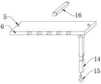
2、本实用新型中,通过设置的一号吊板与活动吊杆,便于勾住箱式变电站,这里,将一号吊板与二号吊板插入到升降架的内部,并用定位插板进行固定,一号吊板与二号吊板在升降架的内部位置可以调节,可以根据像是变电站的尺寸调整两组活动吊杆之间的距离,为了避免一号吊板上面的活动吊杆移动受限,在二号吊板上面开车辅助活动槽,如附图所示,设置的定位插槽则用于定位插板穿过升降架将一号吊板与二号吊板固定在升降架的内部。2. In this utility model, it is convenient to hook the box-type substation through the No. 1 hanging plate and the movable boom. Fixed, the No. 1 hanging plate and the No. 2 hanging plate can be adjusted in the inner position of the lifting frame, and the distance between the two sets of movable booms can be adjusted according to the size of the substation, in order to avoid the moving of the movable boom on the No. 1 hanging plate Limited, the driving auxiliary activity slot on the No. 2 hanging plate, as shown in the attached figure, the positioning slot is used for positioning the inserting plate to pass through the lifting frame to fix the No. 1 hanging plate and the No. 2 hanging plate on the lifting frame. internal.
附图说明Description of drawings
图1是本实用新型的整体结构示意图;Fig. 1 is the overall structural representation of the utility model;
图2是本实用新型的电动机与螺纹管的结构示意图;Fig. 2 is the structural representation of electric motor and threaded pipe of the present utility model;
图3是本实用新型的一号吊板与定位插板的结构示意图;Fig. 3 is a structural schematic diagram of No. 1 hanging plate and positioning inserting plate of the present utility model;
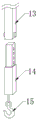
图4是本实用新型的活动吊杆与空心架的结构示意图。Fig. 4 is a schematic structural view of the movable suspender and the hollow frame of the present invention.
图中:1、吊架;2、传动螺杆;3、电动机;4、装载扣板;5、限位插杆;6、一号吊板;7、螺帽;8、平衡滑杆;9、螺纹管;10、升降架;11、辅助活动槽;12、二号吊板;13、空心架;14、活动吊杆;15、钩环;16、定位插板;17、定位插槽。In the figure: 1. Hanger; 2. Transmission screw; 3. Motor; 4. Loading buckle; 5. Limit insertion rod; Threaded pipe; 10, lifting frame; 11, auxiliary movable groove; 12, No. 2 hanging plate; 13, hollow frame; 14, movable suspender; 15, shackle;
具体实施方式Detailed ways
为使本实用新型实现的技术手段、创作特征、达成目的与功效易于明白了解,下面结合具体实施方式,进一步阐述本实用新型。In order to make the technical means, creative features, goals and effects achieved by the utility model easy to understand, the utility model will be further elaborated below in conjunction with specific embodiments.
如图1-4所示,一种美式箱变吊装结构,包括吊架1,吊架1的上端外表面设置有一组电动机3;As shown in Figure 1-4, an American-style box-type transformer hoisting structure includes a
吊架1的两侧外表面对称设置有两组装载扣板4,电动机3的下端外表面设置有一组传动螺杆2,吊架1的下端设置有升降架10,升降架10的上端外表面设置有螺纹管9,升降架10与吊架1之间对称设置有四组平衡滑杆8,每组平衡滑杆8均位于吊架1的内壁;Two sets of
每组平衡滑杆8的上端外表面均设置有一组螺帽7。A set of
升降架10的内部对称设置有一组一号吊板6与一组二号吊板12,二号吊板12位于一号吊板6的下端,一号吊板6与二号吊板12的上端外表面均对称设置有两组限位插杆5,二号吊板12的一侧内表面设置有辅助活动槽11,一号吊板6与二号吊板12的内部均设置有多组定位插槽17,一号吊板6与升降架10之间设置有一组定位插板16,二号吊板12与升降架10之间同样设置有一组定位插板16,一号吊板6与二号吊板12的下端外表面均设置有一组空心架13,空心架13的内壁设置有活动吊杆14,活动吊杆14的下端外表面设置有钩环15。The interior of the
平衡滑杆8与吊架1之间设置有滑动槽,平衡滑杆8的外壁通过滑动槽与吊架1的内壁滑动连接。A slide groove is provided between the
螺纹管9与传动螺杆2之间设置有连接螺纹,螺纹管9的内壁通过连接螺纹与传动螺杆2的外壁活动连接。A connecting thread is arranged between the threaded
活动吊杆14与空心架13之间设置有定位螺栓,活动吊杆14的外壁通过定位螺栓与空心架13的内壁可拆卸连接。A positioning bolt is arranged between the
定位插板16与升降架10之间设置有插孔,定位插板16通过插孔与升降架10的内壁可拆卸连接。A socket is provided between the
具体实施例一:设置的螺帽7用于避免平衡滑杆8从吊架1上面掉落。Specific embodiment one: the provided
具体实施例二:设置的活动吊杆14可以在空心架13上面进行位置调节,根据变电站的边侧吊环位置灵活调节。Specific embodiment two: the set
需要说明的是,本实用新型为一种美式箱变吊装结构,使用时,设置的传动螺杆2与螺纹管9,便于带动升降架10上升与下降,这里将吊架1安装到吊车上面,当需要对箱式变电站进行吊装的时候,当需要带动升降架10上升与下降的时候,控制电动机3带动传动螺杆2转动,由于四组平衡滑杆8限制了升降架10的转动,因此传动螺杆2会在螺纹管9的内壁转动,根据螺纹传动结构,则螺纹管9会在传动螺杆2上面发生位移,从而带动升降架10上升与下降,方便将箱式变电站进行初步吊起;设置的一号吊板6与活动吊杆14,便于勾住箱式变电站,这里,将一号吊板6与二号吊板12插入到升降架10的内部,并用定位插板16进行固定,一号吊板6与二号吊板12在升降架10的内部位置可以调节,可以根据像是变电站的尺寸调整两组活动吊杆14之间的距离,为了避免一号吊板6上面的活动吊杆14移动受限,在二号吊板12上面开车辅助活动槽11,如附图所示,设置的定位插槽17则用于定位插板16穿过升降架10将一号吊板6与二号吊板12固定在升降架10的内部。It should be noted that the utility model is a hoisting structure of an American-style box transformer. When in use, the
以上显示和描述了本实用新型的基本原理和主要特征和本实用新型的优点。本行业的技术人员应该了解,本实用新型不受上述实施例的限制,上述实施例和说明书中描述的只是说明本实用新型的原理,在不脱离本实用新型精神和范围的前提下,本实用新型还会有各种变化和改进,这些变化和改进都落入要求保护的本实用新型范围内。本实用新型要求保护范围由所附的权利要求书及其等效物界定。The basic principles and main features of the present utility model and the advantages of the present utility model have been shown and described above. Those skilled in the art should understand that the utility model is not limited by the above-mentioned embodiments. The above-mentioned embodiments and descriptions only illustrate the principle of the utility model. Without departing from the spirit and scope of the utility model, the utility model The new model also has various changes and improvements, and these changes and improvements all fall within the scope of the claimed utility model. The scope of protection required by the utility model is defined by the appended claims and their equivalents.
Claims (6)
Priority Applications (1)
| Application Number | Priority Date | Filing Date | Title |
|---|---|---|---|
| CN202222648751.7U CN218520871U (en) | 2022-10-08 | 2022-10-08 | American case becomes hoisting structure |
Applications Claiming Priority (1)
| Application Number | Priority Date | Filing Date | Title |
|---|---|---|---|
| CN202222648751.7U CN218520871U (en) | 2022-10-08 | 2022-10-08 | American case becomes hoisting structure |
Publications (1)
| Publication Number | Publication Date |
|---|---|
| CN218520871U true CN218520871U (en) | 2023-02-24 |
Family
ID=85249188
Family Applications (1)
| Application Number | Title | Priority Date | Filing Date |
|---|---|---|---|
| CN202222648751.7U Expired - Fee Related CN218520871U (en) | 2022-10-08 | 2022-10-08 | American case becomes hoisting structure |
Country Status (1)
| Country | Link |
|---|---|
| CN (1) | CN218520871U (en) |
-
2022
- 2022-10-08 CN CN202222648751.7U patent/CN218520871U/en not_active Expired - Fee Related
Similar Documents
| Publication | Publication Date | Title |
|---|---|---|
| CN201817223U (en) | Suspension device for on-load tapping switches of transformers | |
| CN106904526A (en) | One kind the lifting adjustable General balance beam suspender of span and its application method | |
| CN204434191U (en) | A kind of electric power facility hanging apparatus | |
| CN115973926A (en) | Boom structure of construction elevator | |
| CN207312932U (en) | A kind of wall bushing special hanger | |
| CN117800206B (en) | Overload-preventing hanging structure for tower crane | |
| CN219194276U (en) | Cantilever crane | |
| CN209455923U (en) | Detachable rectangular elements hoisting structure | |
| CN216235770U (en) | Auxiliary device is used in water conservancy construction pipeline installation | |
| CN218734685U (en) | A communication equipment base station installation auxiliary equipment for 5G construction | |
| CN209988998U (en) | A special positioning and installation device for electrical engineering and its automation | |
| CN216918404U (en) | Counterweight device for crane and crane | |
| CN215580038U (en) | Live working distribution network overhauls with laborsaving kit | |
| CN214527607U (en) | Wind-powered electricity generation wheel hub ring flange psammitolite assembly fixture | |
| CN218434591U (en) | Safety protection device for hoisting machinery | |
| CN221440110U (en) | Hoisting auxiliary device for electromechanical installation of building | |
| CN209455952U (en) | A kind of device that can disposably replace tup | |
| CN220056065U (en) | Pendant frock for steel construction with adjustable | |
| CN217102742U (en) | A kind of hoisting equipment for flat aluminum alloy | |
| CN221821670U (en) | Rail transit U-shaped beam steel bar lifting appliance | |
| CN221662427U (en) | A pipeline hoisting device for subway stations | |
| CN223445174U (en) | Auxiliary equipment for hoisting construction of large-plate decorative materials | |
| CN220165605U (en) | Lifting device for assembled building | |
| CN222743870U (en) | Hoisting device for installing I-steel for fish pond installation | |
| CN221720277U (en) | A spindle assembly assembly tool |
Legal Events
| Date | Code | Title | Description |
|---|---|---|---|
| GR01 | Patent grant | ||
| GR01 | Patent grant | ||
| CF01 | Termination of patent right due to non-payment of annual fee | ||
| CF01 | Termination of patent right due to non-payment of annual fee |
Granted publication date: 20230224 |