CN218513196U - Oil-resistant flexible winding flexible cable - Google Patents
Oil-resistant flexible winding flexible cable Download PDFInfo
- Publication number
- CN218513196U CN218513196U CN202222454308.6U CN202222454308U CN218513196U CN 218513196 U CN218513196 U CN 218513196U CN 202222454308 U CN202222454308 U CN 202222454308U CN 218513196 U CN218513196 U CN 218513196U
- Authority
- CN
- China
- Prior art keywords
- layer
- oil
- core
- resistant
- conductor
- Prior art date
- Legal status (The legal status is an assumption and is not a legal conclusion. Google has not performed a legal analysis and makes no representation as to the accuracy of the status listed.)
- Active
Links
- 238000004804 winding Methods 0.000 title claims abstract description 12
- 229920001971 elastomer Polymers 0.000 claims abstract description 16
- 238000001125 extrusion Methods 0.000 claims abstract description 14
- 229920006231 aramid fiber Polymers 0.000 claims abstract description 13
- 230000001050 lubricating effect Effects 0.000 claims abstract description 9
- 238000010521 absorption reaction Methods 0.000 claims abstract description 6
- 230000003014 reinforcing effect Effects 0.000 claims abstract description 6
- 239000010410 layer Substances 0.000 claims description 167
- 239000004020 conductor Substances 0.000 claims description 34
- RYGMFSIKBFXOCR-UHFFFAOYSA-N Copper Chemical compound [Cu] RYGMFSIKBFXOCR-UHFFFAOYSA-N 0.000 claims description 13
- 229910052802 copper Inorganic materials 0.000 claims description 11
- 239000010949 copper Substances 0.000 claims description 11
- 229920001084 poly(chloroprene) Polymers 0.000 claims description 11
- 238000009413 insulation Methods 0.000 claims description 8
- 230000000903 blocking effect Effects 0.000 claims description 7
- -1 polytetrafluoroethylene Polymers 0.000 claims description 6
- 229920001343 polytetrafluoroethylene Polymers 0.000 claims description 6
- 239000004810 polytetrafluoroethylene Substances 0.000 claims description 6
- 238000011049 filling Methods 0.000 claims description 5
- 239000012790 adhesive layer Substances 0.000 claims description 3
- 208000037656 Respiratory Sounds Diseases 0.000 abstract description 15
- 230000008595 infiltration Effects 0.000 abstract description 6
- 238000001764 infiltration Methods 0.000 abstract description 6
- 239000012530 fluid Substances 0.000 abstract description 5
- 238000003825 pressing Methods 0.000 abstract 1
- 230000000694 effects Effects 0.000 description 8
- 238000009941 weaving Methods 0.000 description 5
- 238000005452 bending Methods 0.000 description 3
- 230000032683 aging Effects 0.000 description 2
- 238000005253 cladding Methods 0.000 description 2
- 229920003020 cross-linked polyethylene Polymers 0.000 description 2
- 239000004703 cross-linked polyethylene Substances 0.000 description 2
- 230000005672 electromagnetic field Effects 0.000 description 2
- 239000003292 glue Substances 0.000 description 2
- 239000000314 lubricant Substances 0.000 description 2
- 229920000181 Ethylene propylene rubber Polymers 0.000 description 1
- 239000004734 Polyphenylene sulfide Substances 0.000 description 1
- 239000004809 Teflon Substances 0.000 description 1
- 229920006362 Teflon® Polymers 0.000 description 1
- 230000006978 adaptation Effects 0.000 description 1
- 230000004888 barrier function Effects 0.000 description 1
- 230000009286 beneficial effect Effects 0.000 description 1
- 230000005540 biological transmission Effects 0.000 description 1
- 239000011248 coating agent Substances 0.000 description 1
- 239000011247 coating layer Substances 0.000 description 1
- 238000000576 coating method Methods 0.000 description 1
- 238000005336 cracking Methods 0.000 description 1
- 230000007547 defect Effects 0.000 description 1
- 238000010586 diagram Methods 0.000 description 1
- 230000007613 environmental effect Effects 0.000 description 1
- 238000002955 isolation Methods 0.000 description 1
- 239000002346 layers by function Substances 0.000 description 1
- 239000000463 material Substances 0.000 description 1
- 239000011159 matrix material Substances 0.000 description 1
- 238000002156 mixing Methods 0.000 description 1
- 230000004048 modification Effects 0.000 description 1
- 238000012986 modification Methods 0.000 description 1
- 229920003023 plastic Polymers 0.000 description 1
- 239000004033 plastic Substances 0.000 description 1
- 229920000728 polyester Polymers 0.000 description 1
- 229920000642 polymer Polymers 0.000 description 1
- 229920000098 polyolefin Polymers 0.000 description 1
- 229920000069 polyphenylene sulfide Polymers 0.000 description 1
- 239000011241 protective layer Substances 0.000 description 1
- 230000008054 signal transmission Effects 0.000 description 1
Images



Classifications
-
- Y—GENERAL TAGGING OF NEW TECHNOLOGICAL DEVELOPMENTS; GENERAL TAGGING OF CROSS-SECTIONAL TECHNOLOGIES SPANNING OVER SEVERAL SECTIONS OF THE IPC; TECHNICAL SUBJECTS COVERED BY FORMER USPC CROSS-REFERENCE ART COLLECTIONS [XRACs] AND DIGESTS
- Y02—TECHNOLOGIES OR APPLICATIONS FOR MITIGATION OR ADAPTATION AGAINST CLIMATE CHANGE
- Y02A—TECHNOLOGIES FOR ADAPTATION TO CLIMATE CHANGE
- Y02A30/00—Adapting or protecting infrastructure or their operation
- Y02A30/14—Extreme weather resilient electric power supply systems, e.g. strengthening power lines or underground power cables
Landscapes
- Insulated Conductors (AREA)
Abstract
The utility model relates to a flexible winding cable technical field specifically provides an oil-resistant type flexible winding flexible cable, include: the cable comprises a cable core, an oil-blocking layer and an outer sheath, wherein the oil-blocking layer comprises a longitudinal oil-blocking layer, a radial oil-blocking layer, a lubricating layer and a reinforcing layer which are sequentially coated from inside to outside, the longitudinal oil-blocking layer comprises oil-absorbing expansion rubber extruded on the outer wall of the cable core, and the reinforcing layer comprises an aramid fiber woven layer; if radial oil blanket appearance crackle and during the oil impregnate of hindering, vertically hinder the oil blanket oil absorption expansion, by radially hindering the inboard of oil blanket and applying pressure to the crackle department that radially hinders the oil blanket, simultaneously, the enhancement layer that aramid fiber silk was woven is spacing to radially hindering the oil blanket outside, avoid radially hindering the oil blanket and take place radial deformation to the outside, at this moment, radially hinder the crackle department of oil blanket and receive the extrusion force, and produce horizontal deformation, make the crackle radially hinder the basic unit shutoff of oil blanket by deformation, avoid further infiltration of fluid.
Description
Technical Field
The utility model relates to a flexible cable technical field of rubber sleeve particularly relates to an oil-resistant flexible winding flexible cable.
Background
The rubber sleeve cable is made of a plurality of strands of fine copper wires as conductors, a functional layer is wound outside a cabled cable core, and then a rubber insulating layer and a rubber sheath are wrapped outside the cable core to form a soft and windable cable.
At present, due to different application fields, environmental working conditions of rubber sleeve cables are different, generally, the rubber sleeve cables are divided into three types, namely light, medium and heavy, on the product structure according to mechanical external force and environment borne by the electric wires and the electric wires, and special requirements are provided for the protection and the performance of the electric wires and the electric wires by combining with specific use environments. For example, in common industrial and agricultural environments, such as port machinery, diesel generators, welders, agricultural machinery, etc., when applied in an oil environment or a multi-oil environment, the oil resistance of the cable is tested, and thus the problems of oil infiltration, aging and cable life are not expected.
In the prior art, a coating layer with an oil-resistant effect is explored and tried to be added in a cable wrapping structure to improve the oil-resistant performance of a cable, for example, an oil-resistant isolation layer is added to improve the overall oil-resistant performance of the cable, or a sheath made of rubber is directly used to be used as an insulating layer and a protective layer. However, during cable use, a single oil resistant barrier layer or jacket layer is susceptible to cracking due to frequent coiling, bending, and harsh outdoor use environments.
SUMMERY OF THE UTILITY MODEL
In view of the defect and not enough that prior art exists, the utility model aims to provide an oil-resistant flexible winding flexible cable can improve the holistic oil resistance of cable to avoid the further infiltration of fluid, reduce fluid infiltration, improve the life-span of cable.
According to the utility model discloses the first aspect of purpose provides an oil-resistant type flexible winding flexible cable, include:
the cable core comprises a plurality of stranded wire cores, including a power wire core, a grounding wire core and a control wire core;
the outer sheath is extruded on the outer side wall of the oil resistance layer;
the oil resistance layer comprises a longitudinal oil resistance layer, a radial oil resistance layer, a lubricating layer and a reinforcing layer which are sequentially coated from inside to outside, and the longitudinal oil resistance layer comprises oil absorption expansion rubber extruded on the outer wall of the cable core;
the enhancement layer includes aramid fiber silk weaving layer, aramid fiber silk weaving layer cladding is at the lubricant film outer wall.
Preferably, the extrusion thickness of the longitudinal oil-blocking layer is 2.0mm-2.5mm.
Preferably, the radial oil-blocking layer comprises a chloroprene rubber base layer extruded on the outer wall of the longitudinal oil-blocking layer and an adhesive layer coated on the chloroprene rubber base layer.
Preferably, the extrusion thickness of the base layer of the radial oil-blocking layer is 1.5mm-2.5mm.
Preferably, the lubricating layer comprises a polytetrafluoroethylene wrapping layer, the polytetrafluoroethylene wrapping layer is wrapped on the outer wall of the radial oil resistance layer, the wrapping covering rate is greater than or equal to 25%, and the number of wrapping layers is 2.
Preferably, the cable core comprises three power wire cores which are tangent to each other in pairs and are twisted with each other, the cable core further comprises a grounding wire core and two control wire cores, the grounding wire core and the two control wire cores are respectively arranged in three cutting seams formed outside the three power wire cores, and filling layers are filled in gaps between adjacent three power wire cores and are wrapped into a circular cross section together with the power wire cores, the grounding wire cores and the control wire cores.
Preferably, the power line core comprises a first conductor and a first insulating layer, the first conductor comprises a plurality of strands of intertwisted tin-plated copper wires, and the first insulating layer is extruded on the outer wall of the first conductor.
Preferably, the ground wire core comprises a second conductor and a second insulating layer, the second conductor comprises a plurality of strands of mutually-stranded tin-plated copper wires, and the second insulating layer is extruded on the outer wall of the second conductor.
Preferably, the control wire core comprises a third conductor and an insulation shielding layer, the third conductor comprises a plurality of strands of mutually-stranded tin-plated copper wires, and the insulation shielding layer is extruded on the outer wall of the third conductor.
Preferably, the insulation shielding layer is a three-layer co-extrusion layer and comprises an inner shielding layer, an insulation layer and an outer shielding layer which are sequentially distributed from inside to outside.
Compared with the prior art, the utility model discloses an oil-resistant type flexible winding flexible cable's showing beneficial effect lies in:
through the outside at the cable core and the inboard setting of oversheath block the oil reservoir, play the effect that blocks oil, improve the holistic oil resistance of cable, if radial block the oil reservoir appear the crackle and when the oil impregnate, vertically block the oil reservoir oil absorption inflation, by radially blocking the inboard of oil reservoir to radially blocking the crackle department in oil reservoir and exert pressure, and simultaneously, the enhancement layer that the aramid fiber was woven carries on spacingly to radially blocking the oil reservoir outside, avoid radially blocking the oil reservoir to take place radial deformation to the outside, at this moment, radially block the crackle department in oil reservoir and receive the extrusion force, and produce horizontal deformation, make the crackle by the radial basic unit shutoff that blocks the oil reservoir of deformation, thereby avoid further infiltration of fluid.
Drawings
The drawings are not intended to be drawn to scale. In the drawings, each identical or nearly identical component that is illustrated in various figures may be represented by a like numeral. For purposes of clarity, not every component may be labeled in every drawing. Embodiments of various aspects of the present invention will now be described, by way of example, with reference to the accompanying drawings.
Fig. 1 is a schematic structural view of the oil-resistant flexible wound flexible cable of the present invention.
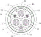
Fig. 2 is a schematic view of a radial cross-sectional structure of the oil-resistant flexible wound flexible cable of the present invention.
Fig. 3 is a schematic distribution diagram of the oil-blocking layer of the oil-resistant flexible wound flexible cable according to the present invention.
Fig. 4 is a schematic structural view of the control wire core of the oil-resistant flexible winding flexible cable of the present invention.
In the figures, the meaning of the individual reference symbols is as follows:
10. a cable core; 11. a power line core; 111. a first conductor; 112. a first insulating layer; 12. a grounding wire core; 121. a second conductor; 122. a second insulating layer; 13. a control wire core; 131. a third conductor; 132. an insulating shield layer; 14. a filling layer; 15. Wrapping a covering; 20. blocking an oil layer; 21. a longitudinal oil blocking layer; 22. a radial oil-blocking layer; 23. a lubricating layer; 24. a reinforcing layer; 30. An outer sheath.
Detailed Description
For a better understanding of the technical content of the present invention, specific embodiments are described below in conjunction with the accompanying drawings.
Referring to fig. 1, the present invention provides an oil-resistant flexible winding flexible cable, which includes a cable core 10, an oil-resistant layer 20 and an outer sheath 30.
In connection with the example shown in fig. 1 and 2, the cable core 10 includes a plurality of stranded cores including a power core 11, a ground core 12 and a control core 13, each of which is formed by twisting a tin-plated copper wire into a strand, wherein the power core 11 serves as power transmission and has a larger cross-sectional area (wire diameter) than the ground core 12 and the control core 13.
In the example shown in fig. 1, three stranded power wire cores 11 are illustrated as an example. The three power wire cores 11 are arranged in a tangent manner in pairs and are mutually twisted with one grounding wire core 12 and two control wire cores 13.
Wherein, earth core 12 and control core 13 are set up respectively in the three joint-cutting that forms in the three electric power sinle silk 11 outside, all fill in the clearance between three electric power sinle silk 11 are adjacent and have filling layer 14 to be lapped the stranding by outside around covering 15 with electric power sinle silk 11, earth core 12 and control core 13 together, form the cross-section and be circular shape cable core structure, the cable core promptly.
Optionally, the filling layer 14 is formed by neoprene extrusion, the cross section of the supporting cable is circular, and the tensile strength of the whole cable is increased.
Further, the wrapping layer 15 is formed by wrapping polyester tapes, the covering rate of the wrapping is 25%, and the number of the wrapping layers is two.
In connection with the examples shown in fig. 1 and 2, the power core 11 comprises a first conductor 111 and a first insulating layer 112. The first conductor 111 includes a plurality of strands of flexible tin-plated copper wires twisted with each other, and a first insulating layer 112 is extruded on the outer wall of the first conductor 111.
Optionally, the first insulating layer 112 is an ethylene propylene rubber insulating layer, which has excellent electrical insulating property and corona resistance, can play a good insulating role, has good aging resistance, and can be used at a temperature of below 120 ℃ for a long time to maintain a good insulating effect.
As shown in fig. 1 and fig. 2, the ground wire core 12 includes a second conductor 121 and a second insulating layer 122, the second conductor 121 is formed by twisting a plurality of strands of tinned copper wires, and has good conductivity, and the tinned copper wires are relatively soft, so that the second conductor 121 has good flexibility as a whole, and is extruded and fixed through the second insulating layer 122 on the outer surface of the second conductor 121.
Optionally, the second insulating layer 122 is formed by extruding a cross-linked polyethylene material, so that the insulating layer has good insulating property, has excellent bending resistance, can be bent at will, cannot be cracked, and ensures an insulating effect.
As shown in fig. 1 and fig. 4, the control wire core 13 includes a third conductor 131 and an insulating shielding layer 132, the third conductor 131 includes a plurality of strands of twisted tinned copper wires, the insulating shielding layer 132 is wrapped around the outer wall of the third conductor 131, and has good conductivity, and the tinned copper wire is softer, so that the third conductor 131 has good flexibility.
Further, the insulation shielding layer 132 is a three-layer co-extrusion layer, which includes an inner shielding layer, an insulation layer and an outer shielding layer that are sequentially distributed from inside to outside. As an alternative example, the inner shielding layer and the outer shielding layer are made of commercial semiconductive polyolefin, the insulating layer is made of commercial crosslinked polyethylene, and the electromagnetic field is shielded by the inner shielding layer and the outer shielding layer, so as to reduce the influence of the electromagnetic field on the signal transmission of the third conductor 131.
Referring to fig. 1, 2 and 3, the oil-blocking layer 20 is coated on the outer sidewall of the cable core 10.
As an optional embodiment, the oil-blocking layer 20 includes a longitudinal oil-blocking layer 21, a radial oil-blocking layer 22, a lubricating layer 23, and a reinforcing layer 24 sequentially coated from inside to outside, the longitudinal oil-blocking layer 21 includes oil-absorbing expandable rubber extruded on the outer wall of the cable core 10, and when the radial oil-blocking layer 22 is cracked and leaks oil, the oil-absorbing expandable rubber absorbs oil to expand, so as to prevent the oil from further extending along the axial direction of the cable.
Alternatively, the oil-absorbing expanded rubber is prepared by taking high-elasticity rubber as a matrix and adding an oil-absorbing component for blending, such as a commercial oil-absorbing expanded rubber strip.
As an alternative example, the squeeze thickness of the longitudinal oil-blocking layer 21 is 2.0mm to 2.5mm, and in order to ensure a good oil-blocking effect, it is preferable that the squeeze thickness of the longitudinal oil-blocking layer 21 is 2.5mm.
As an alternative example, the radial oil-resistant layer 22 includes a neoprene base layer extruded on the outer wall of the longitudinal oil-resistant layer 21 and an adhesive layer coated on the neoprene base layer. The chloroprene rubber base layer has good oil resistance, and the oil resistance effect of the radial oil resistance layer 22 is further improved by coating the rubber polymer layer on the chloroprene rubber base layer.
As an alternative example, the glue layer is a polyphenylene sulfide plastic glue layer.
As an optional example, the base layer extrusion thickness of the radial oil-blocking layer 22 is 1.5mm to 2.5mm, so as to ensure a good oil-blocking effect, and preferably, the base layer extrusion thickness of the radial oil-blocking layer 22 is 2 mm to 2.5mm.
Optionally, the lubricating layer 23 comprises a teflon wrapping.
As an optional example, the polytetrafluoroethylene wrapping layer is coated on the outer wall of the radial oil-blocking layer 22, the wrapping coverage rate is greater than or equal to 25%, and the number of wrapping layers is 2. Therefore, in the embodiment of the utility model, polytetrafluoroethylene is lower around the coefficient of surface friction of package, radially hinders between oil reservoir 22 and enhancement layer 24 through the setting, can protect radially hindering oil reservoir 22, avoids leading to the enhancement layer 24 radially to hinder oil reservoir 22 and grind through twisting back because of the cable bending.
Combine fig. 1 and fig. 3 to show, enhancement layer 24 is set up to the weaving layer, and enhancement layer 24 includes aramid fiber silk weaving layer, and the cladding of aramid fiber silk weaving layer is at 23 outer walls of lubricant film, and it is spacing to vertically hinder oil layer 21 and radially hinder oil layer 22 through the enhancement layer 24 that aramid fiber silk was woven, and simultaneously, the holistic tensile strength of cable can effectively be increased to the enhancement layer 24 that aramid fiber silk was woven.
So, when vertically hindering oil reservoir 21 oil absorption inflation, exert pressure to the crackle department that radially hinders oil reservoir 22 by the inboard that radially hinders oil reservoir 22, simultaneously, enhancement layer 24 that aramid fiber woven carries on spacingly to radially hindering oil reservoir 22, avoids radially hindering oil reservoir 22 to take place radial deformation to the outside, and at this moment, radially hinder oil reservoir 22's crackle department and receive the extrusion force to produce horizontal deformation, make the crackle by the radial basic unit shutoff that hinders oil reservoir 22 of deformation.
As shown in fig. 1 and 2, the outer sheath 30 is wrapped on the outer side wall of the oil-blocking layer 20 in an extruded manner, the outer sheath 30 is formed by wrapping a neoprene rubber in an extruded manner, and the neoprene rubber has good mechanical properties, good oil resistance and improved oil resistance of the cable.
Combine above embodiment, through the outside at cable core 10 and oversheath 30 inboard setting hinder oil layer 20, play the effect of hindering oil, improve the holistic oil resistance of cable, when radially hindering oil layer 22 appearance crackle and oil impregnate, vertically hinder oil layer 21 oil absorption inflation, the inboard of radially hindering oil layer 22 exerts pressure to the crackle department of radially hindering oil layer 22 by radially hindering oil layer 22, and simultaneously, the enhancement layer 24 that aramid fiber woven carries on spacingly to radially hindering the oil layer 22 outside, avoid radially hindering oil layer 22 to take place radial deformation to the outside, at this moment, radially hinder oil layer 22's crackle department receives the extrusion force, and produce horizontal deformation, make the crackle by the radial basic unit shutoff that hinders oil layer 22 of deformation, thereby avoid the further infiltration of fluid.
Although the present invention has been described with reference to the preferred embodiments, it is not intended to limit the present invention. The present invention is intended to cover by those skilled in the art various modifications and adaptations of the invention without departing from the spirit and scope of the invention. Therefore, the protection scope of the present invention is subject to the claims.
Claims (10)
1. An oil-resistant flexible coiled flexible cable, comprising:
the cable core (10) comprises a plurality of stranded wire cores, including a power wire core (11), a grounding wire core (12) and a control wire core (13);
the oil blocking layer (20) is coated on the outer side wall of the cable core (10);
the outer sheath (30) is extruded on the outer side wall of the oil-blocking layer (20);
the oil resistance layer (20) comprises a longitudinal oil resistance layer (21), a radial oil resistance layer (22), a lubricating layer (23) and a reinforcing layer (24) which are sequentially coated from inside to outside, and the longitudinal oil resistance layer (21) comprises oil absorption expansion rubber extruded on the outer wall of the cable core (10);
the reinforced layer (24) comprises an aramid fiber woven layer, and the aramid fiber woven layer is coated on the outer wall of the lubricating layer (23).
2. The oil resistant flexible coiled flexible cable according to claim 1, characterized in that the longitudinal oil-resistant layer (21) has an extrusion thickness of 2.0mm to 2.5mm.
3. The oil-resistant flexible wound flexible cable according to claim 1, wherein the radial oil-resistant layer (22) comprises a neoprene base layer extruded on the outer wall of the longitudinal oil-resistant layer (21) and an adhesive layer coated on the neoprene base layer.
4. The oil resistant flexible coiled flexible cable according to claim 1, wherein the base layer extrusion thickness of the radial oil resistant layer (22) is 1.5mm to 2.5mm.
5. The oil-resistant flexible winding flexible cable according to claim 1, wherein the lubricating layer (23) comprises a polytetrafluoroethylene wrapping layer, the polytetrafluoroethylene wrapping layer is coated on the outer wall of the radial oil resistance layer (22), the wrapping and covering rate is not less than 25%, and the number of the wrapping layers is two.
6. The oil-resistant flexible winding flexible cable according to any one of claims 1 to 5, wherein the cable core (10) comprises three power cores (11) which are tangent to each other in pairs and twisted with each other, the cable core (10) further comprises a ground core (12) and two control cores (13), the ground core (12) and the two control cores (13) are respectively arranged in three kerfs formed outside the three power cores (11), gaps between the three adjacent power cores (11) are filled with a filling layer (14), and the three kerfs, the power cores (11), the ground core (12) and the control cores (13) are wrapped with a wrapping layer (15) to form a circular cross section.
7. The oil-resistant flexible coiled flexible cable according to claim 6, wherein the power wire core (11) comprises a first conductor (111) and a first insulating layer (112), the first conductor (111) comprises a plurality of strands of intertwisted tin-plated copper wires, and the first insulating layer (112) is extruded on the outer wall of the first conductor (111).
8. The oil-resistant flexible coiled flexible cable according to claim 6, wherein the ground core (12) comprises a second conductor (121) and a second insulating layer (122), the second conductor (121) comprises a plurality of strands of twisted tin-plated copper wires, and the second insulating layer (122) is extruded on the outer wall of the second conductor (121).
9. The oil-resistant flexible coiled flexible cable according to claim 6, wherein the control wire core (13) comprises a third conductor (131) and an insulating shielding layer (132), the third conductor (131) comprises a plurality of strands of twisted tin-plated copper wires, and the insulating shielding layer (132) is extruded on the outer wall of the third conductor (131).
10. The oil-resistant flexible coiled flexible cable according to claim 6, wherein the insulation shielding layer (132) is a three-layer co-extrusion layer comprising an inner shielding layer, an insulation layer and an outer shielding layer which are sequentially distributed from inside to outside.
Priority Applications (1)
| Application Number | Priority Date | Filing Date | Title |
|---|---|---|---|
| CN202222454308.6U CN218513196U (en) | 2022-09-16 | 2022-09-16 | Oil-resistant flexible winding flexible cable |
Applications Claiming Priority (1)
| Application Number | Priority Date | Filing Date | Title |
|---|---|---|---|
| CN202222454308.6U CN218513196U (en) | 2022-09-16 | 2022-09-16 | Oil-resistant flexible winding flexible cable |
Publications (1)
| Publication Number | Publication Date |
|---|---|
| CN218513196U true CN218513196U (en) | 2023-02-21 |
Family
ID=85214810
Family Applications (1)
| Application Number | Title | Priority Date | Filing Date |
|---|---|---|---|
| CN202222454308.6U Active CN218513196U (en) | 2022-09-16 | 2022-09-16 | Oil-resistant flexible winding flexible cable |
Country Status (1)
| Country | Link |
|---|---|
| CN (1) | CN218513196U (en) |
-
2022
- 2022-09-16 CN CN202222454308.6U patent/CN218513196U/en active Active
Similar Documents
| Publication | Publication Date | Title |
|---|---|---|
| EP3111452B1 (en) | Electrical cables with strength elements | |
| CN107358997B (en) | Multi-core photoelectric composite watertight cable for deep sea system | |
| CN210006533U (en) | direct current submarine cable for deep sea | |
| CN116646120A (en) | Floating cable for self-buoyancy water surface robot and manufacturing method thereof | |
| CN112002462A (en) | High-low temperature-resistant anti-interference comprehensive flexible cable for unmanned aerial vehicle | |
| CN202454305U (en) | Metal sheath type cable for oil platform | |
| CN202549448U (en) | Middle-high-voltage power and information monitoring comprehensive cable for ocean engineering | |
| CN210692140U (en) | Cold-resistant and anti-corrosion umbilical cable for moving underwater direct current system | |
| CN210865664U (en) | High-flexibility bending-resistant marine towline cable | |
| CN107978386B (en) | Flexible tensile control cable for intelligent equipment and manufacturing method thereof | |
| CN214956123U (en) | Medium-voltage waterproof power cable | |
| CN215815309U (en) | Crosslinked polyethylene insulated aluminum wire armored low-smoke halogen-free sheath medium-voltage cable | |
| CN214753063U (en) | Compound towing cable for underwater photoelectric transmission system | |
| CN214624471U (en) | Flexible Wind Control Cable | |
| CN210896707U (en) | Stretch-proof flame-retardant water-blocking cable | |
| CN108597660A (en) | Suspension cable waterborne | |
| CN117116535A (en) | Water-blocking conductors and submarine cables | |
| CN210349348U (en) | Fill electric pile cable | |
| CN202549469U (en) | Medium-high voltage power cable used for ocean engineering | |
| CN107516554A (en) | A high-strength digital communication cable | |
| CN218497807U (en) | Tensile type winding cable | |
| EP2259270B1 (en) | Cable element, data transmission cable, method for manufacturing and use of data transmission cable. | |
| CN217521780U (en) | Cable structure | |
| CN220895243U (en) | High-performance medium-voltage power cable | |
| CN207217152U (en) | A kind of high intensity cable for digital communication |
Legal Events
| Date | Code | Title | Description |
|---|---|---|---|
| GR01 | Patent grant | ||
| GR01 | Patent grant |