CN218497862U - Disk frame winch for producing conducting wire - Google Patents
Disk frame winch for producing conducting wire Download PDFInfo
- Publication number
- CN218497862U CN218497862U CN202222667519.8U CN202222667519U CN218497862U CN 218497862 U CN218497862 U CN 218497862U CN 202222667519 U CN202222667519 U CN 202222667519U CN 218497862 U CN218497862 U CN 218497862U
- Authority
- CN
- China
- Prior art keywords
- fixed mounting
- roof
- driving shaft
- lower extreme
- protection casing
- Prior art date
- Legal status (The legal status is an assumption and is not a legal conclusion. Google has not performed a legal analysis and makes no representation as to the accuracy of the status listed.)
- Active
Links
- 238000004519 manufacturing process Methods 0.000 claims abstract description 13
- 230000005540 biological transmission Effects 0.000 claims description 23
- 238000007789 sealing Methods 0.000 claims description 14
- 230000001681 protective effect Effects 0.000 claims description 6
- 229910000831 Steel Inorganic materials 0.000 claims description 5
- 239000010959 steel Substances 0.000 claims description 5
- 230000008878 coupling Effects 0.000 claims 2
- 238000010168 coupling process Methods 0.000 claims 2
- 238000005859 coupling reaction Methods 0.000 claims 2
- 238000005065 mining Methods 0.000 claims 1
- 230000000694 effects Effects 0.000 abstract description 6
- 230000002633 protecting effect Effects 0.000 abstract description 2
- 238000000034 method Methods 0.000 description 7
- 230000009471 action Effects 0.000 description 4
- 230000008569 process Effects 0.000 description 4
- 230000000712 assembly Effects 0.000 description 2
- 238000000429 assembly Methods 0.000 description 2
- 230000002411 adverse Effects 0.000 description 1
- 238000013475 authorization Methods 0.000 description 1
- 230000009286 beneficial effect Effects 0.000 description 1
- 230000008859 change Effects 0.000 description 1
- 230000002950 deficient Effects 0.000 description 1
- 238000010586 diagram Methods 0.000 description 1
- 239000000463 material Substances 0.000 description 1
- 230000007246 mechanism Effects 0.000 description 1
- 238000003825 pressing Methods 0.000 description 1
- 238000004804 winding Methods 0.000 description 1
Images


Landscapes
- Ropes Or Cables (AREA)
Abstract
The utility model discloses a wire production is with dish frame winch, which comprises a base, the upper end fixed surface of base installs dish frame winch main part, the upper portion of dish frame winch main part is provided with the arch protection casing, the upper portion of arch protection casing is provided with the roof, the four corners fixed mounting of roof lower extreme surface has the bracing piece, the lower extreme surface of bracing piece is connected with the upper end fixed surface of base, be provided with lifting unit between arch protection casing and the roof, just lifting unit's quantity is two sets of, the left and right sides fixed mounting of roof lower extreme surface has the guide arm, the upper portion fixed mounting of arch protection casing both ends surface has the connecting block, the one end fixed surface of connecting block installs the sliding sleeve. A wire production is with dish frame winch, possess certain protecting effect, when avoiding taking place the broken string, cracked wire gets rid of the frame winch under inertial effect on the drum, increases advantages such as security.
Description
Technical Field
The utility model relates to a wire production facility technical field specifically is a wire production is with dish frame winch.
Background
The manufacturing equipment of the multi-strand integrated cable is a frame stranding machine, a plurality of strands of wires fixed on the frame stranding machine are twisted by the rotation of the frame stranding machine, and a spiral single-strand wire taking the center of the cable as an axis is formed under the pressing of a polycrystalline die, in the prior art, in a Chinese patent document with an authorization publication number of CN207353020U, a frame stranding machine driving mechanism is described, an output shaft of a torque motor is directly connected with a central shaft of the frame stranding machine in a transmission manner, a gearbox is omitted, mechanical friction is reduced, materials and parts are saved, and the cost is saved; the alternating-current frequency converter has a stepless speed regulation function, the universality of the machine is strong, and the machine does not need to be replaced due to the change of production requirements.
However, the reel frame stranding machine for producing the wires is not provided with a protection structure, if the wires are broken, the corresponding wire loading reels do not have traction force and cannot rotate to pay off the wires, the number of the wires wound together is reduced, the cables are defective products, the machine must be stopped in time so as to avoid producing products with unqualified quality, and meanwhile, when the wires are broken, the broken wires on the wire loading reels are thrown off from the frame stranding machine under the action of inertia, so that surrounding personnel are easily injured, and certain adverse effects are brought to the using process of people.
SUMMERY OF THE UTILITY MODEL
Technical problem to be solved
The utility model provides a not enough to prior art, the utility model provides a wire production is with dish frame winch possesses certain protecting effect, when avoiding taking place the broken string, cracked wire gets rid of the frame hinge machine of departure under inertial effect on the dress drum, increases advantages such as security, can effectively solve the problem in the background art.
(II) technical scheme
In order to achieve the above purpose, the utility model adopts the following technical scheme: the utility model provides a wire production is with dish frame winch, includes the base, the upper end surface fixed mounting of base has dish frame winch main part, the upper portion of dish frame winch main part is provided with the arch protection casing, the upper portion of arch protection casing is provided with the roof, the four corners fixed mounting of roof lower extreme surface has the bracing piece, the lower extreme surface of bracing piece is connected with the upper end surface fixed connection of base, be provided with lifting unit between arch protection casing and the roof, just lifting unit's quantity is two sets of, the left and right sides fixed mounting of roof lower extreme surface has the guide arm, the upper portion fixed mounting of arch protection casing both ends surface has the connecting block, the one end surface fixed mounting of connecting block has the sliding sleeve, lifting unit includes transmission case, servo motor, driven shaft, wire reel, mount, rings, wire rope, driving shaft, worm and worm wheel, just servo motor fixed mounting is in the left and right sides at roof upper end surface middle part, transmission case fixed mounting is in the left and right sides at roof lower extreme surface middle part.
Preferably, the mount is located one side of transmission case, just the upper end surface of mount and the lower extreme surface of roof, the wire reel is located the lower part of mount, wire rope twines in the outer wall of wire reel, is convenient for drive arch protection casing and goes up and down.
Preferably, rings fixed mounting is in the left and right sides of arch protection casing upper end surface, wire rope's one end surface and rings fixed connection, be sliding connection between the outer wall of sliding sleeve and guide arm, increase the stability that the arch protection casing goes up and down.
Preferably, worm wheel are located the inside of transmission case, the driven shaft runs through the wire reel, the outer wall of driven shaft one end is located the inside of transmission case, just worm wheel fixed mounting is in the outer wall of driven shaft one end, the driving shaft is located servo motor's lower extreme surface, worm fixed mounting is in the outer wall of driving shaft lower part, is convenient for drive the wire reel and rotates.
Preferably, a sealing bearing is arranged between the driven shaft and the fixing frame, and the driven shaft is movably connected with the fixing frame through the sealing bearing, so that the stability is improved.
Preferably, a sealing bearing is arranged between the driving shaft and the top plate, the driving shaft is movably connected with the top plate through the sealing bearing, the sealing bearing is arranged between the driving shaft, the driven shaft and the transmission case, the driving shaft and the driven shaft are movably connected with the transmission case through the sealing bearing, the worm and the worm wheel are meshed with each other, a coupler is arranged between the driving shaft and the servo motor, and the outer surface of the upper end of the driving shaft is fixedly connected with the outer surface of the lower end of the servo motor through the coupler, so that the stability is improved.
(III) advantageous effects
Compared with the prior art, the utility model provides a wire production is with dish frame winch possesses following beneficial effect:
1. this wire production is with dish frame winch through the arch protection casing that sets up, is convenient for carry out the cage to the part of dish frame winch main part center hank, increases the protectiveness, when avoiding taking place the broken string, and cracked wire gets rid of the frame winch that flies off under inertial effect on the dress drum, increases the security.
2. This wire production is with dish frame winch through the lifting unit who sets up, is convenient for drive arch protection casing and goes up and down.
Drawings
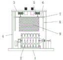
Fig. 1 is the overall structure schematic diagram of the disc frame twisting machine for producing wires of the present invention.
Fig. 2 is a schematic view of a local structure of the disc frame strander for producing wires of the present invention.
Fig. 3 is a schematic view of a local structure of a lifting component in a disc frame winch for producing a wire of the present invention.
In the figure: 1. a base; 2. a disc frame winch body; 3. a top plate; 4. a support bar; 5. a lifting assembly; 6. connecting blocks; 7. a sliding sleeve; 8. a guide bar; 9. an arched shield; 10. a transmission case; 11. a servo motor; 12. a driven shaft; 13. a wire spool; 14. a fixed mount; 15. a hoisting ring; 16. a wire rope; 17. a drive shaft; 18. a worm; 19. a worm gear.
Detailed Description
In order to make the technical means, creation features, achievement purposes and functions of the present invention easy to understand, the present invention is further described below with reference to the following embodiments.
The embodiment is a disc frame twisting machine for producing conducting wires.
As shown in fig. 1-3, the disc frame winch comprises a base 1, a disc frame winch main body 2 is fixedly installed on the outer surface of the upper end of the base 1, an arched protective cover 9 is arranged on the upper portion of the disc frame winch main body 2, a top plate 3 is arranged on the upper portion of the arched protective cover 9, support rods 4 are fixedly installed at four corners of the outer surface of the lower end of the top plate 3, the outer surface of the lower end of each support rod 4 is fixedly connected with the outer surface of the upper end of the base 1, lifting assemblies 5 are arranged between the arched protective covers 9 and the top plate 3, the number of the lifting assemblies 5 is two, guide rods 8 are fixedly installed on the left side and the right side of the outer surface of the lower end of the top plate 3, connecting blocks 6 are fixedly installed on the upper portions of the outer surfaces of the two ends of the arched protective cover 9, sliding sleeves 7 are fixedly installed on the outer surface of one end of each connecting block 6, each lifting assembly 5 comprises a transmission case 10, a servo motor 11, a driven shaft 12, a winding disc 13, a fixed frame 14, a hanging ring 15, a steel wire rope 16, a driving shaft 17, a worm 18 and a worm wheel 19, and the transmission case 10 is fixedly installed on the left side and the right side of the middle portion of the outer surface of the upper portion of the lower end of the upper end of the top plate 3.
The fixing frame 14 is positioned at one side of the transmission case 10, the outer surface of the upper end of the fixing frame 14 and the outer surface of the lower end of the top plate 3 are positioned, the wire spool 13 is positioned at the lower part of the fixing frame 14, and the steel wire rope 16 is wound on the outer wall of the wire spool 13; the hoisting rings 15 are fixedly arranged on the left side and the right side of the outer surface of the upper end of the arched protective cover 9, the outer surface of one end of the steel wire rope 16 is fixedly connected with the hoisting rings 15, and the sliding sleeve 7 is in sliding connection with the outer wall of the guide rod 8; the worm 18 and the worm wheel 19 are positioned in the transmission case 10, the driven shaft 12 penetrates through the wire spool 13, the outer wall of one end of the driven shaft 12 is positioned in the transmission case 10, the worm wheel 19 is fixedly installed on the outer wall of one end of the driven shaft 12, the driving shaft 17 is positioned on the outer surface of the lower end of the servo motor 11, and the worm 18 is fixedly installed on the outer wall of the lower portion of the driving shaft 17; a sealing bearing is arranged between the driven shaft 12 and the fixed frame 14, and the driven shaft 12 is movably connected with the fixed frame 14 through the sealing bearing; a sealing bearing is arranged between the driving shaft 17 and the top plate 3, the driving shaft 17 is movably connected with the top plate 3 through the sealing bearing, the sealing bearings are arranged between the driving shaft 17, the driven shaft 12 and the transmission case 10, the driving shaft 17 and the driven shaft 12 are movably connected with the transmission case 10 through the sealing bearings, the worm 18 is meshed with the worm wheel 19, a coupler is arranged between the driving shaft 17 and the servo motor 11, and the outer surface of the upper end of the driving shaft 17 is fixedly connected with the outer surface of the lower end of the servo motor 11 through the coupler.
It should be noted that, the utility model relates to a wire production is with dish frame winch, the lifting unit 5 of setting, when dish frame winch main part 2 carries out the use, the operation through servo motor 11 drives driving shaft 17 and rotates, driving shaft 17 drives worm 18 and rotates, worm 18 and worm wheel 19 intermeshing, make the rotation of worm 18 drive worm wheel 19 and rotate, worm wheel 19 drives driven shaft 12 and rotates, driven shaft 12 drives wire reel 13 and rotates, wire reel 13 carries out the unwrapping wire to wire rope 16, cover the outer wall at dish frame winch main part 2 middle part with arch protection casing 9, play the effect of protection, lifting unit 5 through the setting, be convenient for drive arch protection casing 9 goes up and down, through the guide arm 8 that sets up, it goes up and down along guide arm 8 to drive sliding sleeve 7 through connecting block 6 when arch protection casing 9 goes up and down, increase the stability that arch protection casing 9 goes up and down.
It is noted that, herein, relational terms such as first and second (a, b, etc.) and the like may be used solely to distinguish one entity or action from another entity or action without necessarily requiring or implying any actual such relationship or order between such entities or actions. Also, the terms "comprises," "comprising," or any other variation thereof, are intended to cover a non-exclusive inclusion, such that a process, method, article, or apparatus that comprises a list of elements does not include only those elements but may include other elements not expressly listed or inherent to such process, method, article, or apparatus. Without further limitation, an element defined by the phrase "comprising a … …" does not exclude the presence of another identical element in a process, method, article, or apparatus that comprises the element.
The basic principles and the main features of the invention and the advantages of the invention have been shown and described above. It will be understood by those skilled in the art that the present invention is not limited to the above embodiments, and that the foregoing embodiments and descriptions are provided only to illustrate the principles of the present invention without departing from the spirit and scope of the present invention.
Claims (6)
1. The utility model provides a wire production is with dish frame winch, includes base (1), its characterized in that: the utility model discloses a hydraulic winch for the mining of automobile, including base (1), upper end surface fixed mounting has dish frame winch main part (2), the upper portion of dish frame winch main part (2) is provided with arch protection casing (9), the upper portion of arch protection casing (9) is provided with roof (3), the four corners fixed mounting of roof (3) lower extreme surface has bracing piece (4), the lower extreme surface of bracing piece (4) is connected with the upper end surface fixed connection of base (1), be provided with lifting unit (5) between arch protection casing (9) and roof (3), just the quantity of lifting unit (5) is two sets of, the left and right sides fixed mounting of roof (3) lower extreme surface has guide arm (8), the upper portion fixed mounting of arch protection casing (9) both ends surface has connecting block (6), the one end surface fixed mounting of connecting block (6) has sliding sleeve (7), lifting unit (5) include transmission case (10), servo motor (11), driven shaft (12), wire reel (13), mount (14), rings (15), wire rope (16), driving shaft (17), worm (18) and worm wheel (19), and install in the middle part fixed mounting in the left and right sides of servo motor (3) surface of transmission case (10) lower extreme (10) the left and right sides fixed mounting of roof (10) the middle part surface .
2. The disc frame strander for producing the conducting wire according to claim 1, wherein: the fixing frame (14) is located on one side of the transmission box (10), the outer surface of the upper end of the fixing frame (14) and the outer surface of the lower end of the top plate (3) are located, the wire spool (13) is located on the lower portion of the fixing frame (14), and the steel wire rope (16) is wound on the outer wall of the wire spool (13).
3. The disc frame strander for producing the conducting wire according to claim 1, wherein: rings (15) are fixedly arranged on the left side and the right side of the outer surface of the upper end of the arched protective cover (9), the outer surface of one end of the steel wire rope (16) is fixedly connected with the rings (15), and the sliding sleeve (7) is in sliding connection with the outer wall of the guide rod (8).
4. The disc frame strander for producing the conducting wire according to claim 1, wherein: worm (18), worm wheel (19) are located the inside of transmission case (10), wire reel (13) is run through in driven shaft (12), the outer wall of driven shaft (12) one end is located the inside of transmission case (10), just worm wheel (19) fixed mounting is in the outer wall of driven shaft (12) one end, driving shaft (17) are located the lower extreme surface of servo motor (11), worm (18) fixed mounting is in the outer wall of driving shaft (17) lower part.
5. The disc frame strander for producing the conducting wire according to claim 1, wherein: a sealing bearing is arranged between the driven shaft (12) and the fixed frame (14), and the driven shaft (12) is movably connected with the fixed frame (14) through the sealing bearing.
6. The disc frame strander for producing the conducting wire according to claim 1, characterized in that: be provided with sealed bearing between driving shaft (17) and roof (3), driving shaft (17) are through sealed bearing and roof (3) swing joint, all be provided with sealed bearing between driving shaft (17), driven shaft (12) and transmission case (10), driving shaft (17), driven shaft (12) all pass through sealed bearing and transmission case (10) swing joint, worm (18) and worm wheel (19) intermeshing, be provided with the shaft coupling between driving shaft (17) and servo motor (11), the lower extreme fixed surface that the upper end surface of driving shaft (17) passes through shaft coupling and servo motor (11) is connected.
Priority Applications (1)
| Application Number | Priority Date | Filing Date | Title |
|---|---|---|---|
| CN202222667519.8U CN218497862U (en) | 2022-10-11 | 2022-10-11 | Disk frame winch for producing conducting wire |
Applications Claiming Priority (1)
| Application Number | Priority Date | Filing Date | Title |
|---|---|---|---|
| CN202222667519.8U CN218497862U (en) | 2022-10-11 | 2022-10-11 | Disk frame winch for producing conducting wire |
Publications (1)
| Publication Number | Publication Date |
|---|---|
| CN218497862U true CN218497862U (en) | 2023-02-17 |
Family
ID=85194470
Family Applications (1)
| Application Number | Title | Priority Date | Filing Date |
|---|---|---|---|
| CN202222667519.8U Active CN218497862U (en) | 2022-10-11 | 2022-10-11 | Disk frame winch for producing conducting wire |
Country Status (1)
| Country | Link |
|---|---|
| CN (1) | CN218497862U (en) |
Cited By (1)
| Publication number | Priority date | Publication date | Assignee | Title |
|---|---|---|---|---|
| CN117341335A (en) * | 2023-10-27 | 2024-01-05 | 苏州朝露新材料科技有限公司 | A solvent-free composite device for printing food packaging bags |
-
2022
- 2022-10-11 CN CN202222667519.8U patent/CN218497862U/en active Active
Cited By (1)
| Publication number | Priority date | Publication date | Assignee | Title |
|---|---|---|---|---|
| CN117341335A (en) * | 2023-10-27 | 2024-01-05 | 苏州朝露新材料科技有限公司 | A solvent-free composite device for printing food packaging bags |
Similar Documents
| Publication | Publication Date | Title |
|---|---|---|
| KR100725693B1 (en) | Gearless Cable Lift With a Dual Wind Drive Disk Mechanism | |
| US5280880A (en) | Unitary hoist drum for hoist ropes and an electric cable | |
| CN216836899U (en) | Steel wire rope pulley block of four-column lifter | |
| CN115385279B (en) | Lifting equipment in tower barrel | |
| CN222106338U (en) | A cable twisting feeding device with tension control and tension protection function | |
| CN114476818A (en) | Multi-strand wire stranding device for thermocouple cable processing | |
| CN107248437B (en) | Cage stranding machine is turned round to hold-in range back | |
| CN208400622U (en) | Reel type winch and its mainframe without take-up reel | |
| CN210340160U (en) | Lifting system and large mining excavator | |
| CN112309642B (en) | Cabling and stranding device for cable production | |
| CN219143871U (en) | Multi-strand doubling winder for combination | |
| JP2769416B2 (en) | Hoist equipment | |
| CN217690635U (en) | Stranding machine for power cable | |
| CN215326328U (en) | Traction equipment and elevator | |
| CN215870611U (en) | Wind generating set and cable twisting protection system thereof | |
| CN222410834U (en) | Lifting mechanism of manned safety hanging cage | |
| CN116424946A (en) | A large-diameter steel wire rope retracting device | |
| CN212832047U (en) | Double-pitch strand twisting machine | |
| CN119200118B (en) | A cable core untwisting device and its cable core | |
| CN220951025U (en) | Novel transmission device for elevator | |
| CN221079715U (en) | Wire burying device for wire production | |
| CN221940945U (en) | A rotary rope making structure | |
| CN206553125U (en) | A kind of Simple capstan | |
| CN221739757U (en) | Electric winch | |
| CN218909706U (en) | Online replacement stress release device for main hook steel wire rope of casting crane |
Legal Events
| Date | Code | Title | Description |
|---|---|---|---|
| GR01 | Patent grant | ||
| GR01 | Patent grant |