CN218496690U - Conductive particle detection device - Google Patents
Conductive particle detection device Download PDFInfo
- Publication number
- CN218496690U CN218496690U CN202222453518.3U CN202222453518U CN218496690U CN 218496690 U CN218496690 U CN 218496690U CN 202222453518 U CN202222453518 U CN 202222453518U CN 218496690 U CN218496690 U CN 218496690U
- Authority
- CN
- China
- Prior art keywords
- wall
- groove
- connecting plate
- conductive particle
- lead screw
- Prior art date
- Legal status (The legal status is an assumption and is not a legal conclusion. Google has not performed a legal analysis and makes no representation as to the accuracy of the status listed.)
- Expired - Fee Related
Links
Images
Landscapes
- Cleaning In General (AREA)
Abstract
Description
技术领域technical field
本实用新型涉及导电粒子检测技术领域,尤其涉及一种导电粒子检测装置。The utility model relates to the technical field of conductive particle detection, in particular to a conductive particle detection device.
背景技术Background technique
随着对柔性屏的应用增多,对柔性屏导电粒子检测需求逐渐增多,柔性屏自动化设备行业对自动检测导电粒子的设备需求逐渐增大。With the increasing application of flexible screens, the demand for the detection of conductive particles on flexible screens is gradually increasing, and the demand for automatic detection of conductive particles in the flexible screen automation equipment industry is gradually increasing.
参考公开(公告)号CN213544705U,公开了一种用于柔性屏导电粒子检测的装置,所述检测箱下表面安装有动力箱壳,所述动力箱壳侧壁安装有送料组件,所述动力箱壳两侧壁设置有侧板,所述侧板底部固定连接有顶杆,将需要检测的柔性屏放在放置板上,放置板两端为凸型板,让柔性屏减少与放置板的接触;上述方案在柔性屏放置进入检测箱内检测的时候,柔性屏上难免会黏附灰尘,从而影响其进入检测箱内检测的结果,该装置上也并未设置对柔性屏表面灰尘进行清理的清理设备,所以需要针对该问题来重新设计一种导电粒子检测装置。With reference to the publication (announcement) number CN213544705U, a device for detecting conductive particles on a flexible screen is disclosed. A power box shell is installed on the lower surface of the detection box, and a feeding assembly is installed on the side wall of the power box shell. The power box The two side walls of the shell are provided with side plates, and the bottom of the side plates is fixedly connected with ejector rods, and the flexible screen to be detected is placed on the placement board, and the two ends of the placement board are convex plates, so that the flexible screen can reduce the contact with the placement board In the above solution, when the flexible screen is placed into the detection box for detection, dust will inevitably adhere to the flexible screen, thereby affecting the detection result when it enters the detection box. There is no cleaning device for cleaning the dust on the surface of the flexible screen. equipment, so it is necessary to redesign a conductive particle detection device for this problem.
实用新型内容Utility model content
本实用新型的目的是为了解决现有技术中存在的缺点,而提出的一种导电粒子检测装置,其通过设置横杆与清洁布等组件,横杆带动清洁布实现了对处于连接板以及多个放置块上方的柔性屏的清洁处理,保证其进入检测箱之前的整洁度,从而保证检测结果精确度。The purpose of this utility model is to solve the shortcomings in the prior art, and propose a conductive particle detection device, which is provided with components such as a cross bar and a cleaning cloth, and the cross bar drives the cleaning cloth to realize the detection of the connecting plate and multiple The cleaning treatment of the flexible screen above the first placement block ensures its cleanliness before entering the detection box, thereby ensuring the accuracy of the detection results.
为了实现上述目的,本实用新型采用了如下技术方案:In order to achieve the above object, the utility model adopts the following technical solutions:
一种导电粒子检测装置,包括平板,所述平板上端面设有收纳槽,所述收纳槽内侧壁设有转动槽,所述转动槽内转动设有螺纹杆,所述转动槽内设有连接板,所述连接板通过连接机构与螺纹杆连接,所述连接板两侧外壁均通过多根延伸杆设有放置块,所述平板上端面设有升降槽,所述升降槽内设有升降板,所述升降板靠近收纳槽一侧的侧壁设有移动槽,所述移动槽内转动设有往复丝杠,所述往复丝杠外壁螺纹套设有丝杠套,所述丝杠套侧壁设有转动通道,所述转动通道内设有转盘,所述丝杠套上设有与转盘连接的动力机构,所述转盘侧壁固定设有横杆,所述横杆底壁设有清洁布。A conductive particle detection device, comprising a flat plate, the upper end surface of the flat plate is provided with a storage groove, the inner wall of the storage groove is provided with a rotating groove, a threaded rod is arranged in the rotating groove, and a connecting rod is arranged in the rotating groove. The connecting plate is connected with the threaded rod through the connecting mechanism, the outer walls on both sides of the connecting plate are provided with placing blocks through a plurality of extension rods, the upper end of the flat plate is provided with a lifting groove, and the lifting groove is provided with a lifting groove. The lifting plate is provided with a moving groove on the side wall near the storage groove, and a reciprocating screw is installed in the moving groove, and a screw sleeve is provided on the outer wall of the reciprocating screw, and the screw sleeve The side wall is provided with a rotating passage, and a turntable is arranged in the turning passage, and a power mechanism connected with the turntable is provided on the screw sleeve, and a cross bar is fixedly arranged on the side wall of the turntable, and a cross bar is provided on the bottom wall of the cross bar. cleaning cloth.
优选地,所述连接机构包括螺纹套设在螺纹杆外壁的螺母,所述螺母外壁通过连接块设有第二电动伸缩杆,所述连接板与电动伸缩杆伸缩端末端固定连接。Preferably, the connecting mechanism includes a nut threaded on the outer wall of the threaded rod, the outer wall of the nut is provided with a second electric telescopic rod through a connecting block, and the connecting plate is fixedly connected to the end of the telescopic end of the electric telescopic rod.
优选地,所述动力机构包括设置在丝杠套上端面的转动电机,所述转动电机输出轴末端转动贯穿丝杠套外壁并与转盘外壁固定连接。Preferably, the power mechanism includes a rotating motor arranged on the upper end surface of the screw housing, and the end of the output shaft of the rotating motor rotates through the outer wall of the screw housing and is fixedly connected with the outer wall of the turntable.
优选地,所述放置块上端面设有放置槽,所述放置槽内壁与连接板上端面均设有橡胶垫。Preferably, a placement groove is provided on the upper end surface of the placement block, and rubber pads are provided on the inner wall of the placement groove and the upper surface of the connecting plate.
优选地,所述升降槽内底壁设有第二电动伸缩杆,所述第二电动伸缩杆伸缩端末端与升降板底壁固定连接。Preferably, the inner bottom wall of the lifting tank is provided with a second electric telescopic rod, and the end of the telescopic end of the second electric telescopic rod is fixedly connected with the bottom wall of the lifting plate.
优选地,所述清洁布与横杆底壁之间通过魔术贴连接,所述清洁布为超细合成纤维材质。Preferably, the cleaning cloth is connected to the bottom wall of the cross bar through Velcro, and the cleaning cloth is made of superfine synthetic fiber material.
本实用新型的有益效果:The beneficial effects of the utility model:
1、通过设置横杆与清洁布等组件,横杆带动清洁布实现了对处于连接板以及多个放置块上方的柔性屏的清洁处理,保证其进入检测箱之前的整洁度,从而保证检测结果精确度。1. By setting the crossbar and cleaning cloth and other components, the crossbar drives the cleaning cloth to realize the cleaning treatment of the flexible screen above the connecting plate and multiple placement blocks, ensuring the cleanliness before it enters the detection box, so as to ensure the detection result Accuracy.
2、通过设置升降板、往复丝杠、丝杠套、转盘等组件,升降板便于在升降槽内升降展开与收纳,同时转盘与转动电机能带动横杆以及清洁布实现转动展开以及收纳,保证了装置整体使用的便利性。2. By setting the lifting plate, reciprocating screw, screw sleeve, turntable and other components, the lifting plate is convenient for lifting, unfolding and storing in the lifting groove. At the same time, the turntable and rotating motor can drive the horizontal bar and cleaning cloth to realize rotation, unfolding and storage, ensuring The convenience of the overall use of the device is improved.
附图说明Description of drawings
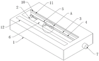
图1为平板以及设置在平板内的各种组件的结构示意图;Fig. 1 is a structural schematic diagram of a flat panel and various components arranged in the flat panel;
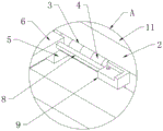
图2为图1的A处结构放大示意图;Figure 2 is an enlarged schematic view of the structure at A in Figure 1;
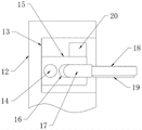
图3为升降板的竖剖结构示意图。Fig. 3 is a schematic diagram of the vertical section structure of the lifting plate.
图中:1平板、2收纳槽、3转动槽、4螺纹杆、5螺母、6连接板、7驱动电机、8延伸杆、9放置块、10活动槽、11盖板、12升降板、13移动槽、14往复丝杠、15丝杠套、16转动通道、17转盘、18横杆、19清洁布、20转动电机。In the figure: 1 flat plate, 2 receiving slot, 3 rotating slot, 4 threaded rod, 5 nut, 6 connecting plate, 7 driving motor, 8 extending rod, 9 placing block, 10 movable slot, 11 cover plate, 12 lifting plate, 13 Moving groove, 14 reciprocating leading screws, 15 leading screw sleeves, 16 rotating channels, 17 rotating disks, 18 cross bars, 19 cleaning cloths, 20 rotating motors.
具体实施方式Detailed ways
下面将结合本实用新型实施例中的附图,对本实用新型实施例中的技术方案进行清楚、完整地描述,显然,所描述的实施例仅仅是本实用新型一部分实施例,而不是全部的实施例。The technical solutions in the embodiments of the present invention will be clearly and completely described below in conjunction with the accompanying drawings in the embodiments of the present invention. Obviously, the described embodiments are only part of the embodiments of the present invention, not all of them. example.
参照图1-3,一种导电粒子检测装置,包括平板1,平板1上端面设有收纳槽2,收纳槽2内侧壁设有转动槽3,转动槽3内转动设有螺纹杆4,转动槽3内设有连接板6,连接板6通过连接机构与螺纹杆4连接,连接机构包括螺纹套设在螺纹杆4外壁的螺母5,螺母5外壁通过连接块设有第二电动伸缩杆,连接板6与电动伸缩杆伸缩端末端固定连接,螺母5、转动槽3、移动槽13与丝杠套15侧剖图均为矩形,且螺母5外壁与转动槽3内壁贴合,丝杠套15外壁与移动槽13内壁贴合,能实现限位,从而人避免螺母5跟随螺纹杆4一起转动,避免丝杠套15跟随往复丝杠14一起转动。Referring to Figures 1-3, a conductive particle detection device includes a
连接板6两侧外壁均通过多根延伸杆8设有放置块9,平板1上端面设有升降槽,升降槽内设有升降板12,升降板12靠近收纳槽2一侧的侧壁设有移动槽13,移动槽13内转动设有往复丝杠14,往复丝杠14外壁螺纹套设有丝杠套15,丝杠套15侧壁设有转动通道16,转动通道16内设有转盘17,丝杠套15上设有与转盘17连接的动力机构,动力机构包括设置在丝杠套15上端面的转动电机20,转动电机20输出轴末端转动贯穿丝杠套15外壁并与转盘17外壁固定连接,转动电机20可以带动转盘17在转动通道16内转动,转盘17底壁与转动通道16内底壁转动连接。The outer walls on both sides of the connecting
转盘17侧壁固定设有横杆18,横杆18底壁设有清洁布19,清洁布19与横杆18底壁之间通过魔术贴连接,清洁布19为超细合成纤维材质,清洁布19借助横杆18实现与丝杠套15的同步往复移动,从而人实现对柔性屏表面的清扫加工处理,其中清洁布19为超细合成纤维材质,能减少对柔性屏表面造成的伤害。
放置块9上端面设有放置槽,放置槽内壁与连接板6上端面均设有橡胶垫,放置槽为柔性屏配合使用,柔性屏四个角处于四块放置块9上端面的放置槽中,橡胶垫起到保护作用。The upper end surface of the
升降槽内底壁设有第二电动伸缩杆,第二电动伸缩杆伸缩端末端与升降板12底壁固定连接,第二电动伸缩杆能实现升降板12的上升展开与下降收纳操作。The inner bottom wall of the lifting groove is provided with a second electric telescopic rod, and the end of the telescopic end of the second electric telescopic rod is fixedly connected with the bottom wall of the
本实用新型使用时,第一电动伸缩杆能带动连接板6与放置块9等组件升降,从而便于下降处于收纳槽2内实现收纳,收纳的时候可以移动盖板11实现收纳槽2的闭合,在不使用的时候避免外部灰尘进入收纳槽2中,上升脱离收纳槽2从而展开便于放置柔性屏移动进入检测箱内进行检测(需要说明的是,本方案进队平板1设备进行了改进,其他设备参考公开(公告)号CN213544705U并未作出改变),在连接板6与放置块9等组件上升脱离收纳槽2且上放置有柔性屏的时候可以启动第二电动伸缩杆,第二电动伸缩杆带动升降板12上升,随后启动转动电机20,转动电机20带动转盘17转动,转盘17带动横杆18转动90°,使其与升降板12之间呈垂直状态,此时再启动第一电动伸缩杆使其带动柔性屏稍微上升一点距离,从而使清洁布19与柔性屏表面接触,此时借助动力装置带动往复丝杠14转动(动力装置可以设置在升降板12内,在图中并未示意),往复丝杠14转动的时候其外壁套设的丝杠套15能借助横杆18带动清洁布19移动实现对柔性屏表面的来回清扫处理,将灰尘清扫掉保证整洁度。When the utility model is used, the first electric telescopic rod can drive the components such as the connecting
以上所述,仅为本实用新型较佳的具体实施方式,但本实用新型的保护范围并不局限于此,任何熟悉本技术领域的技术人员在本实用新型揭露的技术范围内,根据本实用新型的技术方案及其实用新型构思加以等同替换或改变,都应涵盖在本实用新型的保护范围之内。The above is only a preferred embodiment of the utility model, but the scope of protection of the utility model is not limited thereto. The equivalent replacement or change of the new technical solution and the concept of the utility model shall be covered by the protection scope of the utility model.
Claims (6)
Priority Applications (1)
| Application Number | Priority Date | Filing Date | Title |
|---|---|---|---|
| CN202222453518.3U CN218496690U (en) | 2022-09-15 | 2022-09-15 | Conductive particle detection device |
Applications Claiming Priority (1)
| Application Number | Priority Date | Filing Date | Title |
|---|---|---|---|
| CN202222453518.3U CN218496690U (en) | 2022-09-15 | 2022-09-15 | Conductive particle detection device |
Publications (1)
| Publication Number | Publication Date |
|---|---|
| CN218496690U true CN218496690U (en) | 2023-02-17 |
Family
ID=85189627
Family Applications (1)
| Application Number | Title | Priority Date | Filing Date |
|---|---|---|---|
| CN202222453518.3U Expired - Fee Related CN218496690U (en) | 2022-09-15 | 2022-09-15 | Conductive particle detection device |
Country Status (1)
| Country | Link |
|---|---|
| CN (1) | CN218496690U (en) |
-
2022
- 2022-09-15 CN CN202222453518.3U patent/CN218496690U/en not_active Expired - Fee Related
Similar Documents
| Publication | Publication Date | Title |
|---|---|---|
| WO2021189172A1 (en) | Dust removal and cleaning device for testing planar flexible materials | |
| CN108214304B (en) | A grinding device with a vertically movable grinding block | |
| CN112158385A (en) | Large-scale display blocking pad pasting device | |
| CN209902135U (en) | A cutting device for electronic wire processing | |
| CN211839152U (en) | A dust removal cleaning device for test of flexible material in plane | |
| CN212148148U (en) | Easy-to-clean nano blackboard | |
| CN214305971U (en) | Digital media art design show propaganda device | |
| CN212168234U (en) | Computer hardware ash removal device | |
| CN220084885U (en) | A power supply automatic plug-in test equipment | |
| CN218360862U (en) | Cleaning device for machining mechanical bearing | |
| CN207343397U (en) | Non-contact cleaning equipment | |
| CN110834263A (en) | Polishing machine for processing LED touch screen | |
| CN218312606U (en) | Surface grinding device for processing mechanical parts | |
| CN111035335A (en) | A cleaning robot that is easy to clean dead corners | |
| CN222232361U (en) | Micro-crack detection device | |
| CN222537916U (en) | Cork plug waxing attachment convenient to it is clean | |
| CN218691885U (en) | Intelligent conference tablet with protection function | |
| CN219053881U (en) | A grinding structure for the production of wooden furniture | |
| CN218548289U (en) | Electric automatization is with having console that prevents mistake and bump function | |
| CN222089853U (en) | Circuit board surface treatment equipment | |
| CN217508016U (en) | Lighting distribution box convenient to clearance | |
| CN221419746U (en) | A plate loading machine for mechanical processing | |
| CN219116119U (en) | A printing plate storage machine | |
| CN217018047U (en) | Automatic press-fit device for stainless steel barrel | |
| CN217664850U (en) | A board surface cleaning device for PCB circuit board production and processing |
Legal Events
| Date | Code | Title | Description |
|---|---|---|---|
| GR01 | Patent grant | ||
| GR01 | Patent grant | ||
| CF01 | Termination of patent right due to non-payment of annual fee |
Granted publication date: 20230217 |
|
| CF01 | Termination of patent right due to non-payment of annual fee |