CN218482368U - Parallel storage battery capable of being replaced in single group - Google Patents
Parallel storage battery capable of being replaced in single group Download PDFInfo
- Publication number
- CN218482368U CN218482368U CN202222013634.3U CN202222013634U CN218482368U CN 218482368 U CN218482368 U CN 218482368U CN 202222013634 U CN202222013634 U CN 202222013634U CN 218482368 U CN218482368 U CN 218482368U
- Authority
- CN
- China
- Prior art keywords
- battery
- groove
- outer frame
- replaced
- parallel
- Prior art date
- Legal status (The legal status is an assumption and is not a legal conclusion. Google has not performed a legal analysis and makes no representation as to the accuracy of the status listed.)
- Expired - Fee Related
Links
Images




Classifications
-
- Y—GENERAL TAGGING OF NEW TECHNOLOGICAL DEVELOPMENTS; GENERAL TAGGING OF CROSS-SECTIONAL TECHNOLOGIES SPANNING OVER SEVERAL SECTIONS OF THE IPC; TECHNICAL SUBJECTS COVERED BY FORMER USPC CROSS-REFERENCE ART COLLECTIONS [XRACs] AND DIGESTS
- Y02—TECHNOLOGIES OR APPLICATIONS FOR MITIGATION OR ADAPTATION AGAINST CLIMATE CHANGE
- Y02E—REDUCTION OF GREENHOUSE GAS [GHG] EMISSIONS, RELATED TO ENERGY GENERATION, TRANSMISSION OR DISTRIBUTION
- Y02E60/00—Enabling technologies; Technologies with a potential or indirect contribution to GHG emissions mitigation
- Y02E60/10—Energy storage using batteries
Landscapes
- Battery Mounting, Suspending (AREA)
Abstract
本实用新型涉及蓄电池技术领域,具体公开了一种可单组更换的并联型蓄电池,包括:外框,外框的一侧面开设有多个呈等间距分布的安装槽,安装槽的内腔水平插接有蓄电池单组;两个导电板分别内嵌在外框的两侧,多个弹性导电片分别与两个导电板固定连接;定位块的下端与定位槽的内腔插接;有益效果为:通过在外框的侧面开设有多个呈等间距分布的安装槽,所述安装槽的上端内壁设置为三阶的阶梯型,蓄电池单组上端面的两端均设置有极柱,因此本装置的蓄电池单组能够从外框的侧面进行抽拉拆卸,并且单个蓄电池单组拆卸更换时其他的蓄电池单组依旧保持电性连接,从而避免了影响整个蓄电池的使用。

The utility model relates to the technical field of storage batteries, and specifically discloses a parallel-connected storage battery that can be replaced by a single group, comprising: an outer frame, one side of the outer frame is provided with a plurality of installation grooves distributed at equal intervals, and the inner cavity of the installation groove is horizontal A battery pack is plugged in; two conductive plates are respectively embedded on both sides of the outer frame, and a plurality of elastic conductive plates are respectively fixedly connected to the two conductive plates; the lower end of the positioning block is plugged into the inner cavity of the positioning groove; the beneficial effect is : By opening a plurality of installation grooves distributed at equal intervals on the side of the outer frame, the inner wall of the upper end of the installation groove is set as a three-step ladder type, and both ends of the upper end surface of the battery single group are provided with poles, so this device The single battery pack can be pulled and disassembled from the side of the outer frame, and when a single battery pack is removed and replaced, other battery packs still remain electrically connected, thereby avoiding affecting the use of the entire battery.
Description
技术领域technical field
本实用新型涉及蓄电池技术领域,具体为一种可单组更换的并联型蓄电池。The utility model relates to the technical field of accumulators, in particular to a parallel-connected accumulator which can be replaced by a single group.
背景技术Background technique
蓄电池是把化学能转换成电能的装置。放电后,能够用充电的方式使内部活性物质再生——把电能储存为化学能;需要放电时再次把化学能转换为电能。A battery is a device that converts chemical energy into electrical energy. After discharge, the internal active material can be regenerated by charging—the electrical energy is stored as chemical energy; when discharge is required, the chemical energy is converted into electrical energy again.
目前,并联型蓄电池通过导电片将多个蓄电池单组的极柱相连接,并且正极与正极连接,负极与负极连接,以增大整个蓄电池的能量储备、分散蓄电池单组的供电压力,从而延长电池的使用寿命。At present, parallel-connected batteries connect the poles of multiple battery groups through conductive sheets, and the positive poles are connected to the positive poles, and the negative poles are connected to the negative poles, so as to increase the energy reserve of the entire battery and disperse the power supply pressure of the single battery group. battery life.
但现有的并联型蓄电池,其蓄电池单组一般由上而下安装在外框内部,由外框上端盖内嵌的导电片将多个蓄电池单组的极柱相连,但蓄电池单组在拆卸更换时,需要将外框的上端盖拆下,从而导致整个蓄电池无法继续使用。However, in the existing parallel-connected batteries, the single battery groups are generally installed inside the outer frame from top to bottom, and the poles of multiple battery single groups are connected by the conductive sheet embedded in the upper end cover of the outer frame. , the upper end cover of the outer frame needs to be removed, resulting in the failure of the entire battery to continue to be used.
如公开号为CN108461698A的中国发明公开了一种串并联组合式蓄电池组;其通过并联网实现电池单体之间的并联。For example, the Chinese invention whose publication number is CN108461698A discloses a series-parallel combined battery pack; it realizes the parallel connection between battery cells through parallel networking.
该蓄电池组的并联网为一体式结构,当蓄电池单组需要单独拆卸时,需要首先对并联网进行拆卸,此时多个蓄电池单组的并联被断开,整个蓄电池组无法继续使用。The parallel network of the battery pack is an integrated structure. When a single battery pack needs to be disassembled separately, the parallel network needs to be disassembled first. At this time, the parallel connection of multiple single battery packs is disconnected, and the entire battery pack cannot continue to be used.
实用新型内容Utility model content
本实用新型的目的在于提供一种可单组更换的并联型蓄电池,以解决上述背景技术中提出的蓄电池单组在拆卸更换时整个蓄电池无法继续使用的问题。The purpose of the utility model is to provide a parallel-connected storage battery that can be replaced by a single set, so as to solve the problem that the entire storage battery cannot continue to be used when a single battery set is disassembled and replaced in the above-mentioned background technology.
为实现上述目的,本实用新型提供如下技术方案:一种可单组更换的并联型蓄电池,包括:In order to achieve the above purpose, the utility model provides the following technical solution: a parallel battery that can be replaced by a single set, including:
外框,所述外框的一侧面开设有多个呈等间距分布的安装槽,所述安装槽的内腔水平插接有蓄电池单组,所述安装槽的上端内壁和蓄电池单组的上端面均设置为三阶的阶梯型,所述蓄电池单组的上端面中部开设有定位槽,所述蓄电池单组上端面的两端均固定连接有极柱,所述极柱的上表面贴合有弹性导电片;The outer frame, one side of the outer frame is provided with a plurality of installation slots distributed at equal intervals, the inner cavity of the installation slot is horizontally inserted with a single battery group, the upper inner wall of the installation slot and the upper part of the single battery group The end faces are all set in a three-step ladder type, and the middle part of the upper end face of the battery single group is provided with a positioning groove. Elastic conductive sheet;
导电板,所述导电板设置有两个,两个所述导电板分别内嵌在外框的两侧,多个所述弹性导电片分别与两个导电板固定连接,两个所述导电板的端部均固定连接有接线柱,所述接线柱的上端延伸至外框的上方;及There are two conductive plates, the two conductive plates are respectively embedded on both sides of the outer frame, and a plurality of the elastic conductive plates are respectively fixedly connected to the two conductive plates, and the two conductive plates Both ends are fixedly connected with binding posts, and the upper ends of the binding posts extend to the top of the outer frame; and
定位块,所述定位块活动插接于安装槽的上端内壁中部,所述定位块的下端与定位槽的内腔插接。A positioning block, the positioning block is movably inserted in the middle part of the inner wall of the upper end of the installation groove, and the lower end of the positioning block is inserted into the inner cavity of the positioning groove.
优选的,所述蓄电池单组的一端面固定连接有密封板,所述密封板覆盖在安装槽的开口端,所述密封板的表面粘接有密封垫。Preferably, a sealing plate is fixedly connected to one end of the single battery pack, the sealing plate covers the opening end of the installation groove, and a sealing gasket is bonded to the surface of the sealing plate.
优选的,所述外框的上端内部开设有多个呈等间距分布的导向槽,多个所述导向槽分别位于多个蓄电池单组的中部正上方。Preferably, a plurality of guide grooves distributed at equal intervals are opened inside the upper end of the outer frame, and the plurality of guide grooves are respectively located directly above the middle parts of the plurality of battery packs.
优选的,所述导向槽的内腔滑动安装有限位板,多个所述限位板分别与多个定位块的上端固定连接。Preferably, a limiting plate is slidably installed in the inner cavity of the guide groove, and a plurality of the limiting plates are respectively fixedly connected with upper ends of a plurality of positioning blocks.
优选的,所述限位板的上表面贴合有压板,所述压板的上表面固定连接有螺柱,所述螺柱通过螺纹活动贯穿导向槽的上端内壁,所述螺柱的上端固定连接有旋钮。Preferably, the upper surface of the limiting plate is attached with a pressure plate, and the upper surface of the pressure plate is fixedly connected with a stud, and the stud moves through the inner wall of the upper end of the guide groove through threads, and the upper end of the stud is fixedly connected There are knobs.
优选的,所述导向槽内腔的两侧均设置有推力弹簧,所述推力弹簧的上下两端分别贴合限位板的下表面和导向槽的下端内壁。Preferably, both sides of the inner cavity of the guide groove are provided with thrust springs, and the upper and lower ends of the thrust spring are respectively attached to the lower surface of the limiting plate and the inner wall of the lower end of the guide groove.
优选的,所述密封板的正面开设有“匚”字形的凹槽,所述凹槽内转动安装有折叠把手。Preferably, a "匚"-shaped groove is opened on the front of the sealing plate, and a folding handle is rotatably installed in the groove.
与现有技术相比,本实用新型的有益效果是:Compared with the prior art, the beneficial effects of the utility model are:
本实用新型通过在外框的侧面开设有多个呈等间距分布的安装槽,所述安装槽的上端内壁设置为三阶的阶梯型,安装槽上端内壁的两端均安装有弹性导电片,蓄电池单组插接于安装槽的内腔并与之相适配,蓄电池单组上端面的两端均设置有极柱,弹性导电片与极柱挤压接触,因此本装置的蓄电池单组能够从外框的侧面进行抽拉拆卸,并且单个蓄电池单组拆卸更换时其他的蓄电池单组依旧保持电性连接,从而避免了影响整个蓄电池的使用。In the utility model, a plurality of installation grooves distributed at equal intervals are provided on the side of the outer frame. The inner wall of the upper end of the installation groove is set as a three-step ladder type, and the two ends of the inner wall of the upper end of the installation groove are installed with elastic conductive sheets. The single group is plugged into the inner cavity of the installation groove and adapted to it. Both ends of the upper end surface of the single battery group are provided with poles, and the elastic conductive sheet is pressed into contact with the poles. Therefore, the single battery group of this device can be used from The side of the outer frame is pulled and disassembled, and when a single battery pack is disassembled and replaced, other battery packs are still electrically connected, thereby avoiding affecting the use of the entire battery pack.
附图说明Description of drawings
图1为本实用新型整体结构立体示意图;Fig. 1 is a three-dimensional schematic diagram of the overall structure of the utility model;
图2为本实用新型外框结构内部示意图;Fig. 2 is the internal schematic diagram of the outer frame structure of the utility model;
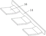
图3为本实用新型弹性导电片结构立体示意图;Fig. 3 is a three-dimensional schematic diagram of the structure of the elastic conductive sheet of the present invention;
图4为本实用新型蓄电池单组结构立体示意图;Fig. 4 is a three-dimensional schematic diagram of the single-group structure of the storage battery of the utility model;
图5为本实用新型图安装槽中A-A处结构侧剖示意图。Fig. 5 is a schematic side sectional view of the structure at A-A in the installation groove of the utility model.
图中:1、外框;2、安装槽;3、蓄电池单组;4、定位槽;5、密封板;6、密封垫;7、定位块;8、旋钮;9、导向槽;10、限位板;11、压板;12、螺柱; 13、推力弹簧;14、导电板;15、接线柱;16、弹性导电片;17、极柱;18、折叠把手。In the figure: 1. Outer frame; 2. Installation groove; 3. Battery single group; 4. Positioning groove; 5. Sealing plate; 6. Gasket; 7. Positioning block; 8. Knob; 9. Guide groove; 10. Limiting plate; 11, pressure plate; 12, stud; 13, thrust spring; 14, conductive plate; 15, terminal post; 16, elastic conductive sheet; 17, pole; 18, folding handle.
具体实施方式Detailed ways
为了使本发明的目的、技术方案进行清楚、完整地描述,及优点更加清楚明白,以下结合附图对本发明实施例进行进一步详细说明。应当理解,此处所描述的具体实施例是本发明一部分实施例,而不是全部的实施例,仅仅用以解释本发明实施例,并不用于限定本发明实施例,本领域普通技术人员在没有做出创造性劳动前提下所获得的所有其他实施例,都属于本发明保护的范围。In order to clearly and completely describe the purpose, technical solution, and advantages of the present invention, the embodiments of the present invention will be further described in detail below in conjunction with the accompanying drawings. It should be understood that the specific embodiments described here are part of the embodiments of the present invention, rather than all embodiments, and are only used to explain the embodiments of the present invention, and are not intended to limit the embodiments of the present invention. All other embodiments obtained under the premise of creative work all belong to the protection scope of the present invention.
请参阅图1-图5,本实用新型提供一种技术方案:Please refer to Fig. 1-Fig. 5, the utility model provides a kind of technical scheme:
实施例一Embodiment one
一种可单组更换的并联型蓄电池,包括:外框1、导电板14和定位块7。A parallel-connected storage battery that can be replaced by a single set includes: an
具体的,在外框1的一侧面开设有多个呈等间距分布的安装槽2,安装槽2 的内腔水平插接有蓄电池单组3,安装槽2的上端内壁和蓄电池单组3的上端面均设置为三阶的阶梯型,如图2所示,将蓄电池单组3水平插入安装槽2的内腔后,安装槽2上端内壁中部的台阶与蓄电池单组3上端面中部的台阶相互贴合,而其余的台阶之间留有一定的间隙,蓄电池单组3的上端面中部开设有定位槽4,蓄电池单组3上端面的两端均固定连接有极柱17,极柱17的上表面贴合有弹性导电片16,安装槽2上端内壁与蓄电池单组3上端面的台阶之间间隙的作用用于放置弹性导电片16和极柱17,弹性导电片16由弹性金属片弯折制成,弹性导电片16受到极柱17挤压后能够发生弹性形变,并与极柱17之间始终保持接触状态;Specifically, on one side of the
其次,导电板14设置有两个,两个导电板14分别内嵌在外框1的两侧,多个弹性导电片16分别与两个导电板14固定连接,两个导电板14的端部均固定连接有接线柱15,接线柱15的上端延伸至外框1的上方,两个接线柱15分别用作整个蓄电池的正负极,两个导电板14分别将多个蓄电池单组3的正极以及多个蓄电池单组3的负极电性连接在一起,从而实现多个蓄电池单组3的并联;Secondly, there are two
进一步的,定位块7活动插接于安装槽2的上端内壁中部,定位块7的下端与定位槽4的内腔插接,定位块7插入定位槽4的内腔用于对蓄电池单组3 进行定位,以避免蓄电池单组3从安装槽2的内腔发生脱离。Further, the
实施例二Embodiment two
在实施例一的基础上,为了避免安装槽2的内腔进灰进水,本申请还具有在蓄电池单组3的一端面固定连接有密封板5,密封板5覆盖在安装槽2的开口端,密封板5的表面粘接有密封垫6,密封板5的设置用于对蓄电池单组3进行防护,密封板5配合密封垫6能够对安装槽2的开口端进行密封,以避免安装槽2的内腔进灰进水。On the basis of
实施例三Embodiment three
在实施例二的基础上,为了避免定位块7掉落,本申请还具有在外框1的上端内部开设有多个呈等间距分布的导向槽9,多个导向槽9分别位于多个蓄电池单组3的中部正上方,导向槽9的内腔滑动安装有限位板10,多个限位板10 分别与多个定位块7的上端固定连接,限位板10能够在导向槽9的内腔竖直上下滑动,但限位板10不会与导向槽9的内腔发生分离,因此定位块7能够上下移动,但定位块7不会掉落,且定位块7向上移动时能够收进导向槽9的内腔,以确保与定位槽4分离。On the basis of
实施例四Embodiment four
在实施例三的基础上,为了推动定位块7向下移动,本申请还具有在限位板10的上表面贴合有压板11,压板11的上表面固定连接有螺柱12,螺柱12 通过螺纹活动贯穿导向槽9的上端内壁,螺柱12的上端固定连接有旋钮8,拧动旋钮8时,螺柱12通过螺纹能够带动压板11向下移动,压板11挤压限位板 10挤压带动定位块7和限位板10向下移动,从而确保定位块7插入定位槽4的内腔来对蓄电池单组3进行定位。On the basis of
实施例五Embodiment five
在实施例四的基础上,为了确保定位块7能够自动收进导向槽9的内腔,本申请还具有在导向槽9内腔的两侧均设置有推力弹簧13,推力弹簧13的上下两端分别贴合限位板10的下表面和导向槽9的下端内壁,推力弹簧13提供推力,当螺柱12逆向拧动带动压板11上移时,限位板10在推力弹簧13的推力作用下能够自动上移并将定位块7收进导向槽9的内腔。On the basis of
实施例六Embodiment six
在实施例五的基础上,为了便于对蓄电池单组3进行抽拉,本申请还具有在密封板5的正面开设有“匚”字形的凹槽,凹槽内转动安装有折叠把手18,折叠把手18的设置便于对蓄电池单组3进行抽拉,折叠把手18为现有技术中已经成熟的结构,此处不做赘述。On the basis of
本方案具体为:拧动旋钮8带动螺柱12转动,螺柱12通过螺纹带动压板 11上移,此时限位板10在推力弹簧13的推力作用下上移,并带动定位块7上移收进导向槽9的内腔,定位块7与定位槽4的内腔分离后,通过拉动折叠把手18即可将蓄电池单组3从安装槽2的内腔抽出,并且其他的蓄电池单组3依旧保持并联,不会影响整个蓄电池的正常使用;This scheme is specifically: turn the
然后将新的蓄电池单组3水平插入安装槽2的内腔,直至极柱17与弹性导电片16对应,新的蓄电池单组3便并联进整个蓄电池内,然后拧动该蓄电池单组3上方的旋钮8,此时压板11下移带动限位板10和定位块7下移,直至定位块7的下端插入定位槽4的内腔,即可实现对该蓄电池单组3的定位,以避免蓄电池单组3从安装槽2的内腔发生移动甚至脱离。Then insert the new battery
尽管已经示出和描述了本实用新型的实施例,对于本领域的普通技术人员而言,可以理解在不脱离本实用新型的原理和精神的情况下可以对这些实施例进行多种变化、修改、替换和变型,本实用新型的范围由所附权利要求及其等同物限定。Although the embodiments of the present invention have been shown and described, those skilled in the art can understand that various changes and modifications can be made to these embodiments without departing from the principle and spirit of the present invention , replacements and modifications, the scope of the present utility model is defined by the appended claims and their equivalents.
Claims (7)
Priority Applications (1)
| Application Number | Priority Date | Filing Date | Title |
|---|---|---|---|
| CN202222013634.3U CN218482368U (en) | 2022-08-01 | 2022-08-01 | Parallel storage battery capable of being replaced in single group |
Applications Claiming Priority (1)
| Application Number | Priority Date | Filing Date | Title |
|---|---|---|---|
| CN202222013634.3U CN218482368U (en) | 2022-08-01 | 2022-08-01 | Parallel storage battery capable of being replaced in single group |
Publications (1)
| Publication Number | Publication Date |
|---|---|
| CN218482368U true CN218482368U (en) | 2023-02-14 |
Family
ID=85166191
Family Applications (1)
| Application Number | Title | Priority Date | Filing Date |
|---|---|---|---|
| CN202222013634.3U Expired - Fee Related CN218482368U (en) | 2022-08-01 | 2022-08-01 | Parallel storage battery capable of being replaced in single group |
Country Status (1)
| Country | Link |
|---|---|
| CN (1) | CN218482368U (en) |
-
2022
- 2022-08-01 CN CN202222013634.3U patent/CN218482368U/en not_active Expired - Fee Related
Similar Documents
| Publication | Publication Date | Title |
|---|---|---|
| CN102347512B (en) | Large-capacity lithium ion battery | |
| CN210607513U (en) | Valve-controlled sealed lead-acid storage battery for power cycle | |
| CN110311164B (en) | Detachable mixed-form lithium ion battery parallel-connection pressurizing and capacity-increasing battery pack structure | |
| CN217903198U (en) | High-rate lithium ion battery cell and tab pressing device | |
| CN201877492U (en) | Novel valve-regulated lead-acid storage battery for double 12 V starting | |
| CN118712510A (en) | A lithium iron phosphate battery positive electrode and a lithium ion battery pack | |
| CN208781994U (en) | A kind of battery having heat sinking function | |
| CN218274829U (en) | Ternary lithium battery with replaceable battery core | |
| CN207303269U (en) | A kind of carbon alloy battery for preventing electric leakage | |
| CN206210955U (en) | A kind of practical Li ion cells unit | |
| CN209766510U (en) | A battery pack based on internally mounted stability | |
| CN211150711U (en) | Portable direct-connected internalized valve-regulated sealed lead-acid battery | |
| CN210467953U (en) | Novel high-performance green battery pack | |
| CN208873838U (en) | A kind of packaging equipment for lithium ion battery production | |
| CN222380630U (en) | Solar colloid battery | |
| CN223378234U (en) | Recovery power storage device of button cell | |
| CN218385639U (en) | Integrated integrated structure of standard module FPC | |
| CN103606721A (en) | Cooling and thermal insulation battery device | |
| CN205508955U (en) | Polymer lithium ion battery structure of discharging | |
| CN222394963U (en) | Insulation structure of a sodium ion battery box | |
| CN216450740U (en) | A cylindrical polymer battery | |
| CN214176162U (en) | Lithium battery module connecting device | |
| CN222690725U (en) | Ion battery structure for supplementing active substances | |
| CN223858159U (en) | Single-cell batteries and electrical equipment | |
| CN221041463U (en) | Stacked combined cylindrical lithium ion battery pack |
Legal Events
| Date | Code | Title | Description |
|---|---|---|---|
| GR01 | Patent grant | ||
| GR01 | Patent grant | ||
| CF01 | Termination of patent right due to non-payment of annual fee | ||
| CF01 | Termination of patent right due to non-payment of annual fee |
Granted publication date: 20230214 |