CN218481731U - TFT polaroid position detection equipment - Google Patents
TFT polaroid position detection equipment Download PDFInfo
- Publication number
- CN218481731U CN218481731U CN202222951313.8U CN202222951313U CN218481731U CN 218481731 U CN218481731 U CN 218481731U CN 202222951313 U CN202222951313 U CN 202222951313U CN 218481731 U CN218481731 U CN 218481731U
- Authority
- CN
- China
- Prior art keywords
- detection
- plate
- tft
- moving mechanism
- movement assembly
- Prior art date
- Legal status (The legal status is an assumption and is not a legal conclusion. Google has not performed a legal analysis and makes no representation as to the accuracy of the status listed.)
- Expired - Fee Related
Links
Images


Landscapes
- Length Measuring Devices By Optical Means (AREA)
Abstract
本实用新型涉及一种TFT偏光片位置检测设备,包括第一检测机构、第二检测机构、第一移动机构、第二移动机构、底板以及通过支撑柱固定在所述底板上的显示器,所述第一检测机构通过第一固定板安装在所述第一移动机构上,所述第二检测机构通过第二固定板安装在所述第二移动机构上,所述第一移动机构和所述第二移动机构分别通过桥梁安装在所述底板上,且所述底板上设有用于放置产品的检测位,所述第一检测机构与所述第二检测机构均位于所述检测位的上方。本实用新型通过合理的设计,能够快速检测偏光片位置与产品边缘、显示图案位置是否在标准范围内,代替人工检测,大大提高了检测效率和检测精度,能够满足客户的需求。

The utility model relates to a TFT polarizer position detection device, comprising a first detection mechanism, a second detection mechanism, a first moving mechanism, a second moving mechanism, a base plate and a display fixed on the base plate through a support column, the The first detection mechanism is installed on the first moving mechanism through the first fixing plate, the second detection mechanism is installed on the second moving mechanism through the second fixing plate, the first moving mechanism and the first moving mechanism The two moving mechanisms are respectively installed on the bottom plate through bridges, and the bottom plate is provided with a detection position for placing products, and both the first detection mechanism and the second detection mechanism are located above the detection position. Through reasonable design, the utility model can quickly detect whether the position of the polarizer, the edge of the product, and the position of the display pattern are within the standard range, replaces manual detection, greatly improves the detection efficiency and detection accuracy, and can meet the needs of customers.
Description
技术领域technical field
本实用新型涉及偏光片技术领域,特别是涉及一种TFT偏光片位置检测设备。The utility model relates to the technical field of polarizers, in particular to a TFT polarizer position detection device.
背景技术Background technique
偏光片的全称是偏振光片,液晶显示器的成像必须依靠偏光片,所有的液晶都有前后两片偏振光片紧贴在液晶玻璃,组成总厚度1mm左右的液晶片。而在液晶显示器的生产过程中,需要对其显示面板的偏光片贴合情况进行精度检测,目前,对偏光片贴合是否符合要求的判断,通常由人工完成,这种人工处理方式,检测精度和检测效率都比较低,且肉眼在长时间工作后,容易产生视觉疲累,导致漏检、错检。The full name of polarizer is polarizer. The imaging of liquid crystal display must rely on polarizer. All liquid crystals have two front and rear polarizers attached to the liquid crystal glass to form a liquid crystal sheet with a total thickness of about 1mm. In the production process of liquid crystal displays, it is necessary to carry out precision testing on the bonding of the polarizer of the display panel. At present, the judgment of whether the polarizing film meets the requirements is usually done manually. This manual processing method has a high detection accuracy. And the detection efficiency is relatively low, and the naked eye is prone to visual fatigue after working for a long time, resulting in missed detection and wrong detection.
实用新型内容Utility model content
基于此,有必要针对现有技术中存在的问题,提供一种TFT偏光片位置检测设备。Based on this, it is necessary to provide a TFT polarizer position detection device for the problems existing in the prior art.
一种TFT偏光片位置检测设备,包括第一检测机构、第二检测机构、第一移动机构、第二移动机构、底板以及通过支撑柱固定在所述底板上的显示器,所述第一检测机构通过第一固定板安装在所述第一移动机构上,所述第二检测机构通过第二固定板安装在所述第二移动机构上,所述第一移动机构和所述第二移动机构分别通过桥梁安装在所述底板上,且所述底板上设有用于放置产品的检测位,所述第一检测机构与所述第二检测机构均位于所述检测位的上方。A TFT polarizer position detection device, comprising a first detection mechanism, a second detection mechanism, a first movement mechanism, a second movement mechanism, a bottom plate and a display fixed on the bottom plate by a support column, the first detection mechanism The first moving mechanism is installed on the first moving mechanism through the first fixing plate, the second detection mechanism is installed on the second moving mechanism through the second fixing plate, and the first moving mechanism and the second moving mechanism are respectively It is installed on the bottom plate through a bridge, and the bottom plate is provided with a detection position for placing products, and both the first detection mechanism and the second detection mechanism are located above the detection position.
在其中一个实施例中,所述第一检测机构包括第一CCD相机,所述第二检测机构包括第二CCD相机,所述第一CCD相机和所述第二CCD相机均用于检测TFT与偏光片的贴合度。In one of the embodiments, the first detection mechanism includes a first CCD camera, and the second detection mechanism includes a second CCD camera, and both the first CCD camera and the second CCD camera are used to detect TFT and The degree of fit of the polarizer.
在其中一个实施例中,所述检测位上设有第一背光灯和第二背光灯,所述第一背光灯通过托板安装在所述底板上,且位于所述第一CCD相机的下方;所述第二背光灯安装在所述底板上,且位于所述第二CCD相机的下方。In one of the embodiments, the detection position is provided with a first backlight and a second backlight, and the first backlight is installed on the bottom plate through a supporting plate, and is located below the first CCD camera ; The second backlight is installed on the bottom plate and located below the second CCD camera.
在其中一个实施例中,所述底板上设有若干限位槽以及用于安装所述第二背光灯的安装槽。In one of the embodiments, the bottom plate is provided with several limiting slots and installation slots for installing the second backlight.
在其中一个实施例中,所述检测位上还设有第一档条、第二档条和若干定位块,所述定位块安装在所述限位槽内,所述第一档条和所述第二档条分别安装在所述底板上,且平行分布。In one of the embodiments, the detection position is further provided with a first gear bar, a second gear bar and several positioning blocks, the positioning blocks are installed in the limit slot, and the first gear bar and the The second gear bars are respectively installed on the bottom plate and distributed in parallel.
在其中一个实施例中,所述第一移动机构包括第一横向移动组件和第一垂直移动组件,所述第一垂直移动组件通过连接块安装在所述第一横向移动组件的上方,所述第一横向移动组件通过连接块安装在所述桥梁上;所述第二移动机构包括第二垂直移动组件,所述第二垂直移动组件通过连接块安装在所述桥梁上,且位于所述第一移动机构的一侧。In one of the embodiments, the first moving mechanism includes a first lateral moving assembly and a first vertical moving assembly, and the first vertical moving assembly is installed above the first lateral moving assembly through a connecting block, the The first lateral movement assembly is installed on the bridge through the connection block; the second movement mechanism includes a second vertical movement assembly, the second vertical movement assembly is installed on the bridge through the connection block, and is located at the first One side of the moving mechanism.
在其中一个实施例中,所述第一横向移动组件、所述第一垂直移动组件和所述第二垂直移动组件结构相同,且所述第一垂直移动组件垂直于所述第一横向移动组件,并与所述第二垂直移动组件平行分布;In one of the embodiments, the first lateral movement component, the first vertical movement component and the second vertical movement component have the same structure, and the first vertical movement component is perpendicular to the first lateral movement component , and distributed parallel to the second vertical moving component;
所述第一横向移动组件包括安装板、第一侧板、第二侧板、第一滑轨、第二滑轨、螺杆、滑块和手轮,所述第一侧板和所述第二侧板分别安装在所述安装板的两侧,所述滑块的两端分别设有通孔,中部设有与所述螺杆相适配的螺孔,所述第一滑轨与所述第二滑轨分别穿过所述通孔并固定在所述第一侧板与所述第二侧板之间,所述螺杆的一端依次穿过所述第一侧板、滑块并固定在所述第二侧板上,另一端与所述手轮连接,且所述手轮与所述第一侧板之前设有锁紧件。The first lateral movement assembly includes a mounting plate, a first side plate, a second side plate, a first slide rail, a second slide rail, a screw, a slider and a hand wheel, and the first side plate and the second The side plates are respectively installed on both sides of the mounting plate, through holes are respectively provided at both ends of the slider, and screw holes matching the screw are provided in the middle, and the first slide rail and the second Two sliding rails pass through the through holes respectively and are fixed between the first side plate and the second side plate, and one end of the screw rod passes through the first side plate and the slider in sequence and is fixed on the The other end of the second side plate is connected to the hand wheel, and a locking piece is provided between the hand wheel and the first side plate.
在其中一个实施例中,所述底板的底部设有若干脚垫。In one of the embodiments, the bottom of the bottom plate is provided with several foot pads.
上述一种TFT偏光片位置检测设备,通过合理的设计,能够快速检测偏光片位置与产品边缘、显示图案位置是否在标准范围内,代替人工,提高了检测效率,同时避免在人工检测过程中出现错检、漏检的现象发生,有利于提高检测精度,保证产品的质量,满足客户的需求。The above-mentioned TFT polarizer position detection equipment, through a reasonable design, can quickly detect whether the position of the polarizer, the edge of the product, and the position of the display pattern are within the standard range, replacing manual work, improving the detection efficiency, and avoiding the occurrence of errors in the manual detection process. The occurrence of false detection and missed detection is conducive to improving detection accuracy, ensuring product quality, and meeting customer needs.
附图说明Description of drawings
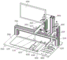
图1为本实用新型一种TFT偏光片位置检测设备的整体结构示意图;Fig. 1 is the overall structure schematic diagram of a kind of TFT polarizer position detection equipment of the present utility model;
图2为本实用新型一种TFT偏光片位置检测设备的底板结构示意图;Fig. 2 is a schematic diagram of the bottom plate structure of a TFT polarizer position detection device of the present invention;
图3为本实用新型一种TFT偏光片位置检测设备的移动组件示意图;3 is a schematic diagram of a moving assembly of a TFT polarizer position detection device of the present invention;
图4为本实用新型一种TFT偏光片位置检测设备的使用状态示意图。FIG. 4 is a schematic view of a TFT polarizer position detection device of the present invention in use.
其中,100、第一检测机构,110、第一CCD相机,120、第一固定板,200、第二检测机构,210、第二CCD相机,220、第二固定板,300、第一移动机构,310、第一横向移动组件,311、安装板,312、第一侧板,313、第二侧板,314、第一滑轨,315、第二滑轨,316、螺杆,317、滑块,318、手轮,319、锁紧件,320、第一垂直移动组件,400、第二移动机构,500、底板,510、限位槽,520、安装槽,530、脚垫,600、检测位,610、第一背光灯,620、第二背光灯,630、托板,640、第一档条,650、第二档条,660、定位块,700、桥梁,800、支撑柱,900、显示器。Among them, 100, the first detection mechanism, 110, the first CCD camera, 120, the first fixed plate, 200, the second detection mechanism, 210, the second CCD camera, 220, the second fixed plate, 300, the first moving mechanism , 310, the first lateral movement assembly, 311, the mounting plate, 312, the first side plate, 313, the second side plate, 314, the first slide rail, 315, the second slide rail, 316, the screw rod, 317, the slider , 318, hand wheel, 319, locking member, 320, the first vertical moving assembly, 400, the second moving mechanism, 500, bottom plate, 510, limit groove, 520, installation groove, 530, foot pad, 600, detection position, 610, first backlight, 620, second backlight, 630, pallet, 640, first rail, 650, second rail, 660, positioning block, 700, bridge, 800, support column, 900 ,monitor.
具体实施方式Detailed ways
为使本实用新型的上述目的、特征和优点能够更加明显易懂,下面结合附图对本实用新型的具体实施方式做详细的说明。在下面的描述中阐述了很多具体细节以便于充分理解本实用新型。但是本实用新型能够以很多不同于在此描述的其它方式来实施,本领域技术人员可以在不违背本实用新型内涵的情况下做类似改进,因此本实用新型不受下面公开的具体实施例的限制。In order to make the above purpose, features and advantages of the present utility model more obvious and understandable, the specific implementation of the present utility model will be described in detail below in conjunction with the accompanying drawings. In the following description, numerous specific details are set forth in order to provide a full understanding of the present invention. However, the utility model can be implemented in many other ways different from those described here, and those skilled in the art can make similar improvements without violating the connotation of the utility model, so the utility model is not limited by the specific embodiments disclosed below limit.
需要说明的是,当元件被称为“固定于”另一个元件,它可以直接在另一个元件上或者也可以存在居中的元件。当一个元件被认为是“连接”另一个元件,它可以是直接连接到另一个元件或者可能同时存在居中元件。相反,当元件被称作“直接在”另一元件“上”时,不存在中间元件。本文所使用的术语“垂直的”、“水平的”、“左”、“右”以及类似的表述只是为了说明的目的”。It should be noted that when an element is referred to as being “fixed” to another element, it can be directly on the other element or there can also be an intervening element. When an element is referred to as being "connected to" another element, it can be directly connected to the other element or intervening elements may also be present. In contrast, when an element is referred to as being "directly on" another element, there are no intervening elements present. The terms "vertical," "horizontal," "left," "right," and similar expressions are used herein for purposes of illustration only."
除非另有定义,本文所使用的所有的技术和科学术语与属于本实用新型的技术领域的技术人员通常理解的含义相同。本文中在本实用新型的说明书中所使用的术语只是为了描述具体的实施方式的目的,不是旨在于限制本实用新型。本文所使用的术语“和/或”包括一个或多个相关的所列项目的任意的和所有的组合。Unless otherwise defined, all technical and scientific terms used herein have the same meaning as commonly understood by one of ordinary skill in the technical field of this invention. The terminology used herein in the description of the utility model is only for the purpose of describing specific implementations, and is not intended to limit the utility model. As used herein, the term "and/or" includes any and all combinations of one or more of the associated listed items.
如图1至图4所示,一种TFT偏光片位置检测设备,包括第一检测机构100、第二检测机构200、第一移动机构300、第二移动机构400、底板500以及通过支撑柱800固定在所述底板500上的显示器900,所述第一检测机构100通过第一固定板120安装在所述第一移动机构300上,所述第二检测机构200通过第二固定板220安装在所述第二移动机构400上,所述第一移动机构300和所述第二移动机构400分别通过桥梁700安装在所述底板500上,且所述底板500上设有用于放置产品的检测位600,所述第一检测机构100与所述第二检测机构200均位于所述检测位600的上方。As shown in Figures 1 to 4, a TFT polarizer position detection device includes a
进一步地,所述第一检测机构100包括第一CCD相机110,所述第二检测机构200包括第二CCD相机210,所述第一CCD相机110和所述第二CCD相机210均用于检测TFT与偏光片的贴合度;且在工作过程中,所述第一CCD相机110与所述第二CCD相机210同时工作,并分别抓取两张不同的图片,以便进行对比,提高检测的准确度。Further, the
进一步地,所述检测位600上设有第一背光灯610和第二背光灯620,所述第一背光灯610通过托板630安装在所述底板500上,且位于所述第一CCD相机110的下方;所述第二背光灯620安装在所述底板500上,且位于所述第二CCD相机210的下方;其中,所述第一背光灯610与所述第二背光灯620均用于切换白光源和IR光源;另外,所述底板500上设有若干限位槽510以及用于安装所述第二背光灯620的安装槽520。Further, the
进一步地,所述检测位600上还设有第一档条640、第二档条650和若干定位块660,所述定位块660安装在所述限位槽510内,所述第一档条640和所述第二档条650分别安装在所述底板上,且平行分布。其中,所述第一档条640、所述第二档条650以及所述定位块660的位置可根据实际产品的大小进行相应调节,以增强该设备的适用性。Further, the
进一步地,所述第一移动机构300包括第一横向移动组件310和第一垂直移动组件320,所述第一垂直移动组件320通过连接块安装在所述第一横向移动组件310的上方,所述第一横向移动组件310通过连接块安装在所述桥梁700上;所述第二移动机构400包括第二垂直移动组件,所述第二垂直移动组件通过连接块安装在所述桥梁700上,且位于所述第一移动机构300的一侧;需要说明的是,所述第一横向移动组件310、所述第一垂直移动组件320和所述第二垂直移动组件结构相同,且所述第一垂直移动组件320垂直于所述第一横向移动组件310,并与所述第二垂直移动组件平行分布。Further, the
具体地,所述第一横向移动组件310包括安装板311、第一侧板312、第二侧板313、第一滑轨314、第二滑轨315、螺杆316、滑块317和手轮318,所述第一侧板312和所述第二侧板313分别安装在所述安装板311的两侧,所述滑块317的两端分别设有通孔,中部设有与所述螺杆316相适配的螺孔,所述第一滑轨314与所述第二滑轨315分别穿过所述通孔并固定在所述第一侧板312与所述第二侧板313之间,所述螺杆316的一端依次穿过所述第一侧板312、滑块317并固定在所述第二侧板313上,另一端与所述手轮318连接,且所述手轮318与所述第一侧板312之前设有锁紧件319;其中,所述第一CCD相机110通过所述第一固定板120安装在所述第一垂直移动组件320的滑块317上,并沿着该滑块317进行上下移动;所述第二CCD相机210通过所述第二固定板220安装在所述第二垂直移动组件的滑块317上,并沿着该滑块317进行上下移动。在本实用新型中,通过转动所述手轮318而带动所述螺杆316转动,进而使得所述滑块317在所述第一滑轨314和所述第二滑轨315上作相应移动,由于所述第一垂直移动组件320与所述滑块317的表面连接固定,当所述滑块317移动时,所述第一垂直移动组件320随着所述滑块317一并在所述第一滑轨314和所述第二滑轨315上移动。Specifically, the first
此外,所述底板的底部设有若干脚垫530,所述脚垫530的设置,有利于减少摩擦力,增强设备的稳定性。In addition, a number of
在工作过程中,将待检测产品放置在检测位600上,并通过所述定位块660进行定位,当所述第一背光灯610的白光源关闭时,IR光源开启,此时,所述第一CCD相机110抓取IR光源下的图片进行分析,当IR光源关闭时,白光源开启,此时,所述第一CCD相机110抓取白光源下的图片进行分析;同理,当所述第二背光灯620的白光源关闭时,IR光源开启,此时,所述第二CCD相机210抓取IR光源下的图片进行分析,当IR光源关闭时,白光源开启,此时,所述第二CCD相机210抓取白光源下的图片进行分析;以此判断偏光片位置与产品边缘、显示图案位置是否在标准范围内,大大提高了检测效率和检测精度,保证产品质量。In the working process, the product to be inspected is placed on the
上述一种TFT偏光片位置检测设备,通过合理的设计,能够快速检测偏光片位置与产品边缘、显示图案位置是否在标准范围内,代替人工,提高了检测效率,同时避免在人工检测过程中出现错检、漏检的现象发生,有利于提高检测精度,保证产品的质量,满足客户的需求。The above-mentioned TFT polarizer position detection equipment, through a reasonable design, can quickly detect whether the position of the polarizer, the edge of the product, and the position of the display pattern are within the standard range, replacing manual work, improving the detection efficiency, and avoiding the occurrence of errors in the manual detection process. The occurrence of false detection and missed detection is conducive to improving detection accuracy, ensuring product quality, and meeting customer needs.
以上所述实施例的各技术特征可以进行任意的组合,为使描述简洁,未对上述实施例中的各个技术特征所有可能的组合都进行描述,然而,只要这些技术特征的组合不存在矛盾,都应当认为是本说明书记载的范围。The technical features of the above-mentioned embodiments can be combined arbitrarily. To make the description concise, all possible combinations of the technical features in the above-mentioned embodiments are not described. However, as long as there is no contradiction in the combination of these technical features, should be considered as within the scope of this specification.
以上所述实施例仅表达了本实用新型的几种实施方式,其描述较为具体和详细,但并不能因此而理解为对实用新型专利范围的限制。应当指出的是,对于本领域的普通技术人员来说,在不脱离本实用新型构思的前提下,还可以做出若干变形和改进,这些都属于本实用新型的保护范围。因此,本实用新型专利的保护范围应以所附权利要求为准。The above-mentioned embodiments only express several implementation modes of the utility model, and the description thereof is relatively specific and detailed, but it should not be understood as limiting the scope of the utility model patent. It should be noted that those skilled in the art can make several modifications and improvements without departing from the concept of the present invention, and these all belong to the protection scope of the present invention. Therefore, the scope of protection of the utility model patent should be based on the appended claims.
Claims (8)
Priority Applications (1)
| Application Number | Priority Date | Filing Date | Title |
|---|---|---|---|
| CN202222951313.8U CN218481731U (en) | 2022-11-07 | 2022-11-07 | TFT polaroid position detection equipment |
Applications Claiming Priority (1)
| Application Number | Priority Date | Filing Date | Title |
|---|---|---|---|
| CN202222951313.8U CN218481731U (en) | 2022-11-07 | 2022-11-07 | TFT polaroid position detection equipment |
Publications (1)
| Publication Number | Publication Date |
|---|---|
| CN218481731U true CN218481731U (en) | 2023-02-14 |
Family
ID=85170868
Family Applications (1)
| Application Number | Title | Priority Date | Filing Date |
|---|---|---|---|
| CN202222951313.8U Expired - Fee Related CN218481731U (en) | 2022-11-07 | 2022-11-07 | TFT polaroid position detection equipment |
Country Status (1)
| Country | Link |
|---|---|
| CN (1) | CN218481731U (en) |
-
2022
- 2022-11-07 CN CN202222951313.8U patent/CN218481731U/en not_active Expired - Fee Related
Similar Documents
| Publication | Publication Date | Title |
|---|---|---|
| US9880407B2 (en) | Test fixture for electrical function test of product to be tested | |
| CN104516132B (en) | A kind of measurement jig | |
| CN203337939U (en) | Detection device of liquid crystal display panel | |
| US20120105092A1 (en) | Defect inspecting apparatus and defect inspecting method | |
| CN107908028B (en) | Turnover mechanism | |
| CN216284929U (en) | A kind of acrylic film transparency testing equipment | |
| CN210953862U (en) | Liquid crystal display scratch detection device | |
| CN216247722U (en) | A screen layered defect detection device | |
| CN104090180A (en) | Device for detecting pins of liquid crystal display panel automatically | |
| CN218865010U (en) | Visual detection device for middle frame of notebook computer | |
| CN108957810B (en) | Device for lighting screen | |
| CN218514435U (en) | Monitoring device for hot-rolled strip steel | |
| CN211826831U (en) | A display mechanism of a backlight module | |
| CN110824744A (en) | Device and method for detecting defects in liquid crystal substrate box | |
| CN205209671U (en) | Glass internal stress automatic measure appearance | |
| CN222704040U (en) | A horizontal warpage detection device suitable for glass substrate | |
| CN2754078Y (en) | Operating table for chrominance, brightness, colour temperature and contrast ratio measurement | |
| CN218099855U (en) | A semi-automatic polarizer attachment detection device | |
| CN222420708U (en) | Automatic alignment color detection module | |
| CN223538789U (en) | A device for detecting panel defects | |
| CN203799148U (en) | Macroscopic detection machine for substrate | |
| CN222144885U (en) | A flattening device for detecting defects on the adhesive surface of Mini-LED brackets | |
| CN221303175U (en) | Display frame detects support | |
| CN220323661U (en) | Directional laminating polaroid pad pasting device | |
| CN2814452Y (en) | Electric measuring clamp capable of measuring light transmissility of liquid crystal module |
Legal Events
| Date | Code | Title | Description |
|---|---|---|---|
| GR01 | Patent grant | ||
| GR01 | Patent grant | ||
| CF01 | Termination of patent right due to non-payment of annual fee |
Granted publication date: 20230214 |
|
| CF01 | Termination of patent right due to non-payment of annual fee |