CN218479923U - Screw air compressor unit - Google Patents
Screw air compressor unit Download PDFInfo
- Publication number
- CN218479923U CN218479923U CN202222414952.0U CN202222414952U CN218479923U CN 218479923 U CN218479923 U CN 218479923U CN 202222414952 U CN202222414952 U CN 202222414952U CN 218479923 U CN218479923 U CN 218479923U
- Authority
- CN
- China
- Prior art keywords
- fixedly connected
- air compressor
- compressor unit
- box
- screw air
- Prior art date
- Legal status (The legal status is an assumption and is not a legal conclusion. Google has not performed a legal analysis and makes no representation as to the accuracy of the status listed.)
- Active
Links
- 238000003756 stirring Methods 0.000 claims description 11
- 230000017525 heat dissipation Effects 0.000 claims description 7
- 239000002274 desiccant Substances 0.000 claims description 6
- 239000002245 particle Substances 0.000 claims description 4
- 230000001681 protective effect Effects 0.000 claims description 3
- 230000001105 regulatory effect Effects 0.000 claims 2
- 239000008187 granular material Substances 0.000 abstract description 12
- 238000007791 dehumidification Methods 0.000 abstract description 8
- 230000001737 promoting effect Effects 0.000 abstract description 3
- 230000033228 biological regulation Effects 0.000 abstract description 2
- 238000005192 partition Methods 0.000 description 5
- 230000000694 effects Effects 0.000 description 4
- 238000001035 drying Methods 0.000 description 3
- 239000000428 dust Substances 0.000 description 3
- 238000001125 extrusion Methods 0.000 description 2
- 241000220317 Rosa Species 0.000 description 1
- 230000004075 alteration Effects 0.000 description 1
- 230000009286 beneficial effect Effects 0.000 description 1
- 238000001914 filtration Methods 0.000 description 1
- 238000011068 loading method Methods 0.000 description 1
- 230000004048 modification Effects 0.000 description 1
- 238000012986 modification Methods 0.000 description 1
- 238000006467 substitution reaction Methods 0.000 description 1
- 238000009423 ventilation Methods 0.000 description 1
Images


Landscapes
- Compressor (AREA)
Abstract
The utility model discloses a screw air compressor unit, the on-line screen storage device comprises a base, the left side fixedly connected with air compressor machine body at base top, the right side fixedly connected with box at base top, the bottom intercommunication on box right side has the intake pipe, fixedly connected with filter screen between the top of intake pipe inner chamber and the bottom, bottom fixedly connected with mesh plate between the box inner chamber both sides, mesh plate's bottom is provided with the drier granule, the left side fixedly connected with control shell at mesh plate top, the first motor of rear side fixedly connected with of control shell inner chamber. The utility model discloses a set up drier granule, first motor, cam, fly leaf, regulation shell, push away wheel, second motor, puddler, spring, baffle and fan, solved current screw air compressor unit and did not have the problem of the dampproofing function of dehumidification, this screw air compressor unit possesses the advantage of the dampproofing function of dehumidification, is worth promoting.
Description
Technical Field
The utility model relates to a screw air compressor unit technical field specifically is a screw air compressor unit.
Background
The screw air compressor is an air compressor, has the advantages of long service life, low noise and more energy saving, and the application range of the screw air compressor is gradually expanded;
as in the Chinese patent: "a screw air compressor machine that radiating effect is good", patent number: "CN212615384U", this patent passes through the loading board, the rose box, place the case, screw compressor body, the vent, the fixed plate, the connecting pipe, the fan, go out the tuber pipe, the connector, filter screen and aspiration channel mutually support, can be when screw compressor is using, can play high-efficient radiating effect to screw compressor, avoided current heat abstractor function singleness when using, thereby it is not good to lead to heat abstractor to the screw compressor radiating effect, thereby it can't dispel to lead to the heat in the screw compressor, lead to the situation that screw compressor operating efficiency reduces, be suitable for using widely, but this patent only has the function of filtering the dust in the use, use under the high humid environment in plum rain season, outside humid air can directly get into the air compressor inside, carry out ventilation and dispel the heat for a long time and can lead to its inside electronic component to wet and appear damaging, screw compressor's life has been reduced, be unfavorable for people's use.
Disclosure of Invention
An object of the utility model is to provide a screw air compressor unit possesses the advantage of the dampproofing function of dehumidification, has solved the problem that current screw air compressor unit does not have the dampproofing function of dehumidification.
In order to achieve the above object, the utility model provides a following technical scheme: the utility model provides a screw air compressor unit, includes the base, the left side fixedly connected with air compressor machine body at base top, the right side fixedly connected with box at base top, the bottom intercommunication on box right side has the intake pipe, fixedly connected with filter screen between the top in intake pipe inner chamber and the bottom, bottom fixedly connected with mesh plate between the box inner chamber both sides, the bottom of mesh plate is provided with the drier granule, the left side fixedly connected with control shell at mesh plate top, the first motor of rear side fixedly connected with of control shell inner chamber, the front side fixedly connected with cam of first motor output, the right side of cam is provided with the fly leaf, the right side of fly leaf is provided with the equipment box, the top fixedly connected with adjusting shell of equipment box, adjusting shell's inner chamber is provided with the push wheel, the left side and the fly leaf fixed connection of push wheel, the top fixedly connected with second motor of equipment box inner chamber, the bottom fixedly connected with puddler of second motor output, the bottom of puddler runs through to the bottom of mesh plate, the surface of puddler just is located the top spring of mesh plate, the top fixedly connected with baffle between the box inner chamber both sides, the top fixedly connected with baffle of air compressor machine runs through to the fan body, the fan bottom of fan to the right side is connected with the air outlet.
Preferably, the left side on the front surface of the air compressor body is movably connected with an access door through a hinge, a heat dissipation opening is formed in the front side of the access door, and a protective net is arranged on the front side of the heat dissipation opening.
Preferably, the top of the mesh plate is provided with an opening matched with the stirring rod for use, and the front side of the cam is movably connected with the inner wall of the control shell through a bearing.
Preferably, the right side fixedly connected with slide bar at mesh board top, the surface cover of slide bar is equipped with the sliding sleeve, the left side and the equipment box fixed connection of sliding sleeve.
Preferably, the top fixedly connected with stopper of fly leaf, the spacing groove of using with the stopper cooperation is seted up in the left side of baffle bottom.
Preferably, the top and the bottom of the spring are respectively and fixedly connected with the equipment box and the mesh plate, and the top of the front surface of the box body is fixedly connected with the controller.
Preferably, the left bottom fixedly connected with slide rail of control shell inner chamber, the surface cover of slide rail is equipped with the sliding block, the top and the fly leaf fixed connection of sliding block.
Compared with the prior art, the beneficial effects of the utility model are as follows:
1. the utility model discloses a set up drier granule, first motor, cam, fly leaf, regulation shell, push away wheel, second motor, puddler, spring, baffle and fan, solved current screw air compressor unit and did not have the problem of the dampproofing function of dehumidification, this screw air compressor unit possesses the advantage of the dampproofing function of dehumidification, is worth promoting.
2. The utility model discloses a set up intake pipe and filter screen, can carry outside air to inside the box, and filter the dust in the air, through setting up the drier granule, can adsorb the moisture in the air, through setting up the cam, can with the use position of first motor cooperation control fly leaf and push wheel, through setting up the control shell, can with the use height of push wheel cooperation controlgear case and puddler, through setting up the puddler, can stir the drier granule, make it fully contact with the air, through setting up the fan, can send the air after the drying into in the air compressor machine body.
Drawings
FIG. 1 is a schematic structural view of the present invention;
FIG. 2 is a front view of the structure of the present invention;
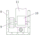
fig. 3 is a side sectional view of the control housing of the present invention;
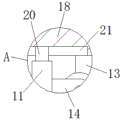
fig. 4 is a partially enlarged view of a in fig. 1 according to the present invention.
In the figure: 1. a base; 2. an air compressor body; 3. a box body; 4. an air inlet pipe; 5. a filter screen; 6. a mesh plate; 7. desiccant particles; 8. a control housing; 9. a first motor; 10. a cam; 11. a movable plate; 12. an equipment box; 13. an adjustment housing; 14. a push wheel; 15. a second motor; 16. a stirring rod; 17. a spring; 18. a partition plate; 19. a fan; 20. a limiting block; 21. a limiting groove.
Detailed Description
The technical solutions in the embodiments of the present invention will be described clearly and completely with reference to the accompanying drawings in the embodiments of the present invention, and it is obvious that the described embodiments are only some embodiments of the present invention, not all embodiments. Based on the embodiments in the present invention, all other embodiments obtained by a person skilled in the art without creative work belong to the protection scope of the present invention.
Referring to fig. 1-4, a screw air compressor unit comprises a base 1, an air compressor body 2 fixedly connected to the left side of the top of the base 1, a box 3 fixedly connected to the right side of the top of the base 1, an air inlet pipe 4 communicated with the bottom of the right side of the box 3, a filter screen 5 fixedly connected between the top and the bottom of the inner cavity of the air inlet pipe 4, a mesh plate 6 fixedly connected to the bottom of the inner cavity of the box 3, desiccant particles 7 arranged at the bottom of the mesh plate 6, a control housing 8 fixedly connected to the left side of the top of the mesh plate 6, a first motor 9 fixedly connected to the rear side of the inner cavity of the control housing 8, a cam 10 fixedly connected to the front side of the output end of the first motor 9, a movable plate 11 arranged on the right side of the cam 10, an equipment box 12 arranged on the right side of the movable plate 11, an adjusting housing 13 fixedly connected to the top of the equipment box 12, a push wheel 14 arranged in the inner cavity of the adjusting housing 13, and a left side of the push wheel 14 fixedly connected to the movable plate 11, the top of the inner cavity of the equipment box 12 is fixedly connected with a second motor 15, the bottom of the output end of the second motor 15 is fixedly connected with a stirring rod 16, the bottom of the stirring rod 16 penetrates through the bottom of the mesh plate 6, a spring 17 is sleeved on the surface of the stirring rod 16 and positioned at the top of the mesh plate 6, a partition plate 18 is fixedly connected at the top between two sides of the inner cavity of the box body 3, the top of the partition plate 18 is fixedly connected with a fan 19, an air outlet at the left side of the fan 19 penetrates through the inner cavity of the air compressor body 2, an air inlet at the right side of the fan 19 penetrates through the bottom of the partition plate 18, the left side of the front surface of the air compressor body 2 is movably connected with an access door through a hinge, a heat dissipation opening is arranged at the front side of the heat dissipation opening, a protective net is arranged at the front side of the heat dissipation opening, an opening matched with the stirring rod 16 is arranged at the top of the mesh plate 6, and the front side of the cam 10 is movably connected with the inner wall of the control shell 8 through a bearing, the right side of the top of the mesh plate 6 is fixedly connected with a sliding rod, the surface of the sliding rod is sleeved with a sliding sleeve, the left side of the sliding sleeve is fixedly connected with the equipment box 12, the top of the movable plate 11 is fixedly connected with a limiting block 20, the left side of the bottom of the partition plate 18 is provided with a limiting groove 21 matched with the limiting block 20 for use, the top and the bottom of the spring 17 are respectively fixedly connected with the equipment box 12 and the mesh plate 6, the top of the front surface of the box body 3 is fixedly connected with a controller, the bottom of the left side of the inner cavity of the control shell 8 is fixedly connected with a sliding rail, the surface of the sliding rail is sleeved with a sliding block, the top of the sliding block is fixedly connected with the movable plate 11, through the arrangement of the air inlet pipe 4 and the filter screen 5, external air can be conveyed into the box body 3, dust in the air can be filtered, and moisture in the air can be adsorbed through the arrangement of the desiccant particles 7, through setting up cam 10, can with the service position of first motor 9 cooperation control fly leaf 11 and push wheel 14, through setting up adjusting housing 13, can cooperate the use height of controlgear case 12 and puddler 16 with push wheel 14, through setting up puddler 16, can stir desiccant granule 7, make it fully contact with the air, through setting up fan 19, can send the air after the drying into air compressor machine body 2, through setting up desiccant granule 7, first motor 9, cam 10, fly leaf 11, adjusting housing 13, push wheel 14, second motor 15, puddler 16, spring 17, baffle 18 and fan 19, the problem of current air compressor machine group does not have dehumidification dampproofing function has been solved, this screw air compressor machine group, possess the advantage of dehumidification dampproofing function, be worth promoting.
During the use, when needs dispel the heat to air compressor body 2, open fan 19, outside air passes through intake pipe 4 and gets into inside box 3, make outside air and drier granule 7 contact, open first motor 9 and second motor 15 simultaneously, second motor 15 drives the puddler 16 rotation and stirs drier granule 7, second motor 15 drives the inclined plane of fly leaf 11 extrusion adjusting shell 13 inner chamber with cam 10 cooperation afterwards, make adjusting shell 13 drive equipment box 12 extrusion spring 17, and make puddler 16 up-and-down reciprocating motion, through stirring drier granule 7, make air and drier granule 7 fully contact, air after the drying is sent into air compressor body 2 through the cooperation of fan 19, through making the air in the air compressor body 2 flow fast, increase the radiating effect of air compressor body 2, prevent outside humid air simultaneously and get into inside air compressor body 2.
Although embodiments of the present invention have been shown and described, it will be appreciated by those skilled in the art that various changes, modifications, substitutions and alterations can be made in these embodiments without departing from the principles and spirit of the invention, the scope of which is defined in the appended claims and their equivalents.
Claims (7)
1. The utility model provides a screw air compressor unit, includes base (1), its characterized in that: the air compressor comprises a base (1), an air compressor body (2) is fixedly connected to the left side of the top of the base (1), a box body (3) is fixedly connected to the right side of the top of the base (1), an air inlet pipe (4) is communicated with the bottom of the right side of the box body (3), a filter screen (5) is fixedly connected between the top and the bottom of an inner cavity of the air inlet pipe (4), a mesh plate (6) is fixedly connected to the bottom of the inner cavity of the box body (3) between the two sides, desiccant particles (7) are arranged at the bottom of the mesh plate (6), a control shell (8) is fixedly connected to the left side of the top of the mesh plate (6), a first motor (9) is fixedly connected to the rear side of the inner cavity of the control shell (8), a cam (10) is fixedly connected to the front side of the output end of the first motor (9), a movable plate (11) is arranged on the right side of the cam (10), a device box (12) is arranged on the right side of the movable plate (11), a regulating shell (13) is fixedly connected to the top of the device box (12), a pushing wheel (14) is arranged in the inner cavity of the regulating shell (13), a second motor (15) is fixedly connected to the top of the stirring rod (15), the bottom of puddler (16) runs through to the bottom of mesh board (6), the top cover that the surface of puddler (16) just is located mesh board (6) is equipped with spring (17), top fixedly connected with baffle (18) between box (3) inner chamber both sides, the top fixedly connected with fan (19) of baffle (18), the inner chamber to air compressor machine body (2) is run through to the air outlet on fan (19) left side, the air intake on fan (19) right side runs through to the bottom of baffle (18).
2. The screw air compressor unit of claim 1, wherein: the left side on the front surface of the air compressor body (2) is movably connected with an access door through a hinge, a heat dissipation opening is formed in the front side of the access door, and a protective net is arranged on the front side of the heat dissipation opening.
3. The screw air compressor unit of claim 1, wherein: the top of mesh board (6) is seted up with puddler (16) cooperation use opening, the front side of cam (10) passes through bearing swing joint with the inner wall of control shell (8).
4. The screw air compressor unit of claim 1, wherein: the right side fixedly connected with slide bar at mesh board (6) top, the surface cover of slide bar is equipped with the sliding sleeve, the left side and the equipment box (12) fixed connection of sliding sleeve.
5. The screw air compressor unit of claim 1, wherein: the top fixedly connected with stopper (20) of fly leaf (11), spacing groove (21) that cooperate with stopper (20) and use have been seted up to the left side of baffle (18) bottom.
6. The screw air compressor unit of claim 1, wherein: the top and the bottom of the spring (17) are respectively fixedly connected with the equipment box (12) and the mesh plate (6), and the top of the front surface of the box body (3) is fixedly connected with a controller.
7. The screw air compressor unit of claim 1, wherein: the bottom of the left side of the inner cavity of the control shell (8) is fixedly connected with a sliding rail, a sliding block is sleeved on the surface of the sliding rail, and the top of the sliding block is fixedly connected with a movable plate (11).
Priority Applications (1)
| Application Number | Priority Date | Filing Date | Title |
|---|---|---|---|
| CN202222414952.0U CN218479923U (en) | 2022-09-13 | 2022-09-13 | Screw air compressor unit |
Applications Claiming Priority (1)
| Application Number | Priority Date | Filing Date | Title |
|---|---|---|---|
| CN202222414952.0U CN218479923U (en) | 2022-09-13 | 2022-09-13 | Screw air compressor unit |
Publications (1)
| Publication Number | Publication Date |
|---|---|
| CN218479923U true CN218479923U (en) | 2023-02-14 |
Family
ID=85166956
Family Applications (1)
| Application Number | Title | Priority Date | Filing Date |
|---|---|---|---|
| CN202222414952.0U Active CN218479923U (en) | 2022-09-13 | 2022-09-13 | Screw air compressor unit |
Country Status (1)
| Country | Link |
|---|---|
| CN (1) | CN218479923U (en) |
-
2022
- 2022-09-13 CN CN202222414952.0U patent/CN218479923U/en active Active
Similar Documents
| Publication | Publication Date | Title |
|---|---|---|
| CN219432056U (en) | Dry oil-free energy-saving screw air compressor | |
| CN104266273A (en) | Bidirectional air intake tower type air purifier structure | |
| CN209401987U (en) | The new structure of distribution box | |
| CN111509951B (en) | Frequency converter | |
| CN203384056U (en) | Case-packed type screw air compressor | |
| CN110966699A (en) | Computer lab that usable natural resources cooled down to communication base station equipment | |
| CN218672582U (en) | Fresh air device and air conditioner | |
| CN214901854U (en) | Intelligent power cabinet | |
| CN112667050B (en) | High radiating big data all-in-one | |
| CN218920872U (en) | An integrated inspection control cabinet | |
| CN217898184U (en) | Air compressor for thermal power plant | |
| CN212746740U (en) | Rotary dehumidifier | |
| CN215421143U (en) | Intelligent network cabinet with quick fingerprint authentication function | |
| CN213808157U (en) | An energy-saving and environmentally friendly exhaust fan with good stability | |
| CN209558606U (en) | Intelligent control fresh air fan | |
| CN218936576U (en) | Energy-saving compressed air purifier | |
| CN112648688A (en) | Central fresh air dehumidifier | |
| CN220023465U (en) | Moistureproof control cabinet | |
| CN211266085U (en) | Industrial electrical control cabinet of wisdom | |
| CN219803486U (en) | Energy-saving fume chamber | |
| CN221748805U (en) | A communication cabinet with adjustable internal space | |
| CN220822263U (en) | Self-dehumidifying power distribution cabinet | |
| CN208253766U (en) | A kind of small-sized dehumidifier convenient for safeguarding | |
| CN116123644B (en) | A kind of indoor ventilation equipment | |
| CN222884958U (en) | Control cabinet of small gate and water pump with standardized design |
Legal Events
| Date | Code | Title | Description |
|---|---|---|---|
| GR01 | Patent grant | ||
| GR01 | Patent grant |