CN218479272U - Water conservancy construction waterproof drainage device - Google Patents
Water conservancy construction waterproof drainage device Download PDFInfo
- Publication number
- CN218479272U CN218479272U CN202222624975.4U CN202222624975U CN218479272U CN 218479272 U CN218479272 U CN 218479272U CN 202222624975 U CN202222624975 U CN 202222624975U CN 218479272 U CN218479272 U CN 218479272U
- Authority
- CN
- China
- Prior art keywords
- fixed
- box body
- water conservancy
- waterproof
- drainage device
- Prior art date
- Legal status (The legal status is an assumption and is not a legal conclusion. Google has not performed a legal analysis and makes no representation as to the accuracy of the status listed.)
- Active
Links
Images


Landscapes
- Sewage (AREA)
Abstract
本申请涉及一种水利施工防水排水装置,包括箱体和排水管,箱体顶部贯穿设置有与箱体固定的下水管,下水管内壁固定有上过滤网,箱体内设有用于刷洗上过滤网的刷洗组件,刷洗组件包括与箱体内壁固定的固定板、转动安装于固定板上的竖杆以及与竖杆上端固定的清洁刷,清洁刷的刷毛与上过滤网上表面抵紧,箱体内还设置有随水流作用运动并用于驱使竖杆转动的动力组件。本申请在下雨时,雨水从下水管向下流动,水流穿过上过滤网上的网孔,动力组件随水流作用运动并驱使竖杆转动,以此使得与竖杆固定的清洁刷转动,从而使得清洁刷的刷毛对上过滤网上的网孔进行清洗,降低了上过滤网上的网孔发生堵塞的概率,减小了工作人员定期清理上过滤网的频率。
The application relates to a waterproof and drainage device for water conservancy construction, which includes a box body and a drain pipe. The top of the box body is provided with a downpipe fixed to the box body. The inner wall of the downpipe is fixed with an upper filter. Net scrubbing assembly, the scrubbing assembly includes a fixed plate fixed to the inner wall of the box, a vertical bar rotatably mounted on the fixed plate, and a cleaning brush fixed to the upper end of the vertical bar. The bristles of the cleaning brush are pressed against the surface of the upper filter net. A power assembly that moves with the action of the water flow and is used to drive the vertical bar to rotate is also provided. In this application, when it rains, the rainwater flows downward from the downpipe, and the water flows through the mesh holes on the upper filter net. The power assembly moves with the water flow and drives the vertical rod to rotate, so that the cleaning brush fixed with the vertical rod rotates, so that The bristles of the cleaning brush clean the meshes on the upper filter net, which reduces the probability of blockage of the meshes on the upper filter net, and reduces the frequency of regular cleaning of the upper filter net by staff.
Description
技术领域technical field
本实用新型涉及水利工程技术领域,特别涉及一种水利施工防水排水装置。The utility model relates to the technical field of water conservancy engineering, in particular to a waterproof and drainage device for water conservancy construction.
背景技术Background technique
水利工程是指为了控制、调节和利用自然界的地面水和地下水,以达到除害兴利的目的而兴建的各种工程,兴修水利可以满足经济社会发展对水资源的需要,可以改善生存环境,促进人类发展。只有修建水利工程,才能控制水流,防止洪涝灾害,并进行水量进行调节和分配,以满足人民生活和生产对水资源的需要。水利工程施工防水排水装置就是其中之一,主要用来防水排水。Water conservancy projects refer to various projects built for the purpose of controlling, regulating and utilizing natural surface water and groundwater to achieve the purpose of eliminating harm and rejuvenating profits. The construction of water conservancy projects can meet the needs of economic and social development for water resources and improve the living environment. promote human development. Only by building water conservancy projects can we control water flow, prevent floods, and adjust and distribute water to meet the needs of people's life and production for water resources. Water conservancy construction waterproof and drainage device is one of them, mainly used for waterproof and drainage.
在公开号为CN213625425U的中国实用新型专利中公开了水利施工防水排水装置,包括箱体,所述箱体的上端中部开有通口,所述箱体的上箱壁左部和上箱壁右部均对称固定连接有放置架,两个所述放置架内共同放置有过滤装置,所述箱体的左箱壁中部穿插固定连接有一号排水管,所述一号排水管的中部设置有电控阀,所述箱体的上箱壁前部固定连接有感应装置,且感应装置位于两个放置架的前方并互不接触,所述箱体的右箱壁下部穿插固定连接有二号排水管。In the Chinese utility model patent whose publication number is CN213625425U, a waterproof and drainage device for water conservancy construction is disclosed, including a box body. All of them are symmetrically fixedly connected with a placement rack, and a filtering device is placed in the two placement racks. The middle part of the left box wall of the box body is inserted and fixedly connected with a No. 1 drain pipe, and the middle part of the No. 1 drain pipe is provided with an electric Control valve, the front part of the upper box wall of the box body is fixedly connected with a sensing device, and the sensing device is located in front of the two placement racks and does not touch each other. The lower part of the right box wall of the box body is inserted and fixedly connected with a No. Tube.
针对上述中的相关技术,发明人认为存在以下缺陷:过滤装置中的上过滤网长时间使用后,容易被堵塞,工作人员需要定期将上过滤网拆卸并清理,操作较为繁琐。In view of the related technologies mentioned above, the inventor believes that there are the following defects: the upper filter in the filter device is easily blocked after being used for a long time, and the staff needs to disassemble and clean the upper filter regularly, which is cumbersome to operate.
实用新型内容Utility model content
为了解决上述问题,本实用新型提供一种水利施工防水排水装置。In order to solve the above problems, the utility model provides a waterproof and drainage device for water conservancy construction.
本实用新型的上述技术目的是通过以下技术方案得以实现的:水利施工防水排水装置,包括箱体以及与箱体侧壁固定并连通的排水管,所述箱体顶部贯穿设置有与箱体固定的下水管,所述下水管内壁固定有上过滤网,所述箱体内设置有用于刷洗上过滤网的刷洗组件;The above-mentioned technical purpose of the utility model is achieved through the following technical solutions: the waterproof and drainage device for water conservancy construction, including a box body and a drainage pipe fixed and communicated with the side wall of the box body, and the top of the box body is provided with a pipe fixed to the box body. The lower water pipe, the upper filter screen is fixed on the inner wall of the lower water pipe, and the scrubbing assembly for scrubbing the upper filter screen is arranged in the box;
所述刷洗组件包括与箱体内壁固定的固定板、与固定板上表面转动连接的竖杆,所述竖杆上端贯穿上过滤网并转动连接,所述刷洗组件还包括与竖杆上端固定的清洁刷,所述清洁刷的刷毛与上过滤网上表面抵紧,所述箱体内还设置有随水流作用运动并用于驱使竖杆转动的动力组件。The brushing assembly includes a fixed plate fixed to the inner wall of the box, and a vertical bar that is rotatably connected to the upper surface of the fixed plate. The upper end of the vertical bar passes through the upper filter screen and is rotatably connected. A cleaning brush, the bristles of the cleaning brush are pressed against the surface of the upper filter net, and a power assembly that moves with the water flow and is used to drive the vertical bar to rotate is also arranged in the box.
通过采用上述技术方案,当下雨时,雨水从下水管向下流动,水流穿过上过滤网上的网孔,动力组件随水流作用运动并驱使竖杆转动,以此使得与竖杆固定的清洁刷转动,从而使得清洁刷的刷毛对上过滤网上的网孔进行清洗,降低了上过滤网上的网孔发生堵塞的概率,减小了工作人员定期清理上过滤网的频率。By adopting the above technical scheme, when it rains, the rainwater flows downward from the downpipe, and the water flows through the mesh holes on the upper filter net. The power assembly moves with the water flow and drives the vertical rod to rotate, so that the cleaning brush fixed with the vertical rod Rotate, so that the bristles of the cleaning brush clean the meshes on the upper filter screen, reducing the probability of blockage of the meshes on the upper filter screen, and reducing the frequency of regular cleaning of the upper filter screen by staff.
进一步的,所述动力组件包括固定套设于竖杆上的从动锥齿轮、与箱体内壁转动连接的横杆、与横杆端部固定并与从动锥齿轮啮合的主动锥齿轮 以及 横杆侧壁固定的动力板,所述下水管下端固定有导水管,所述导水管下端位于动力板的正上方,所述竖杆贯穿导水管并转动连接,所述动力板在自导水管流出的水流冲击下绕横杆转动。Further, the power assembly includes a driven bevel gear fixedly sleeved on the vertical bar, a cross bar rotatably connected to the inner wall of the box, a driving bevel gear fixed to the end of the cross bar and meshed with the driven bevel gear, and a cross bar The power plate fixed on the side wall of the rod, the lower end of the downpipe is fixed with a water guide pipe, the lower end of the water guide tube is located directly above the power plate, the vertical rod passes through the water guide pipe and is connected by rotation, and the power plate flows out from the water guide pipe Under the impact of the water flow, it rotates around the cross bar.
通过采用上述技术方案,当下雨时,雨水从下水管向下流动,水流穿过上过滤网上的网孔后,由于导水管下端正对动力板,使得水流经过导水管并冲击动力板,并使得动力板绕横杆转动,以此使得与横杆固定的主动锥齿轮、与主动锥齿轮啮合的从动锥齿轮、与从动锥齿轮固定的竖杆以及竖杆上端固定的清洁刷发生转动,从而使得清洁刷的刷毛对上过滤网上的网孔进行刷洗,降低了上过滤网上的网孔发生堵塞的概率。By adopting the above technical scheme, when it rains, the rainwater flows downward from the downpipe, and after the water flows through the mesh on the upper filter net, since the lower end of the aqueduct is facing the power plate, the water flows through the aqueduct and impacts on the power plate, causing The power plate rotates around the cross bar, so that the driving bevel gear fixed to the cross bar, the driven bevel gear meshed with the driving bevel gear, the vertical rod fixed with the driven bevel gear and the cleaning brush fixed on the upper end of the vertical rod rotate, Therefore, the bristles of the cleaning brush scrub the mesh holes on the upper filter net, reducing the probability of blockage of the mesh holes on the upper filter net.
进一步的,所述动力板远离横杆的一端一体成型有助力板。Further, a booster plate is integrally formed at the end of the power plate away from the cross bar.
通过采用上述技术方案,助力板能更方便的带动动力板绕横杆转动,提升了清洁刷的刷毛对上过滤网的清洁效率。By adopting the above technical solution, the booster plate can more conveniently drive the power plate to rotate around the cross bar, which improves the cleaning efficiency of the bristles of the cleaning brush on the upper filter screen.
进一步的,所述主动锥齿轮上开设有第一镂空槽,所述从动锥齿轮上开设有第二镂空槽。Further, the driving bevel gear is provided with a first hollow groove, and the driven bevel gear is provided with a second hollow groove.
通过采用上述技术方案,第一镂空槽的设置减轻了主动锥齿轮的重量,第二镂空槽的设置减轻了从动锥齿轮的重量,减小了主动锥齿轮和从动锥齿轮转动过程中的动能损耗,有利于清洁刷对上过滤网进行刷洗。By adopting the above technical solution, the setting of the first hollow groove reduces the weight of the driving bevel gear, and the setting of the second hollow groove reduces the weight of the driven bevel gear, reducing the friction between the driving bevel gear and the driven bevel gear during the rotation process. The loss of kinetic energy is beneficial for the cleaning brush to scrub the upper filter screen.
进一步的,所述下水管内设置有网兜。Further, a net bag is arranged in the downpipe.
通过采用上述技术方案,当下水管内进入树叶、树枝等体积较大的杂物时,网兜对此部分杂物起到了良好的收集作用,有利于工作人员提起网兜并对树叶、树枝等大体积杂物进行清理。By adopting the above-mentioned technical scheme, when large-volume sundries such as leaves and branches enter the downpipe, the net bag has a good effect on collecting this part of sundries, which is helpful for the staff to lift the net bag and remove large-volume sundries such as leaves and branches. things to clean up.
进一步的,所述网兜顶部固定有环形板体,所述环形板体的外径大于下水管的内径,且所述环形板体上表面固定有把手。Further, an annular plate body is fixed on the top of the net bag, the outer diameter of the annular plate body is larger than the inner diameter of the drain pipe, and a handle is fixed on the upper surface of the annular plate body.
通过采用上述技术方案,环形板体可以防止网兜落入排水口内,把手方便工作人员更便捷的提起网兜并清理网兜内的大体积杂物。By adopting the above-mentioned technical scheme, the annular plate body can prevent the net bag from falling into the drain port, and the handle is convenient for the staff to lift the net bag and clean up the bulky debris in the net bag.
进一步的,所述排水管位于箱体内的一端固定有下过滤网。Further, a lower filter net is fixed at one end of the drain pipe located in the box.
通过采用上述技术方案,下过滤网可以有效的防止杂物堵塞排水管,提高排水效率。By adopting the above technical solution, the lower filter screen can effectively prevent sundries from clogging the drainage pipe and improve the drainage efficiency.
进一步的,所述下过滤网呈球形,该球形的直径大于排水管的外径。Further, the lower filter screen is spherical, and the diameter of the spherical shape is larger than the outer diameter of the drain pipe.
通过采用上述技术方案,使得下过滤网的过滤范围扩大,降低了因杂物堆积在下过滤网周围,而使得下过滤网上的网孔发生堵塞的概率降低,有利于箱体内的水从排水管排出。By adopting the above-mentioned technical scheme, the filtering range of the lower filter net is expanded, and the probability of clogging of the mesh holes on the lower filter net due to debris accumulation around the lower filter net is reduced, which facilitates the water in the box to be discharged from the drain pipe .
进一步的,所述箱体内底壁倾斜设置,所述箱体内底壁高度自下过滤网朝向远离排水管的一侧递减。Further, the inner bottom wall of the box is arranged obliquely, and the height of the inner bottom wall of the box decreases gradually from the lower filter net to the side away from the drain pipe.
通过采用上述技术方案,被下过滤网过滤的杂物会由于高度差的原因,聚集在箱体内底壁远离排水管的一侧,降低了因杂物堆积在排水管的进水处而影响排水效率的概率。By adopting the above technical scheme, the sundries filtered by the lower filter will gather on the side of the bottom wall of the box body away from the drain pipe due to the height difference, which reduces the impact on drainage caused by the accumulation of sundries at the water inlet of the drain pipe probability of efficiency.
综上所述,本实用新型具有以下有益效果:In summary, the utility model has the following beneficial effects:
1、本申请中,当下雨时,雨水从下水管向下流动,水流穿过上过滤网上的网孔,动力组件随水流作用运动并驱使竖杆转动,以此使得与竖杆固定的清洁刷转动,从而使得清洁刷的刷毛对上过滤网上的网孔进行清洗,降低了上过滤网上的网孔发生堵塞的概率,减小了工作人员定期清理上过滤网的频率;1. In this application, when it rains, the rainwater flows downward from the downpipe, and the water flows through the mesh holes on the upper filter net. The power assembly moves with the water flow and drives the vertical rod to rotate, so that the cleaning brush fixed with the vertical rod Rotate, so that the bristles of the cleaning brush clean the mesh holes on the upper filter net, reducing the probability of blockage of the mesh holes on the upper filter net, and reducing the frequency of regular cleaning of the upper filter net by staff;
2、本申请中,助力板能更方便的带动动力板绕横杆转动,提升了清洁刷的刷毛对上过滤网的清洁效率;2. In this application, the booster plate can more conveniently drive the power plate to rotate around the cross bar, which improves the cleaning efficiency of the bristles of the cleaning brush on the upper filter;
3、本申请中,当下水管内进入树叶、树枝等体积较大的杂物时,网兜对此部分杂物起到了良好的收集作用,有利于工作人员提起网兜并对树叶、树枝等大体积杂物进行清理。3. In this application, when large-volume debris such as leaves and branches enters the downpipe, the net bag has a good collection effect on this part of the debris, which is beneficial for the staff to lift the net bag and remove large-volume debris such as leaves and branches. things to clean up.
附图说明Description of drawings
图1是本实用新型实施例的整体结构示意图;Fig. 1 is the overall structural representation of the utility model embodiment;
图2是本实用新型实施例的剖面结构示意图;Fig. 2 is the sectional structure schematic diagram of the utility model embodiment;
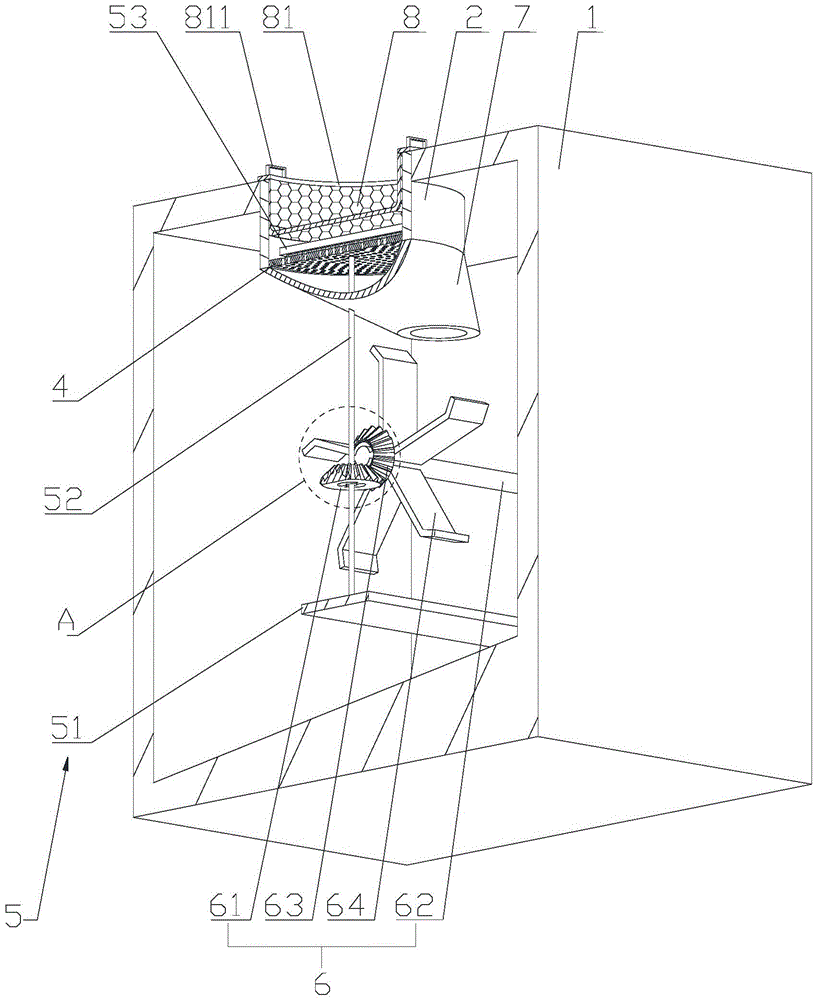
图3是图2中A处的放大示意图;Fig. 3 is the enlarged schematic diagram of place A in Fig. 2;
图4是本实用新型实施例用于凸显下过滤网的结构示意图。Fig. 4 is a schematic structural diagram for highlighting the lower filter net according to the embodiment of the present invention.
图中:1、箱体;2、下水管;3、排水管;4、上过滤网;5、刷洗组件;51、固定板;52、竖杆;53、清洁刷;6、动力组件;61、从动锥齿轮;611、第二镂空槽;62、横杆;63、主动锥齿轮;631、第一镂空槽;64、动力板;641、助力板;7、导水管;8、网兜;81、环形板体;811、把手;9、下过滤网。In the figure: 1. Cabinet; 2. Downpipe; 3. Drainage pipe; 4. Upper filter; 5. Scrubbing component; 51. Fixing plate; 52. Vertical rod; 53. Cleaning brush; 6. Power component; 61 , the driven bevel gear; 611, the second hollow groove; 62, the cross bar; 63, the driving bevel gear; 631, the first hollow groove; 64, the power plate; 641, the booster plate; 81. Annular plate body; 811. Handle; 9. Lower filter screen.
具体实施方式Detailed ways
下面将结合本申请实施例中的附图,对本申请实施例中的技术方案进行清楚、完整地描述;显然,所描述的实施例仅仅是本申请一部分实施例,而不是全部的实施例,基于本申请中的实施例,本领域普通技术人员在没有做出创造性劳动前提下所获得的所有其他实施例,都属于本申请保护的范围。The technical solutions in the embodiments of the application will be clearly and completely described below in conjunction with the accompanying drawings in the embodiments of the application; obviously, the described embodiments are only some of the embodiments of the application, not all of them, based on The embodiments in the present application and all other embodiments obtained by persons of ordinary skill in the art without creative efforts belong to the protection scope of the present application.
如图1-4所示,本申请实施例公开水利施工防水排水装置,包括箱体1、下水管2、排水管3、上过滤网4、刷洗组件5、动力组件6以及导水管7。箱体1为内部中空的长方体形结构,下水管2为竖直设置的圆管状结构,下水管2贯穿设置于箱体1顶部并与箱体1固定连接。排水管3为水平设置的圆管状结构,排水管3设置于箱体1侧壁靠近箱体1内底壁的位置上,排水管3的一端贯穿箱体1侧壁并固定。As shown in Figures 1-4, the embodiment of the present application discloses a waterproof and drainage device for water conservancy construction, including a box body 1, a
上过滤网4为横截面呈圆形的滤网,上过滤网4的轴线与下水管2的轴线重合,上过滤网4侧壁与下水管2内壁靠近下水管2下端的位置固定,上过滤网4能够对从下水管2进入箱体1内的水流进行过滤,降低了进入箱体1内水流中杂物含量,减小了排水管3被杂物堵塞的概率。The
刷洗组件5安装于箱体1内,用于刷洗上过滤网4,刷洗组件5包括固定板51、竖杆52以及清洁刷53。固定板51为水平设置的长方形板状结构,固定板51的一端与箱体1内侧壁固定。竖杆52为竖直设置的圆杆状结构,其轴线与下水管2的轴线重合,竖杆52下端转动安装于固定板51上,竖杆52上端贯穿上过滤网4并转动连接。清洁刷53水平设置,清洁刷53的刷柄底面与竖杆52上端固定,清洁刷53的刷毛与上过滤网4的上表面抵紧。The scrubbing assembly 5 is installed in the box body 1 for scrubbing the
动力组件6安装于箱体1内,随水流作用运动并用于驱使竖杆52转动,动力组件6包括从动锥齿轮61、横杆62、主动锥齿轮63以及动力板64。从动锥齿轮61的轴线与竖杆52的轴线重合,从动锥齿轮61固定套设于竖杆52上。横杆62为水平设置的圆杆状结构,横杆62的一端与箱体1内壁转动连接。主动锥齿轮63的轴线与横杆62的轴线重合,主动锥齿轮63一侧的表面与横杆62端部固定,主动锥齿轮63与从动锥齿轮61啮合。动力板64为板状结构,动力板64的一端与横杆62侧壁固定,动力板64设有多个并关于横杆62的轴线均匀分布。The power assembly 6 is installed in the box body 1 , moves with the water flow and is used to drive the
导水管7为管状结构,导水管7上端与下水管2下端固定,导水管7下端位于动力板64的正上方,竖杆52贯穿导水管7并转动连接,导水管7用于将水流引导对准动力板64并冲击。The
水流进入下水管2后,水流穿过上过滤网4上的网孔后,由于导水管7下端正对动力板64,使得水流经过导水管7并冲击动力板64,并使得动力板64绕横杆62转动,以此使得与横杆62固定的主动锥齿轮63、与主动锥齿轮63啮合的从动锥齿轮61、与从动锥齿轮61固定的竖杆52以及竖杆52上端固定的清洁刷53发生转动,从而使得清洁刷53的刷毛对上过滤网4上的网孔进行刷洗,降低了上过滤网4上的网孔发生堵塞的概率。After the water flow enters the
为了使水流能够顺利冲击动力板64并使得动力板64发生转动,动力板64远离横杆62的一端一体成型有助力板641,助力板641能更方便的带动动力板64绕横杆62转动,提升了清洁刷53的刷毛对上过滤网4的清洁效率。In order to allow the water flow to smoothly impact the
为了降低主动锥齿轮63和从动锥齿轮61的重量,主动锥齿轮63上开设有第一镂空槽631,从动锥齿轮61上开设有第二镂空槽611,第一镂空槽631的设置减轻了主动锥齿轮63的重量,第二镂空槽611的设置减轻了从动锥齿轮61的重量,减小了主动锥齿轮63和从动锥齿轮61转动过程中的动能损耗,更加有利于清洁刷53对上过滤网4进行刷洗。In order to reduce the weight of the driving
为了收集树叶、树枝等大体积杂物,以便于工作人员对杂物进行清理,下水管2内设置有网兜8,网兜8外壁与下水管2内壁抵接,当体积较大的杂物进入下水管2时,网兜8可以有效的进行拦截,以此便于工作人员提起网兜8,并对树叶、树枝等大体积杂物一次性清理。In order to collect large-volume sundries such as leaves and branches, so that the staff can clean up the sundries, a net bag 8 is arranged in the
为了方便工作人员提起网兜8,网兜8顶部固定有环形板体81,环形板体81的外径大于下水管2的内径,且环形板体81上表面固定有把手811,当需要清理网兜8时,工作人员可以抓住把手811提起网兜8并清理网兜8内的大体积杂物。For the convenience of the staff to lift the net pocket 8, the top of the net pocket 8 is fixed with an
为了降低排水管3被杂物堵塞的概率,排水管3位于箱体1内的一端固定有下过滤网9,下过滤网9可以有效的防止杂物堵塞排水管3,提高排水效率。In order to reduce the probability that the
为了降低下过滤网9的网孔被杂物堵塞的概率,下过滤网9呈球形,该球形的直径大于排水管3的外径,使得下过滤网9的过滤范围扩大,降低了因杂物堆积在下过滤网9周围,而使得下过滤网9上的网孔发生堵塞的概率降低,有利于箱体1内的水从排水管3排出。In order to reduce the probability that the mesh holes of the
为了降低杂物堆积在排水管3的进水处影响排水的概率,箱体1内底壁倾斜设置,箱体1内底壁高度自下过滤网9朝向远离排水管3的一侧递减,被下过滤网9过滤的杂物会由于高度差的原因,聚集在箱体1内底壁远离排水管3的一侧,有利于水流顺利从排水管3排出。In order to reduce the probability that debris accumulates in the water inlet of the
本实施例中水利施工防水排水装置的使用原理为:当下雨时,雨水从下水管2向下流动,水流穿过上过滤网4上的网孔,由于导水管7下端正对动力板64,使得水流经过导水管7并冲击动力板64,并使得动力板64绕横杆62转动,以此使得与横杆62固定的主动锥齿轮63、与主动锥齿轮63啮合的从动锥齿轮61、与从动锥齿轮61固定的竖杆52以及竖杆52上端固定的清洁刷53发生转动,从而使得清洁刷53的刷毛对上过滤网4上的网孔进行刷洗,降低了上过滤网4上的网孔发生堵塞的概率,减小了工作人员定期清理上过滤网4的频率。The principle of use of the waterproof and drainage device for water conservancy construction in this embodiment is: when it rains, the rainwater flows downward from the
以上所述仅是本实用新型的优选实施方式,本实用新型的保护范围并不仅局限于上述实施例,凡属于本实用新型思路下的技术方案均属于本实用新型的保护范围。应当指出,对于本技术领域的普通技术人员来说,在不脱离本实用新型原理前提下的若干改进和润饰,这些改进和润饰也应视为本实用新型的保护范围。The above descriptions are only preferred implementations of the present utility model, and the protection scope of the present utility model is not limited to the above-mentioned embodiments, and all technical solutions under the idea of the present utility model all belong to the protection scope of the present utility model. It should be pointed out that for those skilled in the art, some improvements and modifications without departing from the principle of the utility model should also be regarded as the protection scope of the utility model.
Claims (9)
Priority Applications (1)
| Application Number | Priority Date | Filing Date | Title |
|---|---|---|---|
| CN202222624975.4U CN218479272U (en) | 2022-09-30 | 2022-09-30 | Water conservancy construction waterproof drainage device |
Applications Claiming Priority (1)
| Application Number | Priority Date | Filing Date | Title |
|---|---|---|---|
| CN202222624975.4U CN218479272U (en) | 2022-09-30 | 2022-09-30 | Water conservancy construction waterproof drainage device |
Publications (1)
| Publication Number | Publication Date |
|---|---|
| CN218479272U true CN218479272U (en) | 2023-02-14 |
Family
ID=85169638
Family Applications (1)
| Application Number | Title | Priority Date | Filing Date |
|---|---|---|---|
| CN202222624975.4U Active CN218479272U (en) | 2022-09-30 | 2022-09-30 | Water conservancy construction waterproof drainage device |
Country Status (1)
| Country | Link |
|---|---|
| CN (1) | CN218479272U (en) |
-
2022
- 2022-09-30 CN CN202222624975.4U patent/CN218479272U/en active Active
Similar Documents
| Publication | Publication Date | Title |
|---|---|---|
| CN213784561U (en) | Irrigation equipment who has rainwater collection mechanism is used in gardens | |
| CN206828237U (en) | A kind of swimming pool cleaning plant | |
| CN116905610A (en) | Rainwater circulation system for building | |
| CN112681627A (en) | Energy-saving building | |
| CN217870859U (en) | Deodorant device of municipal park sewer | |
| CN215855184U (en) | Green energy-saving rainwater collection and purification device for building | |
| CN216787357U (en) | Anti-blocking structure for rain sewage pipeline | |
| CN214319346U (en) | An environmental protection garden water pool purification device | |
| CN101463704B (en) | Mesh window with automatic ash filtration and self-cleaning function | |
| CN213803183U (en) | Rural sewage is with filtering recovery unit | |
| CN219653795U (en) | Sponge urban rainwater collection device | |
| CN216892646U (en) | Water circulation equipment of otter board filter residue based on green building | |
| CN216136756U (en) | Percolate collecting tank | |
| CN213014472U (en) | A nuclear power plant combined pump room fire-fighting pool layout structure | |
| CN110214705B (en) | Clean environment-friendly bamboo rat breeding device in dead angle is bred to bamboo rat | |
| CN211646553U (en) | Green building rainwater collection auxiliary device | |
| CN213939171U (en) | A water conservation equipment of spraying for landscape | |
| CN221662619U (en) | A filtering device for a water supply system | |
| CN209602132U (en) | A kind of sewage-treatment plant | |
| CN114482225A (en) | A device for ecological restoration and management of soil and water conservation | |
| CN218479615U (en) | Swimming pool robot | |
| CN218779431U (en) | A kind of flowing glass channel | |
| CN103216004B (en) | Device for collecting and storing domestic drainage as fire fighting water | |
| CN222275971U (en) | House construction drainage structures | |
| CN219386909U (en) | Water supply and drainage structure of high-rise building |
Legal Events
| Date | Code | Title | Description |
|---|---|---|---|
| GR01 | Patent grant | ||
| GR01 | Patent grant | ||
| TR01 | Transfer of patent right | ||
| TR01 | Transfer of patent right |
Effective date of registration: 20260402 Address after: 343000 Jiangxi Province, Ji'an City, Jizhou District, Hangsheng Building A Building, 2nd Floor Patentee after: Ji'an Jitai Water Resources and Hydropower Construction Supervision Co.,Ltd. Country or region after: China Address before: 247200 Anhui Province, Chizhou City, Dongzhi County, Dadakou Town, Xinqiao Village, Qiao Group 22.NO Patentee before: Anhui Yikun Construction Engineering Co.,Ltd. Country or region before: China |