CN218478201U - PCB board unloading collating unit - Google Patents
PCB board unloading collating unit Download PDFInfo
- Publication number
- CN218478201U CN218478201U CN202222510475.8U CN202222510475U CN218478201U CN 218478201 U CN218478201 U CN 218478201U CN 202222510475 U CN202222510475 U CN 202222510475U CN 218478201 U CN218478201 U CN 218478201U
- Authority
- CN
- China
- Prior art keywords
- guide
- movable
- assembly
- guide rail
- module
- Prior art date
- Legal status (The legal status is an assumption and is not a legal conclusion. Google has not performed a legal analysis and makes no representation as to the accuracy of the status listed.)
- Active
Links
Images



Landscapes
- Warehouses Or Storage Devices (AREA)
Abstract
本实用新型公开了一种PCB板下料排列装置,包括第一直线模组和控制器,还包括与控制器电连接的移动组件、固定引导组件和活动引导组件,移动组件的两端均设置有第一直线模组,第一直线模组固定安装在机架上,固定引导组件和活动引导组件均安装在移动模组处,固定引导组件与活动引导组件相向设置;该PCB板下料排列装置,通过固定引导组件和活动引导组件出的激光传感器和光电开关,确定PCB板料框的储料槽的位置,再通过第一直线模块和移动组件将第一导轨和第二导轨的导槽与储料槽的位置对应,固定引导组件和活动引导组件即可快速地将生产完成的PCB板引导放置进料框的储料槽内,有效地提高PCB板的下料效率,进而提高PCB板的生产效率。

The utility model discloses a PCB board blanking and arranging device, which comprises a first linear module and a controller, and also includes a moving assembly electrically connected to the controller, a fixed guiding assembly and a movable guiding assembly. A first linear module is provided, the first linear module is fixedly installed on the frame, the fixed guide assembly and the movable guide assembly are installed at the mobile module, and the fixed guide assembly and the movable guide assembly are arranged opposite to each other; the PCB board The unloading arrangement device determines the position of the storage tank of the PCB sheet frame through the laser sensor and photoelectric switch produced by the fixed guide assembly and the movable guide assembly, and then moves the first guide rail and the second guide rail through the first linear module and the moving assembly. The guide groove of the guide rail corresponds to the position of the storage tank. The fixed guide assembly and the movable guide assembly can quickly guide and place the completed PCB board in the storage tank of the feeding frame, effectively improving the PCB board unloading efficiency. Thereby improving the production efficiency of the PCB board.
Description
技术领域technical field
本实用新型涉及PCB生产技术领域,具体为一种PCB板下料排列装置。The utility model relates to the technical field of PCB production, in particular to a PCB blanking and arranging device.
背景技术Background technique
PCB(Printed Circuit Board),中文名称为印制电路板,又称印刷线路板,是重要的电子部件,是电子元器件的支撑体,是电子元器件电气相互连接的载体。由于它是采用电子印刷术制作的,故被称为“印刷”电路板。PCB (Printed Circuit Board), the Chinese name is printed circuit board, also known as printed circuit board, is an important electronic component, a support for electronic components, and a carrier for electrical interconnection of electronic components. Because it is made using electronic printing, it is called a "printed" circuit board.
PCB板是一种相对精密且易损的电子部件,因此在其生产完毕后不能够随意叠放,需要使用相应的料框或其他储存装置进行逐块分离放置,一面PCB板之间相互接触碰撞造成损坏,因此在PCB板生产完毕后,一般需要人工将PCB 板放置进料框的储料槽中,使用这样的方式对PCB板进行下来,生产效率较低,不能满足用户的生产需求。The PCB board is a relatively precise and fragile electronic component, so it cannot be stacked at will after its production is completed. It needs to use the corresponding material frame or other storage device to separate and place it piece by piece, and the PCB boards on one side are in contact with each other. Therefore, after the PCB board is produced, it is generally necessary to manually place the PCB board in the storage tank of the feed frame. Using this method to process the PCB board, the production efficiency is low and cannot meet the production needs of users.
实用新型内容Utility model content
针对现有技术的不足,本实用新型提供了一种PCB板下料排列装置。Aiming at the deficiencies of the prior art, the utility model provides a PCB board blanking and arranging device.
为实现上述目的,本实用新型提供如下技术方案:一种PCB板下料排列装置,包括第一直线模组和控制器,控制器与第一直线模组电连接,还包括与控制器电连接的移动组件、固定引导组件和活动引导组件,所述移动组件的两端均设置有第一直线模组,第一直线模组固定安装在机架上,固定引导组件和活动引导组件均安装在移动模组处,固定引导组件与活动引导组件相向设置,所述固定引导组件包括第一活动板、第一导轨、第一激光传感器和第二光电开关,所述第一活动板与移动组件连接,第一导轨、第一光电开关和第一激光传感器均安装在第一活动板上,第一光电开关和第二激光传感器安装在第一导轨的侧部,所述活动引导组件包括第二活动板、第二直线模组、第二导轨、第二激光传感器和第二光电开关,所述第二活动板与移动组件连接,第二直线模块安装在第二活动板上,第二导轨安装在第二直线模组处,第二光电开关和第二激光传感器安装在第二活动板上且第二光电开关和第二激光传感器位于第二导轨的侧部,所述第一导轨和第二导轨结构相同,第一导轨和第二导轨上均开设有呈漏斗状的导槽。In order to achieve the above purpose, the utility model provides the following technical solutions: a PCB board blanking arrangement device, including a first linear module and a controller, the controller is electrically connected to the first linear module, and also includes a The mobile assembly, the fixed guide assembly and the movable guide assembly are electrically connected. Both ends of the mobile assembly are provided with a first linear module, and the first linear module is fixedly installed on the frame. The fixed guide assembly and the movable guide The components are all installed at the mobile module, and the fixed guide component is arranged opposite to the movable guide component. The fixed guide component includes a first movable plate, a first guide rail, a first laser sensor and a second photoelectric switch. The first movable plate Connected with the moving assembly, the first guide rail, the first photoelectric switch and the first laser sensor are installed on the first movable plate, the first photoelectric switch and the second laser sensor are installed on the side of the first guide rail, and the movable guide assembly It includes a second movable board, a second linear module, a second guide rail, a second laser sensor and a second photoelectric switch, the second movable board is connected with the moving assembly, the second linear module is installed on the second movable board, and the second The second guide rail is installed at the second linear module place, the second photoelectric switch and the second laser sensor are installed on the second movable plate and the second photoelectric switch and the second laser sensor are located at the side of the second guide rail, and the first guide rail The same structure as the second guide rail, both the first guide rail and the second guide rail are provided with funnel-shaped guide grooves.
进一步,所述活动引导组件还包括移动板和移动导轨,所述第二导轨固定安装在移动板处,移动板安装在第二直线模组处,移动导轨固定安装在第二活动板上且移动导轨与移动板滑动连接,移动导轨与第二直线模组的平行设置。Further, the movable guide assembly also includes a moving plate and a moving guide rail, the second guide rail is fixedly installed on the moving plate, the moving plate is installed on the second linear module, and the moving guide rail is fixedly installed on the second movable plate and moves The guide rail is slidingly connected with the moving plate, and the moving guide rail is arranged parallel to the second linear module.
进一步,所述移动组件包括活动架、若干导杆、若干导套、第一驱动模块和第二驱动模块,所述活动架的两端分别与一个第一直线模组连接,移动架内设置有若干杆,第一活动板和第二活动板处均安装有若干导套,导套套设在导杆上且导套与导杆滑动连接,所述第一驱动模块和第二驱动模块均安装在活动架处,第一驱动模块与固定引导组件连接,第二驱动模块与活动引导组件连接。Further, the moving assembly includes a movable frame, several guide rods, several guide sleeves, a first drive module and a second drive module, the two ends of the movable frame are respectively connected with a first linear module, and the movable frame is set There are several rods, and several guide sleeves are installed at the first movable plate and the second movable plate, the guide sleeves are sleeved on the guide rods and the guide sleeves are slidably connected with the guide rods, the first drive module and the second drive module are installed At the movable frame, the first drive module is connected with the fixed guide assembly, and the second drive module is connected with the movable guide assembly.
进一步,所述第一驱动模块包括第一驱动电机和第一丝杆,所述第一驱动电机固定安装在活动架内,第一驱动电机的输出轴与第一丝杆的一端通过联轴器连接,第一丝杆的另一端与活动架靠近固定引导组件的一端转动连接,第一丝杠与导杆平行设置,第一丝杆与第一活动板通过螺纹连接。Further, the first drive module includes a first drive motor and a first screw rod, the first drive motor is fixedly installed in the movable frame, and the output shaft of the first drive motor and one end of the first screw rod pass through a coupling Connection, the other end of the first screw rod is rotationally connected with the end of the movable frame close to the fixed guide assembly, the first screw rod is arranged in parallel with the guide rod, and the first screw rod is connected with the first movable plate by threads.
进一步,所述第二驱动模块包括第二驱动电机和第二丝杆,所述第二驱动电机固定安装在活动架内,第二驱动电机的输出轴与第二丝杆的一端通过联轴器连接,第二丝杆的另一端与活动架靠近活动引导组件的一端转动连接,第二丝杠与导杆平行设置,第二丝杆与第二活动板通过螺纹连接。Further, the second drive module includes a second drive motor and a second screw rod, the second drive motor is fixedly installed in the movable frame, and the output shaft of the second drive motor and one end of the second screw rod pass through a coupling Connected, the other end of the second screw rod is rotationally connected with the end of the movable frame near the movable guide assembly, the second screw rod is arranged in parallel with the guide rod, and the second screw rod is connected with the second movable plate by threads.
进一步,所述第一导轨和第二导轨的上方通过支架分别安装有第一气动夹爪和第二气动夹爪。Further, a first pneumatic gripper and a second pneumatic gripper are respectively installed above the first guide rail and the second guide rail through brackets.
与现有技术相比,本实用新型提供了一种PCB板下料排列装置,具备以下Compared with the prior art, the utility model provides a PCB board blanking arrangement device, which has the following
有益效果:Beneficial effect:
该PCB板下料排列装置,通过固定引导组件和活动引导组件出的激光传感器和光电开关,确定PCB板料框的储料槽的位置,再通过第一直线模块和移动组件将第一导轨和第二导轨的导槽与储料槽的位置对应,固定引导组件和活动引导组件即可快速地将生产完成的PCB板引导放置进料框的储料槽内,有效地提高PCB板的下料效率,进而提高PCB板的生产效率。The PCB board unloading and arranging device determines the position of the storage tank of the PCB board material frame through the laser sensor and the photoelectric switch produced by the fixed guide assembly and the movable guide assembly, and then moves the first guide rail through the first linear module and the moving assembly. Corresponding to the position of the guide groove of the second guide rail and the storage tank, the fixed guide assembly and the movable guide assembly can quickly guide and place the completed PCB board into the storage tank of the feeding frame, effectively improving the lowering of the PCB board. Material efficiency, thereby improving the production efficiency of PCB boards.
附图说明Description of drawings
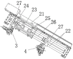
图1为本实用新型的结构图;Fig. 1 is a structural diagram of the utility model;
图2为本实用新型移动组件的结构图;Fig. 2 is a structural diagram of the utility model mobile assembly;
图3为本实用新型固定引导组件的结构图;Fig. 3 is a structural diagram of the fixed guide assembly of the present invention;
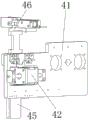
图4为本实用新型活动引导组件的第一视角结构图;Fig. 4 is the structure diagram of the first viewing angle of the movable guide assembly of the present utility model;
图5为本实用新型活动引导组件的第二视角结构图。Fig. 5 is a structural diagram of a second viewing angle of the movable guide assembly of the present invention.
图中:1.第一直线模组,2.移动组件,21.活动架,22.导杆,23.第一驱动电机,24.第一丝杆,25.第二驱动电机,26.第二丝杆,27.导套,3.固定引导组件,31.第一活动板,32.第一气动夹爪,33.第一导轨,34.第一激光传感器, 35.第一光电开关,4.活动引导组件,41.第二活动板,42.第二直线模组,43. 移动板,44.移动导轨,45.第二导轨,46.第二气动夹爪,47.第二激光传感器, 48.第二光电开关。In the figure: 1. The first linear module, 2. The moving component, 21. The movable frame, 22. The guide rod, 23. The first drive motor, 24. The first screw rod, 25. The second drive motor, 26. The second screw, 27. Guide sleeve, 3. Fixed guide assembly, 31. The first movable plate, 32. The first pneumatic gripper, 33. The first guide rail, 34. The first laser sensor, 35. The first photoelectric switch , 4. movable guide assembly, 41. second movable plate, 42. second linear module, 43. movable plate, 44. movable guide rail, 45. second guide rail, 46. second pneumatic gripper, 47. second Laser sensor, 48. A second photoelectric switch.
具体实施方式Detailed ways
下面将结合本实用新型实施例中的附图,对本实用新型实施例中的技术方案进行清楚、完整地描述,显然,所描述的实施例仅仅是本实用新型一部分实施例,而不是全部的实施例。基于本实用新型中的实施例,本领域普通技术人员在没有做出创造性劳动前提下所获得的所有其他实施例,都属于本实用新型保护的范围。The technical solutions in the embodiments of the present invention will be clearly and completely described below in conjunction with the accompanying drawings in the embodiments of the present invention. Obviously, the described embodiments are only part of the embodiments of the present invention, not all of them. example. Based on the embodiments of the present utility model, all other embodiments obtained by persons of ordinary skill in the art without making creative efforts belong to the scope of protection of the present utility model.
实施例Example
请参阅图1至图5,本实用新型提供以下技术方案:Please refer to Fig. 1 to Fig. 5, the utility model provides the following technical solutions:
本PCB板下料排列装置,包括第一直线模组1、控制器、移动组件2、固定引导组件3和活动引导组件4,第一直线模组1和控制器均为现有成熟产品,按需选购即可,在此不再赘述;控制器为本装置的控制元件,其与第一直线模组1、移动组件2、固定引导组件3、活动引导组件4均电连接,用于接收其他电子元件的信号以及控制其他电器的运行。The PCB blanking and arranging device includes a first
移动组件2安装在两个第一直线模组1上,使得移动组件2能够别第一直线模组1驱动移动,固定引导组件3和活动引导组件4均安装在移动组件2内,使得移动组件2在移动时能够携带两引导组件一起运动。The
固定引导组件3主要包括第一活动板31、第一导轨33、第一激光传感器34 和第一光电开关,第一活动板31与移动组件2连接,使得第一活动板31能够被移动组件2驱动移动,第一导轨33固定安装在第一活动板31处,在第一导轨33的侧部安装有第一光电开关和第一激光传感器34,第一光电开关和第一激光传感器34协同作用,用于检测用于存储PCB板的料框处的储料槽的水平和垂直方向的位置,进而确定储料槽的位置,使得第一导轨33处的导槽与料框的储料槽对齐,第一光电开关和第一激光传感器34的安装位置可根据料框的储料槽的宽度大小以及各个储料槽之间的间距适应性调整。The fixed
活动引导组件4主要包括第二活动板41、第二导轨45、第二直线模组42、第二激光传感器47和第二光电开关48,第二直线模组42为现有成熟产品,按需选购即可,在此不再赘述,第二活动板41与移动组件2连接,第二直线模组42安装在第二活动板41处,第二导轨45则安装在第二直线模组42上,使得第二导轨45能够在第二活动板41上移动,在第二导轨45的侧部安装有第二光电开关48和第二激光传感器47,第二光电开关48和第二激光传感器47协同作用,用于检测用于存储PCB板的料框处的储料槽的水平和垂直方向的位置,进而确定储料槽的位置,使得第二导轨45处的导槽与料框的储料槽对齐,第二光电开关48和第二激光传感器47的安装位置可根据料框的储料槽的宽度大小以及各个储料槽之间的间距适应性调整。The
第一导轨33和第二导轨45上的导槽均呈漏斗状,上宽下窄,便于PCB板进入量导轨中,两导轨上的导槽均与料框两侧的储料槽对其后,即可顺利地将 PCB板引导至料框中。The guide grooves on the
活动引导组件4还包括移动板43和移动导轨44,第二安装在移动板43上,移动导轨44安装在移动板43与第二活动板41之间,移动板43与移动导轨44 之间能够相互滑动,移动板43安装在第二直线模组42处,移动板43和移动导轨44的设置能够增强第二导轨45第二活动板41之间的稳定性,使得第二直线模组42驱动第二导轨45在第二活动板41处移动时,第二导轨45移动更加平稳。
移动组件2包括活动架21、若干导杆22、若干导套27、第一驱动模块和第二驱动模块,活动架21为框架结构,活动架21的两端分别安装在一个第一直线模组1上,两个直线模组协同作用即可驱动活动架21及安装在活动架21上的零部件稳定运行;活动架21内设置有多个导杆22,第一活动板31和第二活动板41上均安装有多个导套27,导套27套设在导杆22上与导杆22滑动连接,即使得第一活动板31和第二活动板41能够在导杆22上滑动,第一驱动模块和第二驱动模块均安装在活动架21内,两者分别用于驱动第一活动板31和第二活动板41在导杆22上移动。
第一驱动模块主要由第一驱动电机23和第一丝杆24组成,第一驱动电机 23为动力源,第一驱动电机23固定安装在活动架21内,第一驱动电机23用于驱动第一丝杆24转动,第一丝杆24与第一活动板31通过螺纹连接,进而使得第一丝杆24转动时能够驱动第一活动板31在导杆22上移动。The first driving module mainly is made up of the
同理可知,第二驱动模块主要由第二驱动电机25和第二丝杆26组成,第二驱动电机25为动力源,第二驱动电机25固定安装在活动架21内,第二驱动电机25用于驱动第二丝杆26转动,第二丝杆26与第二活动板41通过螺纹连接,进而使得第二丝杆26转动时能够驱动第二活动板41在导杆22上移动。In the same way, it can be seen that the second drive module is mainly composed of a second drive motor 25 and a second screw mandrel 26, the second drive motor 25 is a power source, the second drive motor 25 is fixedly installed in the
第一导轨33和第二导轨45的上方通过支架分别安装有第一气动夹爪32和第二气动夹爪46,第一气动夹爪32和第二气动夹爪46结构相同,且两气动夹爪优选为二指气动夹爪,两气动夹爪在PCB板下落至两导轨的过程中对PCB板起限位和辅助引导的作用。The top of the
具体实施过程如下:The specific implementation process is as follows:
本PCB板下料排列装置安装在PCB板生产线的下料端,其与相应的机械臂配合使用,机械臂将PCB板搬运至本下料排列装置的上方,随后本装置即可将生产完毕的PCB板引导放置进料框的储料槽中;本装置运行时,各模组、模块、组件协同作用,固定引导组件3的第一光电开关和第一激光传感器34将气动,检测料框的初始储料槽的位置,第一光电开关和第一激光传感器34实时将相应的检测信息回传至控制器中,控制器识别到检测信号后,控制第一直线模组1、第一驱动模块工作,移动固定引导组件3的位置,使得固定引导组件3的第一导轨33上的导槽与料框的初始储料槽对齐;随后活动引导组件4的第二光电开关48与第二激光传感器47协同作用,实时检测料框的初始储料槽另一端的位置,控制器则控制第二驱动模块和第二驱动模组移动第二导轨45的位置,使得第二导轨45上的导槽与料框处的储料槽对齐;当固定引导组件3与活动引导组件4确定初始放料位置后,第一直线模组1驱动移动组件2移动至预定的接料位置,使得固定引导模组和移动引导模组移动至预定的接料位,随后相应的运料机械臂则将生产好的PCB板搬运至第一导轨33和第二导轨45之间,由于第一导轨33和第二导轨45上的导槽呈漏斗状的上宽下窄的结构,因此PCB板可便捷快速地进入至两导轨处,随后第一气动夹爪32和第二气动夹爪46将PCB 板夹持住,使得PCB板被放置在两导轨中,随后第一直线模组1启动,将活动引导组件4和固定引导组件3移动至料框的储料槽处,第一导轨33和第二导轨 45则运动至初始放料位置,同时根据各传感器的检测信息实时调整位置,接着松开第一夹爪和第二夹爪,位于第一导轨33和第二导轨45内的PCB板即可顺利地进入至料框的储料槽中,接着在各传感器的作用下,依次将料框内的各个储料槽中填充PCB板。The PCB blanking arrangement device is installed at the blanking end of the PCB board production line, and it is used in conjunction with the corresponding mechanical arm. The mechanical arm transports the PCB board to the top of the blanking arrangement device, and then the device can complete the production. The PCB board is guided and placed in the storage tank of the feed frame; when the device is running, the modules, modules, and components work together, and the first photoelectric switch and the
该PCB板下料排列装置,通过固定引导组件3和活动引导组件4出的激光传感器和光电开关,确定PCB板料框的储料槽的位置,再通过第一直线模块和移动组件2将第一导轨33和第二导轨45的导槽与储料槽的位置对应,固定引导组件3和活动引导组件4即可快速地将生产完成的PCB板引导放置进料框的储料槽内,有效地提高PCB板的下料效率,进而提高PCB板的生产效率。The PCB blanking and arranging device determines the position of the storage tank of the PCB board material frame through the laser sensor and the photoelectric switch of the fixed
最后应说明的是:以上所述仅为本实用新型的优选实施例而已,并不用于限制本实用新型,尽管参照前述实施例对本实用新型进行了详细的说明,对于本领域的技术人员来说,其依然可以对前述各实施例所记载的技术方案进行修改,或者对其中部分技术特征进行等同替换。凡在本实用新型的精神和原则之内,所作的任何修改、等同替换、改进等,均应包含在本实用新型的保护范围之内。Finally, it should be noted that: the above is only a preferred embodiment of the utility model, and is not intended to limit the utility model, although the utility model has been described in detail with reference to the foregoing embodiments, for those skilled in the art , it is still possible to modify the technical solutions described in the foregoing embodiments, or perform equivalent replacements for some of the technical features. Any modification, equivalent replacement, improvement, etc. made within the spirit and principles of the present utility model shall be included in the protection scope of the present utility model.
Claims (6)
Priority Applications (1)
| Application Number | Priority Date | Filing Date | Title |
|---|---|---|---|
| CN202222510475.8U CN218478201U (en) | 2022-09-22 | 2022-09-22 | PCB board unloading collating unit |
Applications Claiming Priority (1)
| Application Number | Priority Date | Filing Date | Title |
|---|---|---|---|
| CN202222510475.8U CN218478201U (en) | 2022-09-22 | 2022-09-22 | PCB board unloading collating unit |
Publications (1)
| Publication Number | Publication Date |
|---|---|
| CN218478201U true CN218478201U (en) | 2023-02-14 |
Family
ID=85167713
Family Applications (1)
| Application Number | Title | Priority Date | Filing Date |
|---|---|---|---|
| CN202222510475.8U Active CN218478201U (en) | 2022-09-22 | 2022-09-22 | PCB board unloading collating unit |
Country Status (1)
| Country | Link |
|---|---|
| CN (1) | CN218478201U (en) |
Cited By (1)
| Publication number | Priority date | Publication date | Assignee | Title |
|---|---|---|---|---|
| CN116424852A (en) * | 2023-03-21 | 2023-07-14 | 广州市泰立机电设备有限公司 | A kind of unloading device for PCB board production |
-
2022
- 2022-09-22 CN CN202222510475.8U patent/CN218478201U/en active Active
Cited By (2)
| Publication number | Priority date | Publication date | Assignee | Title |
|---|---|---|---|---|
| CN116424852A (en) * | 2023-03-21 | 2023-07-14 | 广州市泰立机电设备有限公司 | A kind of unloading device for PCB board production |
| CN116424852B (en) * | 2023-03-21 | 2023-10-20 | 广州市泰立机电设备有限公司 | Discharging device for PCB production |
Similar Documents
| Publication | Publication Date | Title |
|---|---|---|
| CN207861360U (en) | NG/OK automatic closing machine | |
| CN219817105U (en) | Face sweep type warp detection equipment | |
| CN206842603U (en) | A kind of silk-screen printing automatic paper feeding localization machine | |
| CN208086750U (en) | Fully automatic stacking board feeding machine | |
| CN111337999B (en) | Automatic tapping detection equipment | |
| CN108161420B (en) | A kind of electronic parking brake mandrel assembly testing equipment | |
| CN212364118U (en) | Two-sided detection machine of 3D copper foil board | |
| CN209624711U (en) | A kind of screen automatic checkout equipment | |
| CN206136470U (en) | A fully automatic plug-in machine | |
| CN217965180U (en) | Spot welding device for reflow soldering of circuit board | |
| CN112478753B (en) | A high-speed material collection system | |
| CN206602096U (en) | The bending detection means of solar battery sheet | |
| CN205050635U (en) | FFC is automatic quick -witted towards type | |
| CN109533848B (en) | Online multilayer circuit board buffer memory equipment | |
| CN218930896U (en) | Automatic paper separating device for PCB production | |
| CN219602748U (en) | Feeding device of flexo printing machine | |
| CN218778344U (en) | An automatic feeding device for acrylic sheets | |
| CN209901766U (en) | Full-automatic liquid crystal display panel clamping feeding machine | |
| CN207844253U (en) | A kind of automatic feeding device for machine tool | |
| CN206927252U (en) | Printed substrate system above and below intelligent robot | |
| CN216606174U (en) | PCB terminal floats high detection device | |
| CN113677094B (en) | Feeding device and feeding method for horizontal electroplating of PCB | |
| CN209972943U (en) | Full-automatic counting and stacking machine for PCB (printed circuit board) | |
| CN210435677U (en) | Electromagnetic feeding screw locking machine system | |
| CN209167162U (en) | A kind of circuit board testing machine |
Legal Events
| Date | Code | Title | Description |
|---|---|---|---|
| GR01 | Patent grant | ||
| GR01 | Patent grant | ||
| CP03 | Change of name, title or address | ||
| CP03 | Change of name, title or address |
Address after: 101, No. 15 Xialiang Wangtaibu Road, Taihe Town, Baiyun District, Guangzhou City, Guangdong Province, 510080 Patentee after: Guangdong Hengtai Lihua Intelligent Equipment Manufacturing Co.,Ltd. Country or region after: China Address before: No. 15, Taihe Town, Baiyun District, Guangzhou City, Guangdong Province, China Patentee before: GUANGZHOU TAILI ELECTROMECHANICAL EQUIPMENT CO.,LTD. Country or region before: China |
|
| CP03 | Change of name, title or address | ||
| CP03 | Change of name, title or address |
Address after: 511365 No. 51, Zhongfu South Road, Zhongxin Town, Zengcheng District, Guangzhou City, Guangdong Province Patentee after: Guangdong Hengtai Lihua Intelligent Equipment Manufacturing Co.,Ltd. Country or region after: China Address before: 101, No. 15 Xialiang Wangtaibu Road, Taihe Town, Baiyun District, Guangzhou City, Guangdong Province, 510080 Patentee before: Guangdong Hengtai Lihua Intelligent Equipment Manufacturing Co.,Ltd. Country or region before: China |