CN218477144U - Boot sleeve machine - Google Patents
Boot sleeve machine Download PDFInfo
- Publication number
- CN218477144U CN218477144U CN202222072576.1U CN202222072576U CN218477144U CN 218477144 U CN218477144 U CN 218477144U CN 202222072576 U CN202222072576 U CN 202222072576U CN 218477144 U CN218477144 U CN 218477144U
- Authority
- CN
- China
- Prior art keywords
- roller
- plastic film
- subassembly
- assembly
- frame
- Prior art date
- Legal status (The legal status is an assumption and is not a legal conclusion. Google has not performed a legal analysis and makes no representation as to the accuracy of the status listed.)
- Active
Links
Images


Landscapes
- Package Closures (AREA)
Abstract
Description
技术领域technical field
本实用新型涉及一种靴套机。The utility model relates to a boot covering machine.
背景技术Background technique
靴套是一种穿戴于脚部的一次性防护用品,通常采用CPE/PE塑料薄膜制做,目前与脚部体形相适配的靴套都是由人工操作模具烫焊生产,生产效率低,人工成本高;一次性靴套一般采用无纺布制成,现有技术中,其生产制作工艺流程为:两层无纺布先一个个进行超声波焊接成型然后再进行一个个裁切,或者先一个个裁切好再进行超声波焊接,由于靴套呈L型,如果通过这种方式制作靴套,那么每只靴套裁切的部分较多,从而导致废料多。Boot cover is a kind of disposable protective equipment worn on the feet. It is usually made of CPE/PE plastic film. At present, the boot cover suitable for the shape of the foot is produced by manual mold welding, and the production efficiency is low. High labor costs; disposable boot covers are generally made of non-woven fabrics. In the prior art, the production process is as follows: two layers of non-woven fabrics are ultrasonically welded and formed one by one and then cut one by one, or first After cutting one by one, ultrasonic welding is carried out. Since the boot cover is L-shaped, if the boot cover is made in this way, more parts will be cut for each boot cover, resulting in a lot of waste.
实用新型内容Utility model content
针对现有技术存在的不足,本实用新型的目的在于提供一种靴套机,该靴套机能够生产效率提高,人工成本降低,且能够精准的实现靴套成型塑料薄膜的把控,减少废料的产生。Aiming at the deficiencies of the existing technology, the purpose of the utility model is to provide a boot cover machine, which can improve production efficiency, reduce labor costs, and can accurately control the plastic film of the boot cover, reducing waste generation.
为实现上述目的,本实用新型提供了如下技术方案:一种靴套机,包括卷料组件和机架,卷料组件和机架并排放置,所述卷料组件包括卷料架,所述卷料架上对称设置有第一卷料辊和第二卷料辊,所述第一卷料辊上设置有第一塑料薄膜,所述第二卷料辊上设置有第二塑料薄膜,第一塑料薄膜和第二塑料薄膜均配置有折边组件和橡皮筋导入组件以及封边组件,第一塑料薄膜和第二塑料薄膜用一侧边均通过折边组件进行折边,橡皮筋导入组件在折边内导入橡皮筋,封边组件对折边处进行封边,封边后的第一塑料薄膜和第二塑料薄膜叠合并通过牵引组件输送到超声波封口组件,所述超声波封口组件用于对封边后的第一塑料薄膜和第二塑料薄膜的前后封边口均封口形成靴套鞋口,对形成靴套鞋口的第一塑料薄膜和第二塑料薄膜通过第一预存料组件运输到平压焊接组件,通过平压焊接组件对形成靴套鞋口的第一塑料薄膜和第二塑料薄膜形成鞋套形状的熔接线,再通过第二预存料组件运输到裁切组件,所述裁切组件沿着靴套形状的熔接线裁切。In order to achieve the above object, the utility model provides the following technical solutions: a shoe cover machine, including a coil material assembly and a frame, the coil material assembly and the frame are placed side by side, the coil material assembly includes a coil material rack, the coil material A first coiling roll and a second coiling roll are arranged symmetrically on the rack, the first coiling roll is provided with a first plastic film, the second coiling roll is provided with a second plastic film, and the first coiling roll is provided with a second plastic film. Both the plastic film and the second plastic film are equipped with a hemming assembly, a rubber band introduction assembly and an edge sealing assembly, the first plastic film and the second plastic film are hemmed by the hemming assembly on one side, and the rubber band introduction assembly is in the The rubber band is introduced into the folded edge, and the edge banding component seals the folded edge, and the first plastic film and the second plastic film after the edge banding are superimposed and transported to the ultrasonic sealing component by the traction component, and the ultrasonic sealing component is used for sealing The front and rear edges of the first plastic film and the second plastic film behind the sides are all sealed to form the shoe opening of the boot cover, and the first plastic film and the second plastic film forming the shoe cover of the boot cover are transported to the flat press welding by the first pre-stocked component The first plastic film and the second plastic film that form the shoe opening of the boot cover form a weld line in the shape of a shoe cover through a flat-press welding component, and then transported to the cutting component through the second pre-stock component, and the cutting component is along the Weld line cut in bootie shape.
进一步的,所述折边组件包括可左右移动的调节辊和起靠板,所述起靠板通过支架设置在调节辊与封边组件之间,所述起靠板包括设置在支架上第一斜向杆,第一斜向杆端部连接有第二斜向杆,当塑料薄膜经过调节辊时,塑料薄膜会垂在调节辊的一侧,下垂部分的塑料薄膜通过第二斜向杆折叠,形成折边空间。Further, the hemming assembly includes an adjustment roller that can move left and right and an abutment plate, and the abutment plate is arranged between the adjustment roller and the edge sealing assembly through a bracket, and the abutment plate includes a first An oblique rod, the end of the first oblique rod is connected with a second oblique rod, when the plastic film passes through the adjustment roller, the plastic film will hang on one side of the adjustment roller, and the plastic film of the drooping part is folded by the second oblique rod , forming a hemming space.
进一步的,所述皮筋导入组件包括多个导向架,所述皮筋沿着导向架方向导入到折边空间内。Further, the elastic band introducing assembly includes a plurality of guide frames, and the elastic band is introduced into the hemming space along the direction of the guide frames.
进一步的,所述平压焊接组件包括机架下方设置有输出件,输出件连接有第一凸轮和第二凸轮,所述第一凸轮和第二凸轮上方均设置有横杆,所述横杆两端均连接有竖杆,机架上方设置有固定板和移动板,所述固定板与机架上端面之间设置有支撑杆,所述固定板四角对应竖杆设置有通孔,所述竖杆均穿设通孔与移动板连接,所述移动板和固定板之间的设置有弹簧,弹簧套设在竖杆上,所述移动板朝向固定板的一端面设置有靴套形状的热压模具,所述输出件启动,第一凸轮和第二凸轮实现上下移动,同步移动板带着热压模具上下移动。Further, the flat pressure welding assembly includes an output member provided under the frame, the output member is connected with a first cam and a second cam, and a cross bar is arranged above the first cam and the second cam, and the cross bar Both ends are connected with vertical rods, a fixed plate and a movable plate are arranged above the frame, a support rod is arranged between the fixed plate and the upper end surface of the frame, and through holes are provided at the four corners of the fixed plate corresponding to the vertical rods. The vertical rods are connected with through holes through holes, and a spring is provided between the movable board and the fixed board, and the spring is sleeved on the vertical rods, and a boot-shaped boot-shaped spring is provided on the end of the movable board facing the fixed board. The hot pressing mold, the output member starts, the first cam and the second cam move up and down, and the synchronous moving plate moves up and down with the hot pressing mold.
进一步的,所述超声波封口焊接组件设置在机架上,所述超声波封口焊接组件包括焊接底座和超声波焊接辊,所述超声波焊接辊上设置有两个焊接条,所述焊接条之间的距离对应封边后的第一塑料薄膜和第二塑料薄膜的前后封边口的距离。Further, the ultrasonic sealing welding assembly is arranged on the frame, the ultrasonic sealing welding assembly includes a welding base and an ultrasonic welding roller, two welding strips are arranged on the ultrasonic welding roller, and the distance between the welding strips Corresponding to the distance between the front and rear edge sealing openings of the first plastic film and the second plastic film after edge sealing.
进一步的,裁切组件设置在机架上,所述裁切组件包括底辊和切刀辊,所述切刀辊的圆周面上设置有切刀。Further, the cutting assembly is arranged on the frame, and the cutting assembly includes a bottom roller and a cutter roller, and a cutter is arranged on the peripheral surface of the cutter roller.
进一步的,所述封边组件包括封边底座和封边辊,所述封边辊上设置有焊接齿,焊接齿与封边底座相接触。Further, the edge banding assembly includes an edge banding base and an edge banding roller, the edge banding roller is provided with welding teeth, and the welding teeth are in contact with the edge banding base.
进一步的,所述第一预存料组件和第二预存料组件均设置在机架上,第一预存料组件和第二预存料组件对应机架的位置设置有通槽,所述第一预存料组件和第二预存料组件均包括前后导辊组以及导辊组之间的升降辊,导辊组包括第一导辊和第二导辊,所述第一导辊和第二导辊并列设置,第二导辊通过支架设置有定辊,定辊与升降辊距离为预存料的面积。Further, the first pre-storage component and the second pre-storage component are both arranged on the frame, and the positions of the first pre-storage component and the second pre-storage component are provided with through slots corresponding to the frame, and the first pre-storage component Both the assembly and the second pre-storage assembly include front and rear guide roller groups and lift rollers between the guide roller groups, the guide roller group includes a first guide roller and a second guide roller, and the first guide roller and the second guide roller are arranged side by side , the second guide roller is provided with a fixed roller through the bracket, and the distance between the fixed roller and the lifting roller is the area of the pre-stored material.
进一步的,所述牵引组件包括第一牵引辊和第二牵引辊。Further, the traction assembly includes a first traction roller and a second traction roller.
本实用新型的有益效果:The beneficial effects of the utility model:
1、通过折边组件和橡皮筋导入组件,折边组件包括可左右移动的调节辊实现折边宽度的调整,再通过起靠板实现折边空间,在形成折边空间时,橡皮筋通过导向架实现导向防止偏移,橡皮筋通过惯性以及牵引力沿着导向架导入到折边空间,与现有技术相比减少了驱动橡皮筋导入的组件,降低了生产成本。1. The hemming assembly and the rubber band are introduced into the assembly. The hemming assembly includes adjusting rollers that can move left and right to adjust the hemming width, and then realize the hemming space through the lifting board. When the hemming space is formed, the rubber band passes through the guide The frame is guided to prevent deviation, and the rubber band is guided into the hemming space along the guide frame through inertia and traction. Compared with the prior art, the number of components driving the introduction of the rubber band is reduced, and the production cost is reduced.
2、该靴套机自动完成靴套生产,具有自动化程度高,生产效率高,靴套质量好的优点,精准把控材料,减少废料的产生。2. The boot cover machine automatically completes the production of boot covers, which has the advantages of high automation, high production efficiency, and good quality of boot covers. It can accurately control materials and reduce waste.
附图说明Description of drawings
图1为靴套机的示意图;Fig. 1 is the schematic diagram of boot cover machine;
图2为折边组件的示意图;Fig. 2 is the schematic diagram of folding assembly;
图3为第一预存料组件/第二预存料组件的示意图;Fig. 3 is the schematic diagram of the first pre-stored material assembly/the second pre-stored material assembly;
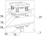
图4为平压焊接组件的示意图。Fig. 4 is a schematic diagram of a flat-press welded assembly.
附图标记:1、卷料组件;11、卷料架;12、第一卷料辊;13、第二卷料辊;2、机架;3、折边组件;31、调节辊;32、起靠板;321、第一斜向杆;322、第二斜向杆;33、支架;4、橡皮筋导入组件;41、导向架;5、封边组件;51、封边底座;52、封边辊;6、超声波封口组件;61、焊接底座;62、超声波焊接辊;63、焊接条;7、平压焊接组件;71、第一凸轮;72、第二凸轮;73、横杆;74、竖杆;75、固定板;76、移动板;77、热压模具;8、第一预存料组件;9、第二预存料组件;10、裁切组件;101、底辊;102、切刀辊;14、牵引组件;141、第一牵引辊;142、第二牵引辊。Reference signs: 1. Coil assembly; 11. Coil rack; 12. First coil roll; 13. Second coil roll; 2. Rack; 3. Hemming assembly; 31. Adjusting roller; 32. 321, the first slanting bar; 322, the second slanting bar; 33, the bracket; 4, the rubber band introduction assembly; 41, the guide frame; 5, the edge banding assembly; 51, the edge banding base; 52, Edge banding roller; 6. Ultrasonic sealing assembly; 61. Welding base; 62. Ultrasonic welding roller; 63. Welding strip; 7. Flat-press welding assembly; 71. First cam; 72. Second cam; 74, vertical bar; 75, fixed plate; 76, movable plate; 77, hot pressing mold; 8, first pre-storage component; 9, second pre-storage component; 10, cutting component; 101, bottom roller; 102, Cutter roller; 14, traction assembly; 141, first traction roller; 142, second traction roller.
具体实施方式Detailed ways
为更进一步阐述本实用新型为实现预定实用新型目的所采取的技术手段及功效,以下结合附图及较佳实施例,对依据本实用新型的具体实施方式、结构、特征及其功效,详细说明如后。In order to further explain the technical means and effects of the utility model to achieve the intended purpose of the utility model, the specific implementation, structure, features and effects of the utility model will be described in detail below in conjunction with the accompanying drawings and preferred embodiments. As later.
参照图1至图4所示,本实施例的一种靴套机,包括卷料组件1和机架2,卷料组件1和机架2并排放放置,所述卷料组件1包括卷料架11,所述卷料架11上对称设置有第一卷料辊12和第二卷料辊13,所述第一卷料辊12上设置有第一塑料薄膜,所述第二卷料辊13上设置有第二塑料薄膜,第一塑料薄膜和第二塑料薄膜同一侧边均通过折边组件3进行折边,橡皮筋导入组件4在折边内导入橡皮筋,封边组件5对折边处进行封边,封边后的第一塑料薄膜和第二塑料薄膜叠合并通过牵引组件14输送到超声波封口组件6,所述超声波封口组件6用于对封边后的第一塑料薄膜和第二塑料薄膜的前后封边口均封口形成靴套鞋口,对形成靴套鞋口的第一塑料薄膜和第二塑料薄膜通过第一预存组料运输到平压焊接组件7,通过平压焊接组件7对形成靴套鞋口的第一塑料薄膜和第二塑料薄膜形成靴套形状的熔接线,再通过第二预存料组件9运输到裁切组件10,所述裁切组件10沿着靴套形状的熔接线裁切。Referring to Fig. 1 to Fig. 4, a kind of boot cover machine of the present embodiment includes a
在上述实施例的基础上,所述折边组件3包括可左右移动的调节辊31和起靠板32,所述起靠板32通过支架33设置在调节辊31与封边组件5之间,所述起靠板32包括设置在支架33上第一斜向杆321,第一斜向杆321端部连接有第二斜向杆322,当塑料薄膜经过调节辊31时,塑料薄膜会垂在调节辊31的一侧,下垂部分的塑料薄膜通过第二斜向杆322折叠,形成折边空间。On the basis of the above embodiments, the hemming assembly 3 includes an adjusting
在上述实施例的基础上,所述皮筋导入组件包括多个导向架41,所述皮筋沿着导向架41方向导入到折边空间内。On the basis of the above embodiments, the elastic band introducing assembly includes a plurality of guide frames 41 , and the elastic band is introduced into the hemming space along the direction of the guide frames 41 .
在上述实施例的基础上,所述平压焊接组件7包括机架2下方设置有输出件,输出件连接有第一凸轮71和第二凸轮72,所述第一凸轮71和第二凸轮72上方均设置有横杆73,所述横杆73两端均连接有竖杆74,机架2上方设置有固定板75和移动板76,所述固定板75与机架2上端面之间设置有支撑杆,所述固定板75四角对应竖杆74设置有通孔,所述竖杆74均穿设通孔与移动板76连接,所述移动板76和固定板75之间设置有弹簧,弹簧套设在竖杆74上,所述移动板76朝向固定板75的一端面设置有靴套形状的热压模具77,所述输出件启动,第一凸轮71和第二凸轮72实现上下移动,同步移动板76带着热压模具77上下移动。On the basis of the above-mentioned embodiments, the flat-
在上述实施例的基础上,所述超声波封口焊接组件设置在机架2上,所述超声波封口焊接组件包括焊接底座61和超声波焊接辊62,所述超声波焊接辊62上设置有两个焊接条63,所述焊接条63之间的距离对应封边后的第一塑料薄膜和第二塑料薄膜的前后封边口的距离。On the basis of the above-mentioned embodiments, the ultrasonic sealing welding assembly is arranged on the
在上述实施例的基础上,所述裁切组件10设置在机架2上,所述裁切组件10包括底辊101和切刀辊102,所述切刀辊102的圆周面上设置有切刀。On the basis of the above embodiments, the cutting assembly 10 is arranged on the
在上述实施例的基础上,所述封边组件5包括封边底座51和封边辊52,所述封边辊52上设置有焊接齿,焊接齿与封边底座51相接触。On the basis of the above embodiments, the
在上述实施例的基础上,所述第一预存料组件8和第二预存料组件9均设置在机架2上,第一预存料组件8和第二预存料组件9对应机架2的位置设置有通槽,所述第一预存料组件8和第二预存料组件9均包括前后导辊组以及导辊组之间的升降辊,导辊组包括第一导辊和第二导辊,所述第一导辊和第二导辊并列设置,第二导辊通过支架33设置有定辊,定辊与升降辊距离为预存料的面积。On the basis of the above embodiment, the first
在上述实施例的基础上,所述牵引组件14包括第一牵引辊141和第二牵引辊142。On the basis of the above embodiments, the
上述改进具体为:如图1至图4所示:包括卷料组件1和机架2,卷料组件1和机架2并排放置,卷料组件1包括卷料架11,卷料架11上对称设置有第一卷料辊12和第二卷料辊13,卷料架11为气动升降,能够调整第一卷料辊12、第二卷料辊13的位置以及能够自动纠偏第一卷料辊11和第二卷料辊13对齐,使后续的第一塑料薄膜和第二塑料薄膜能够对齐叠合和对折边组件3的折边位置进行自动修正,第一卷料辊12上设置有第一塑料薄膜,第二卷料辊13上设置有第二塑料薄膜,第一塑料薄膜和第二塑料薄膜均配置有折边组件3和橡皮筋导入组件4以及封边组件5,折边组件3包括可左右移动的调节辊31和起靠板32,起靠板32通过支架33设置在调节辊31与封边组件5之间,起靠板32包括设置在支架33上的第一斜向杆321,第一斜向杆321端部连接有第二斜向杆322,根据折边的宽度移动调节辊31的位置,确定塑料薄膜下垂的宽度,下垂的塑料薄膜通过第二斜向杆322将下垂塑料薄膜折叠形成折叠层,在形成折边空间时,皮筋最开始手动导入到折边空间内,后续的皮筋会通过惯性和牵引力沿着导向架41的方向自动导入到折边空间内,含有皮筋的折叠层会通过封边组件5与塑料薄膜封边,封边组件5包括封边底辊101和封边辊52,封边辊52上设置有焊接齿,封边后的第一塑料薄膜和第二塑料薄膜叠合通过牵引组件14运输到超声波封口焊接组件,牵引组件14包括第一牵引辊141和第二牵引辊142,超声波封口焊接组件包括焊接底座61和超声波焊接辊62,超声波焊接辊62上设置有两个焊接条63,两个焊接条63之间的距离对应靴口的直径,将第一塑料薄膜和第二塑料薄膜按照靴口直径对封边口进行封口,第一塑料薄膜和第二塑料薄膜形成靴口,第一预存料组件8和第二预存料组件9均包括前后导辊组以及前后导辊组之间的升降辊,导辊组包括第一导辊和第二导辊,第一导辊和第二导辊并列设置,第二导辊通过支架33设置有定辊,定辊之间设置有升降辊,定辊和升降辊之间是预留一个靴套的位置,由于平压焊接组件7在塑料薄膜上焊接靴套形状时需要停顿,停顿之后通过定辊和升降辊进行预存,通过平压焊接组件7将塑料薄膜形成靴套形状的熔接线,平压焊接组件7包括输出件,输出件为电机,输出件连接有第一凸轮71和第二凸轮72,第一凸轮71和第二凸轮72上方均设置有横杆73,所述横杆73两端均连接有竖杆74,机架2上方设置有固定板75和移动板76,固定板75与机架2上端面之间设置有支撑杆,固定板75四角对应竖杆74设置有通孔,竖杆74均穿设通孔与移动板76连接,移动板76和固定板75之间设置有弹簧,弹簧套设在竖杆74上,移动板76朝向固定板75的一端面设置有靴套形状的热压模具77,热压模具77为靴套形状,输出件启动,第一凸轮71和第二凸轮72实现上下移动,同步移动板76带着热压模具77上下移动,通过第二预存料组件9进行预留,因为裁切组件10对应靴套形状的熔接线裁切时也是需要时间停顿,在停顿中通过第二预存料组件9进行预留,裁切组件10包括底辊101和切刀辊102,切刀辊102上的圆周面上设置有切刀,切刀沿着靴套形状的熔接线裁切形成完整的靴套,通过折边组件3和橡皮筋导入组件4,折边组件3包括可左右移动的调节辊31实现折边宽度的调整,再通过起靠板32实现折边空间,在形成折边空间时,橡皮筋通过导向架41实现导向防止偏移,橡皮筋通过惯性以及牵引力沿着导向架41导入到折边空间,与现有技术相比减少了驱动橡皮筋导入的组件,降低了生产成本。The above improvements are specifically as follows: as shown in Figures 1 to 4: comprising a
以上所述,仅是本实用新型的较佳实施例而已,并非对本实用新型作任何形式上的限制,虽然本实用新型已以较佳实施例揭示如上,然而并非用以限定本实用新型,任何本领域技术人员,在不脱离本实用新型技术方案范围内,当可利用上述揭示的技术内容做出些许更动或修饰为等同变化的等效实施例,但凡是未脱离本实用新型技术方案内容,依据本实用新型的技术实质对以上实施例所作的任何简介修改、等同变化与修饰,均仍属于本实用新型技术方案的范围内。The above descriptions are only preferred embodiments of the present utility model, and do not limit the utility model in any form. Although the utility model has been disclosed as above with preferred embodiments, it is not used to limit the utility model. Any Those skilled in the art, without departing from the scope of the technical solution of the present utility model, may use the technical content disclosed above to make some changes or modify equivalent embodiments with equivalent changes, but all without departing from the technical solution of the utility model According to the technical essence of the utility model, any brief modification, equivalent change and modification made to the above embodiments still belong to the scope of the technical solution of the utility model.
Claims (9)
Priority Applications (1)
| Application Number | Priority Date | Filing Date | Title |
|---|---|---|---|
| CN202222072576.1U CN218477144U (en) | 2022-08-08 | 2022-08-08 | Boot sleeve machine |
Applications Claiming Priority (1)
| Application Number | Priority Date | Filing Date | Title |
|---|---|---|---|
| CN202222072576.1U CN218477144U (en) | 2022-08-08 | 2022-08-08 | Boot sleeve machine |
Publications (1)
| Publication Number | Publication Date |
|---|---|
| CN218477144U true CN218477144U (en) | 2023-02-14 |
Family
ID=85166091
Family Applications (1)
| Application Number | Title | Priority Date | Filing Date |
|---|---|---|---|
| CN202222072576.1U Active CN218477144U (en) | 2022-08-08 | 2022-08-08 | Boot sleeve machine |
Country Status (1)
| Country | Link |
|---|---|
| CN (1) | CN218477144U (en) |
Cited By (1)
| Publication number | Priority date | Publication date | Assignee | Title |
|---|---|---|---|---|
| CN118618701A (en) * | 2024-08-12 | 2024-09-10 | 徐州富安工贸有限公司 | Edge sealing device for packaging |
-
2022
- 2022-08-08 CN CN202222072576.1U patent/CN218477144U/en active Active
Cited By (1)
| Publication number | Priority date | Publication date | Assignee | Title |
|---|---|---|---|---|
| CN118618701A (en) * | 2024-08-12 | 2024-09-10 | 徐州富安工贸有限公司 | Edge sealing device for packaging |
Similar Documents
| Publication | Publication Date | Title |
|---|---|---|
| CN114311850B (en) | Side middle-sealing three-dimensional bag forming machine | |
| CN112998340A (en) | Boot sleeve machine | |
| CN208646065U (en) | Automatic flanging hot-press forming machine | |
| CN217476713U (en) | Belt-breaking type heat-insulation three-dimensional bag making machine | |
| CN103754402B (en) | Bag package machine in a kind of online bag and integrated packing Full-automatic reel paper | |
| CN112726040B (en) | Automatic elastic band wrapping machine for fitted sheet | |
| CN212465076U (en) | Plane mask machine | |
| CN205929573U (en) | Heating is wrapped shaping of bag cloth, is cut integrated production line | |
| CN211165278U (en) | Plastic uptake test machine | |
| CN211942147U (en) | Tectorial membrane processingequipment of GMT decorative board | |
| CN218197262U (en) | A press-fit structure of an ostomy bag | |
| CN219076691U (en) | Side middle-sealing three-dimensional bag forming machine | |
| CN115872002A (en) | Vertical food packaging machine | |
| CN206390365U (en) | A kind of non-woven fabrics clothing product line | |
| CN114393849A (en) | Annular ear belt mask machine and annular ear belt mask production process | |
| CN215103898U (en) | Automatic bed cover rubber band wrapping machine | |
| CN215751043U (en) | Hexagonal sealed three-dimensional bag one-time forming device | |
| CN211031440U (en) | Multifunctional bag making machine | |
| CN210939768U (en) | Can improve furniture bag sealer of cutting efficiency | |
| CN208647222U (en) | A kind of backlight film coating mechanism | |
| CN110587962B (en) | Automatic folding and sheet-closing machine for umbrella | |
| CN210148826U (en) | A double-out special-shaped bag making machine | |
| CN211138542U (en) | Three-dimensional bag processing of non-woven fabrics is with seal flower cutting device | |
| CN223370275U (en) | Environment-friendly tectorial membrane container bag processing line | |
| CN117702377B (en) | A sandwich fabric interlocking sewing device |
Legal Events
| Date | Code | Title | Description |
|---|---|---|---|
| GR01 | Patent grant | ||
| GR01 | Patent grant | ||
| PE01 | Entry into force of the registration of the contract for pledge of patent right |
Denomination of utility model: A boot cover machine Granted publication date: 20230214 Pledgee: Zhejiang Ruian Rural Commercial Bank Co.,Ltd. Pledgor: Zhejiang Runtai Automation Technology Co.,Ltd. Registration number: Y2024980045305 |
|
| PE01 | Entry into force of the registration of the contract for pledge of patent right | ||
| PC01 | Cancellation of the registration of the contract for pledge of patent right |
Granted publication date: 20230214 Pledgee: Zhejiang Ruian Rural Commercial Bank Co.,Ltd. Pledgor: Zhejiang Runtai Automation Technology Co.,Ltd. Registration number: Y2024980045305 |
|
| PC01 | Cancellation of the registration of the contract for pledge of patent right |